Table of Contents
Advertisement
Quick Links
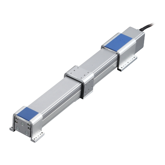
ROBO Cylinder RCP4W Actuator Slider
Dust-proof/Splash-proof Type
First Step Guide First Edition
Thank you for purchasing our product.
Make sure to read the Safety Guide and detailed Instruction Manual (DVD) included with the product in addition to
this First Step Guide to ensure correct use.
This Instruction Manual is original.
Warning : Operation of this equipment requires detailed installation and operation instructions which are
provided on the DVD Manual included in the box this device was packaged in. It should be retained
with this device at all times.
A hardcopy of the Manual can be requested by contacting your nearest IAI Sales Office listed at
the back cover of the Instruction Manual or on the First Step Guide.
• Using or copying all or part of this Instruction Manual without permission is prohibited.
• The company names, names of products and trademarks of each company shown in the sentences are registered
trademarks.
Product Check
The standard configuration of this product is comprised of the following parts
parts, contact your local IAI distributor.
1. Parts
No.
Part Name
Model
Refer to "How to read the model
1
Main Body
plate", "How to read the model No."
Accessories
2
Motor • Encoder Cable
(Note 1)
3
First Step Guide
4
Instruction Manual (DVD)
5
Safety Guide
Note 1
Please refer to [Wiring] for the applicable cables.
2. How to read the model plate
Model
MODEL
RCP4W-SA5C-I-35P-10-500-P3-M-A1
Serial number
SERIAL No.000061911
MADE IN JAPAN
3. How to read the model No.
R C P 4 W - S A 5 C - I - 3 5 P - 1 0 - 5 0 0 - P 3 - M - A 1 - * *
Series
<Type>
SA5C, SA6C
SA7C
<Encoder Type>
I : Incremental
<Motor Type>
35P : 35 □
42P : 42 □
56P : 56 □
<Lead>
5 : 5mm
6 : 6mm
8 : 8mm
10 : 10mm
12 : 12mm
16 : 16mm
Note 1
Identification for IAI use only : It may be displayed for IAI use. It is not a code to show the model
type.
1. Handling of Robot
Pay attention to the followings when carrying an actuator by itself.
(1) Handling of the Packed Product
•
Do not damage or drop. The package is not applied with any special treatment that enables it to resist an
impact caused by a drop or crash.
•
An operator should never attempt to carry a heavy package on their own. Also, use an appropriate way for
transportation.
•
If the shipping box is to be left standing, it should be in a horizontal position. Follow the instruction if there is
any for the packaging condition.
•
Do not step or sit on the package.
•
Do not put any load that may cause a deformation or breakage of the package.
(2) Handling after Unpackaged
•
Do not carry the actuator by holding the cable, or do not move it by pulling the cable.
•
Hold the body base when transporting the actuator.
•
Do not hit or drop the product while carrying.
•
Do not give any excessive force to any of the sections in the actuator.
2. Handling of Multi-Axes Type
This is the case that this product is delivered with other actuators being combined. Multi-axes type will be
delivered in a package with an outer case fixed to a wooden base. Tables are fixed so they would not accidently
move while in transportation. The end of the actuator is also fixed to avoid it swinging by external vibration.
(1) Handling of the Packed Product
•
Do not damage or drop. The package is not applied with any special treatment that enables it to resist an
impact caused by a drop or crash.
•
An operator should never attempt to carry a heavy package on their own. Also, use an appropriate way for
.
If you find any fault or missing
transportation.
•
When suspending the package using ropes, pass the ropes from underneath the reinforcement frames at
the bottom of the base. When lifting with a forklift, also place the forks underneath the base.
•
Do not apply an impact on the package or let it bounce when putting it down.
•
Do not step or sit on the package.
Quantity
Remarks
•
Do not put any load that may cause a deformation or breakage of the package.
1
(2) Handling after Unpackaged
•
Secure the tables to prevent sudden movement during transport.
•
Appropriately fix the tip of the actuators if it is overhanging so it would not widely shake with external
1
vibration. If the actuator assembly is transported without the ends being secured, do not apply an impact of
1
0.3G or more.
1
•
In the case that the actuator needs to be carried up with ropes or another method, be sure to use an
1
appropriate cushioning to avoid the robot being deformed or put on an excessive pressure. And also, be
sure to keep the robot in a stable and horizontal posture. Make a tool to utilize the attachment holes and
tapped holes on the actuator and attach it if necessary.
•
Do not attempt to apply load to the actuator or connector box. Also, avoid the cables being pinched or
caused an excessive deformation.
3. Handling of Robot Mounted on Mechanical Equipment (System)
Followings are the cautions for when transporting the actuators installed in the machinery equipment (system) in
the whole system.
•
Affix the table so they would not move while transporting.
•
If any end of the actuator is overhanging, secure it properly to avoid significant movement due to external
vibration. If the actuator assembly is transported without the ends being secured, do not apply an impact of
0.3G or more.
•
Do not attempt to apply load to actuators or connector box when hanging the machinery equipment
(system) with tools such as a rope. Also, avoid the cables being pinched or caused an excessive
deformation.
Installation and Storage • Preservation Environment
Note 1
Identification for IAI use only
1. Installation Environment
<Option>
Do not use this product in the following environment.
A1
: Cable exit to the left side
Also make sure to keep enough work space necessary for maintenance.
A3
: Cable exit to the right side
•
Location exposed to radiant heat from a huge heat source such as the heat treatment
GE : Food grease indicated
•
Location where the surrounding air temperature exceeds the range of 0 to 40 °C
NM : Reversed home specification
•
Location where condensation occurs due to abrupt temperature changes
TFL : Wall mount to the left type
•
Location where relative humidity exceeds 85%RH
TFR : Wall mount to the right type
•
HFL : Ceiling mount to the left type
The product gains the water-proof performance of IP65 protection structure if an air purge is conducted.
•
Location exposed to direct sunlight
HFR : Ceiling mount to the right type
•
Location exposed to corrosive gases or combustible gases
•
<Cable Length>
Location exposed to significant amount of dust, salt or iron powder (Outside of ordinary assembly plant)
N
: No cable
•
Location where oil (includes oil mist and cutting fluid) or chemical is splashed
P
: 1m
•
Location where the product main body receives vibration or hit impact
S
: 3m
When using the product in any of the locations specified below, provide a sufficient shield.
M
: 5m
•
Place subject to electrostatic noise
X□□ : Specified length
•
Location where exposed to the influence of strong electric or magnetic field
R□□ : Robot Cable
•
Location where exposed to the influence of ultraviolet or radiant rays
<Applicable Controller>
2. Storage • Preservation Environment
P3 : PCON-CA
The storage and preservation environment should comply with the same standards as those for the installation
environment. In particular, when the machine is to be stored for a long time, pay close attention to environmental
<Stroke>
conditions so that no dew condensation forms.
Unless specially specified, moisture absorbency protection is not included in the package when the machine is
delivered. In the case that the machine is to be stored and preserved in an environment where dew condensation
is anticipated, take the condensation preventive measures from outside of the entire package, or directly after
opening the package.
For storage and preservation temperature, the machine withstands temperatures up to 60 °C for a short time, but
in the case of the storage and preservation period of 1 month or more, control the temperature to 50 °C or less.
Storage and preservation should be performed in the horizontal condition. In the case it is stored in the packaged
condition, follow the posture instruction if any displayed on the package.
Caution in Handling
Names of the Parts
1. Standard Type
Bracket (Front)
Base
Table
Bracket (Rear)
Bolt Cover (Front)
Bolt Cover (Rear)
Grommet
Side Cover
Front Cover
Opening (with seal)
Please refer to the Catalog or the Instruction Manual (DVD) for the dimensions and profile.
2. Wall-hang Type
Bolt Cover (Front)
Bolt Cover (Rear)
Bracket (Front)
Bracket (Rear)
Opening (with seal)
Please refer to the Catalog or the Instruction Manual (DVD) for the dimensions and profile.
3. Ceiling Type
Bolt Cover (Front)
Bracket (Rear)
Bracket (Front)
Opening (with seal)
Please refer to the Catalog or the Instruction Manual (DVD) for the dimensions and profile.
Motor Cover
Right
Left
Cable
Air Inlet
φ6 for Air Purge
Right
Left
Bolt Cover (Rear)
Right
Left
Advertisement
Table of Contents

Related Manuals for IAI RCP4W


Summary of Contents for IAI RCP4W
- Page 1 Note 1 Identification for IAI use only : It may be displayed for IAI use. It is not a code to show the model is anticipated, take the condensation preventive measures from outside of the entire package, or directly after type.
- Page 2 Dedicated connection cable frequently. (connects controller and RCP4W) • Separate the I/O line, communication line and power line from each other. Ober der Röth 4, D-65824 Schwalbach am Taunus, Germany Do not store in the same duct.
Need help?
Do you have a question about the RCP4W and is the answer not in the manual?
Questions and answers