
Related Manuals for RKI Instruments 03 Series


Summary of Contents for RKI Instruments 03 Series
- Page 1 03 Series Operator’s Manual Part Number: 71-0304 Revision: P3 Released: 11/4/14 www.rkiinstruments.com...
- Page 2 Typical calibration frequencies for most applications are between 1 and 3 months, but can be required more often or less often based on your usage. 03 Series Operator’s Manual...
- Page 3 Warranty RKI Instruments, Inc. warrants the 03 Series Single Gas Monitor sold by us to be free from defects in materials, workmanship, and performance for a period of two (2) years from the date of shipment from RKI Instruments, Inc. This includes the instrument and the original sensor. Replacement parts are warranted for one (1) year from the date of their shipment from RKI Instruments, Inc.
-
Page 4: Table Of Contents
Turning Off the 03 Series ........ - Page 5 Parts List............70 WARNING: Understand this manual before operating the 03 Series.
-
Page 6: Introduction
The 03 Series is even small enough to be placed conveniently in a pocket. The 03 Series offers the following features: •... -
Page 7: Specifications
Specifications Table 1: 03 Series Specifications CO-03 HS-03 OX-03 Target Gas Carbon Monoxide Hydrogen Sulfide Oxygen (CO) Detection Range 0 to 500 ppm 0 to 100.0 ppm 0 to 40.0% vol. Display Increment 1 ppm 0.5 ppm 0.1% vol. Detection... - Page 8 • Belt clip • Wrist strap • IrDA/USB cable for downloading data to computer • Product CD, includes 03 Series Datalogging Program and 03 Series User Setup Program Dimensions and 2.2” (54mm) W x 2.6” (67mm) H x 0.9” (24mm) D;...
-
Page 9: Description
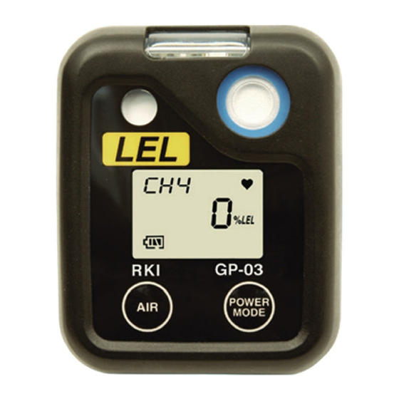
Figure 1: Components of the 03 Series Case The 03 Series’ sturdy, high-impact plastic case is blue and consists of a front and rear case. The case is suitable for use in many environmental conditions, indoors and out. The unit is dust proof and weather resistant. -
Page 10: Sensor Gasket, Sensor Membrane, And Charcoal Filter
The sensor membrane allows ambient air to diffuse past it to the sensor. The three sensors used in the three 03 Series models use different detection principles as described below. -
Page 11: Control Buttons
Calibration Mode or Setup Mode. Alarm LED The 03 Series has one red alarm LED. It alerts you to gas, low battery, and sensor failure alarms. The alarm LED is located at the top of the front case beneath a clear plastic lens. -
Page 12: Irda Port
IrDA protocol. A computer’s infrared port or an IrDA/USB cable connected to a computer’s USB port can be used to download data saved by the 03 Series to a computer using the 03 Series Data Logger Management Program. See the 03 Series Data Logger Management Program operator’s manual for data logging and... -
Page 13: Protective Rubber Boot
(standard) and the belt clip (optional). The alligator clip is shown in Figure 3 below. The alligator clip can be used to attach the 03 Series to clothing or a belt. Teeth in the clip’s jaws prevent the unit from slipping off. The clip can be rotated in 45 degree turns if necessary. - Page 14 The belt clip is shown in Figure 4 below and is used to easily clip the 03 Series on a belt. Belt Clip Figure 4: Belt Clip 9 • Description 03 Series Operator’s Manual...
-
Page 15: Start Up
Start Up This section explains how to start up the 03 Series and to get it ready for operation. NOTE: The screens shown in this section are for a CO-03. If you are using a different version of the 03 Series, your instrument screen will vary slightly from those shown below. - Page 16 To perform a calibration, press and release the POWER MODE button. Depending on the value entered into the One Touch Cal Time parameter using the 03 Series User Setup Program, the instrument will display either the A--CAL menu item or the E--CAL menu item in Calibration Mode.
- Page 17 The alarm LED and buzzer will pulse several times. Press and release the POWER MODE button. Depending on the value entered into the One Touch Cal Time parameter using the 03 Series User Setup Program, the instrument will display either the A--CAL menu item or the E--CAL menu item in Calibration Mode.
- Page 18 6. If Bump Test Limit Display is set to Off (factory setting), proceed to Step 8. 7. If Bump Test Limit Display is set to On using the 03 Series User Setup Program, the next screen will depend on how Bump Test Limit Check is set in Setup Mode or using the 03 Series User Setup Program.
- Page 19 If you do not perform a successful bump test, the buzzer will continue to beep and the LED will continue to flash for 6 seconds every 5 seconds and the unit will not enter normal operation. 03 Series Operator’s Manual Start Up • 14...
- Page 20 NEXT 8. The Date/Time Screen appears for a few seconds. 2014 1.31 8:20 This screen displays the current date and time. 9. The Battery Voltage Screen appears for a few seconds. bAtt 15 • Start Up 03 Series Operator’s Manual...
- Page 21 • STEL alarm setpoint (CO and H2S only) • TWA alarm setpoint (CO and H2S only) 11. If the 03 Series experiences a sensor failure during start up, the following screen will appear. SENSOR FAIL The instrument cannot be used if a sensor failure occurs. Replace the failed sensor.
-
Page 22: Performing A Fresh Air Adjustment
13. The 03 Series is now operating in Measuring Mode and monitoring for gas. The Normal Operation Screen appears and the instrument beeps once. -
Page 23: Turning Off The 03 Series
2. Release the button when the LCD is blank. The unit is off. NOTE: If Power Off Password Protection is turned On (factory setting is Off ) using the 03 Series User Setup Program, a password is required to turn the 03 Series off. When the password screen appears, adjust each digit with the AIR button and press and release the POWER MODE button to move on to the next digit. -
Page 24: Operation
On the OX-03, oxygen is displayed as volume percent. Adjusting the Buzzer Volume The buzzer volume on the 03 Series can be adjusted while in Measuring Mode if Buzzer Volume Selection is set to On (factory setting is Off ). The Buzzer Volume Selection setting can be adjusted using the 03 Series User Setup Program. -
Page 25: Display Mode, Co-03 And Hs-03
TWA values are cleared when the unit is turned off. To enter Display Mode, do the following: 1. Make sure the 03 Series is in the Measuring Mode Normal Operation screen. The 03 Series must be in the Normal Operation Screen for you to access Display Mode. - Page 26 The backlight will turn on and the PEAK Screen will appear. PEAK The peak reading since the 03 Series was turned on is displayed. 3. If you do not want to clear the peak reading, continue to the next step.
-
Page 27: Display Mode, Ox-03
“L” or an “A” will appear under the full scale value to indicate whether the alarms are set to latching (L) or auto-resetting (A). This setting can be adjusted using the 03 Series User Setup Program. F. S. 7. Press and release the POWER MODE button again to proceed to the Date/Time Screen. - Page 28 To enter Display Mode and view items or reset the peak readings, do the following: 1. Make sure the 03 Series is in the Measuring Mode Normal Operation screen. The 03 Series must be in the Normal Operation Screen for you to access Display Mode.
- Page 29 Full Scale Screen. The detection range full scale value is displayed. An “L” or an “A” will appear under the full scale value to indicate whether the alarms are set to latching (L) or auto-resetting (A). This setting can be adjusted using the 03 Series User Setup Program. F. S. 40.0 03 Series Operator’s Manual...
-
Page 30: Alarms
Alarm Indications The 03 Series will sound the buzzer, flash its alarm LED, and vibrate when the target gas concentration rises above (falls below for oxygen) the warning level. The 03 Series also sounds the buzzer, flashes its alarm LED, and vibrates when the alarm level is reached. - Page 31 03 Series. (Or there • Back light turns on. • Vibrator pulses at could be a problem • ALRM appears same rate as alarm with the unit.)
- Page 32 1. Follow your established procedure for an increasing gas condition or a decreasing oxygen condition. 2. If your unit is set for latching alarms, reset the alarm using the POWER MODE button once the alarm condition has been cleared. 27 • Operation 03 Series Operator’s Manual...
- Page 33 2. Reset the alarm by pressing and releasing the POWER MODE button after the alarm condition has cleared. 3. Calibrate the 03 Series as described in “Calibration Mode” on page 31. 4. If the over range condition continues, replace the sensor as described in “Replacing the Sensor”...
- Page 34 2. Attempt to change the date using the DATE menu item in Calibration Mode. See “Setting the Date and Time” on page 33. 3. If the date cannot be set correctly, contact RKI Instruments, Inc. as soon as possible. 29 • Operation...
-
Page 35: Data Logging
Data Logging The 03 Series features the ability to log data to its internal memory and download it to a computer via the IrDA port on the top of the case. It logs normal operation gas readings, alarm data, calibration data, and bump test data. -
Page 36: Calibration Mode
Calibration Mode. Although it will respond to gas in parts of AIR CAL, A--CAL., M--CAL., and BUMP, there are no gas alarm indications. 1. Take the 03 Series to a non-hazardous area and turn it off if it is on. 31 • Calibration Mode 03 Series Operator’s Manual... - Page 37 START 7. At the START screen, press and release the POWER MODE button. The 03 Series will begin its start-up sequence. The Calibration Mode menu items are described below in the order in which they appear while moving through Calibration Mode.
-
Page 38: Setting The Date And Time
Calibration Mode is the same as a fresh air adjustment in Normal Mode. The AIR menu item is available in Calibration Mode for convenience when performing a complete calibration. WARNING: Calibrate the 03 Series in a non-hazardous environment. 33 • Calibration Mode 03 Series Operator’s Manual... -
Page 39: Performing An Automatic Span Adjustment (Zero Adjustment For Ox-03) In A--Cal
The A--CAL menu item only appears in Calibration Mode if the One Touch Cal Time parameter in the 03 Series User Setup Program is set to 0 (factory setting). If One Touch Cal Time is set to anything other than 0, E-- CAL will replace A--CAL. - Page 40 Performing a span adjustment (zero adjustment for OX-03) requires the use of a calibration kit. A calibration kit is available from RKI Instruments, Inc. for each 03 Series model (see “Parts List” on page 70). You will need: •...
- Page 41 2. At the A--CAL screen, press and release the POWER MODE button. A screen appears that displays the calibration gas concentration that the 03 Series expects you to use. A--CAL. If the displayed concentration matches the calibration cylinder concentration, continue with Step 4.
- Page 42 Calibration Tubing Calibration Adapter Figure 5: Calibration Kit Assembly 5. Confirm that the regulator on/off knob is turned all the way clockwise (closed) and screw the calibration gas cylinder onto the regulator. 37 • Calibration Mode 03 Series Operator’s Manual...
- Page 43 6. Push the calibration adapter onto the 03 Series’ sensor face as shown in Figure 6. The calibration adapter secures itself to the instrument by latching on to two recesses in the instrument’s rear case. The rubber boot (if installed) does not need to be removed to install the adapter.
-
Page 44: Performing An Easy Span Adjustment (Zero Adjustment For Ox-03) In E--Cal
The E--CAL menu item only appears in Calibration Mode if the One Touch Cal Time parameter in the 03 Series User Setup Program is set to anything other than 0 (factory setting). When One Touch Cal Time is set to 0, A-- CAL will replace E--CAL. - Page 45 Performing a span adjustment (zero adjustment for OX-03) requires the use of a calibration kit. A calibration kit is available from RKI Instruments, Inc. for each 03 Series model (see “Parts List” on page 70). You will need: •...
- Page 46 2. At the E--CAL screen, press and release the POWER MODE button. A screen appears that displays the calibration gas concentration that the 03 Series expects you to use. E--CAL. If the displayed concentration matches the calibration cylinder concentration, continue with Step 3.
- Page 47 Calibration Tubing Calibration Adapter Figure 7: Calibration Kit Assembly 5. Confirm that the regulator on/off knob is turned all the way clockwise (closed) and screw the calibration gas cylinder onto the regulator. 03 Series Operator’s Manual Calibration Mode • 42...
- Page 48 Step 12. See “Troubleshooting” on page 63 to investigate the cause of the issue. 9. At the end of the countdown, the 03 Series will attempt to make a span 43 • Calibration Mode 03 Series Operator’s Manual...
- Page 49 PASS If the Maximum Span setting is turned On (factory setting is Off ) using the 03 Series User Setup Program, the LCD will show the maximum reading the sensor could have been calibrated to before returning to the E--CAL screen.
-
Page 50: Performing A Manual Span Adjustment (Zero Adjustment For Ox-03) In M--Cal
Performing a span adjustment (zero adjustment for OX-03) requires the use of a calibration kit. A calibration kit is available from RKI Instruments, Inc. for each 03 Series model (see “Parts List” on page 70). The procedure below describes a span adjustment (zero adjustment for OX-03). - Page 51 3. Use the sample tubing to connect the calibration adapter to the regulator. Attach the tubing to the calibration adapter on the inlet side as shown below in Figure 9. To Fixed Flow Regulator Calibration Tubing Calibration Adapter Figure 9: Calibration Kit Assembly 03 Series Operator’s Manual Calibration Mode • 46...
- Page 52 4. Confirm that the regulator on/off knob is turned all the way clockwise (closed) and screw the calibration gas cylinder onto the regulator. 5. Push the calibration adapter onto the 03 Series’ sensor face as shown in Figure 10. The calibration adapter secures itself to the instrument by latching on to two recesses in the instrument’s rear case.
-
Page 53: Performing A Bump Test In Bump
Performing a Bump Test in BUMP NOTE: Bump Test Function must be set to On using the 03 Series User Setup Program in order for BUMP to appear in Calibration Mode. If Bump Test Function is set to Off , BUMP will not appear. See the 03 Series User Setup Program Operator’s Manual for... - Page 54 BUMP If the value is not correct, you can change it by changing the A--CAL gas value in Calibration Mode or Setup Mode or by using the 03 Series Data Logger Management Program or the 03 Series User Setup Program.
- Page 55 4. Confirm that the regulator on/off knob is turned all the way clockwise (closed) and screw the calibration gas cylinder onto the regulator. 5. Push the calibration adapter onto the 03 Series’ sensor face as shown in Figure 12. The calibration adapter secures itself to the instrument by latching on to two recesses in the instrument’s rear case.
- Page 56 03 Series User Setup Program Operator’s Manual for a complete description of this parameter. 9. When Calibration After Bump Test Failed is set to Off : • The instrument will display a “P” for pass or an “F” for fail.
- Page 57 Bump Test Time(sec) and Calibration Time(sec) After Bump Test Failed parameters’ values. These parameters can be changed using the 03 Series User Setup Program. The countdown time for the calibration is the Calibration Time(sec) After Bump Test Failed value (factory setting is 90 seconds) minus the Bump Test Time(sec) value (factory setting is 30 seconds).
- Page 58 12. Remove the regulator from the calibration gas cylinder. 13. Leave the regulator connected to the calibration adapter for convenience. 14. Store the components of the calibration kit in a safe and convenient place. 53 • Calibration Mode 03 Series Operator’s Manual...
-
Page 59: Viewing The Instrument's Firmware Version
(30010 in this example) and the bottom line is the firmware checksum (C1AC in this example). 30010 C1AC 3. Press and release the POWER MODE button to return to the ROM screen. 03 Series Operator’s Manual Calibration Mode • 54... -
Page 60: Setup Mode
AIR CAL, A--CAL, and M--CAL, there are no gas alarm indications. 1. Take the 03 Series to a non-hazardous area and turn it off if it is on. 2. Press and hold the AIR button, then press and hold the POWER MODE button. - Page 61 Setup Mode or turn on the unit and proceed to Measuring Mode. NOTE: If you have forgotten your password, contact RKI Instruments, Inc. 5. If the PASS--W menu item is set to OFF , the DATE Screen is displayed.
-
Page 62: Setting The Date And Time In Date
START 10. At the START screen, press and release the POWER MODE button. The 03 Series will begin its start-up sequence. The Setup Mode menu items are described below in the order in which they appear while moving through Setup Mode. -
Page 63: Performing A Manual Span Adjustment (Zero Adjustment For Ox-03) In M--Cal
Setting the Alarm Points Entering the ALM--P menu item allows you to set the alarm points. ALM--P Table 5 below lists the factory set alarm points for each type of 03 Series. Table 5: Factory Set Alarm Points Channel Warning... - Page 64 A screen with the TWA setpoint flashing is displayed. 9. Use the AIR button to adjust the TWA setpoint to the desired value. 10. Press and release the POWER MODE button to save the new TWA setpoint. 59 • Setup Mode 03 Series Operator’s Manual...
-
Page 65: Adjusting The Bump Test Limit Check Setting
BP--CHK. menu item. This menu item will always appear in Setup Mode even if Bump Test Function and/or Bump Limit Display are set to Off in the 03 Series User Setup Program. BP--CHK. 1. At the BP--CHK. screen, press and release the POWER MODE button. -
Page 66: Setting The Password
3. If the password feature was set to OFF , the unit will exit the PASS--W menu item and return to the PASS--W screen. PASS--W With the password feature set to OFF , you will be able to enter Setup 61 • Setup Mode 03 Series Operator’s Manual... - Page 67 8. Repeat Step 5 through Step 7 until you have set all four of the digits. 9. When you save the last digit, the unit will return to the PASSWORD screen. PASS--W 03 Series Operator’s Manual Setup Mode • 62...
-
Page 68: Maintenance
Maintenance This section describes troubleshooting procedures for the 03 Series. It also describes how to change the 03 Series’ batteries, replace the sensor, replace the sensor membrane, and replace the charcoal filter (CO-03 only). WARNING: RKI Instruments, Inc. recommends that service, calibration, and repair of RKI instruments be performed by personnel properly trained for this work. -
Page 69: Replacing The Batteries
Table 7: Troubleshooting the 03 Series Symptoms Probable Causes Recommended Action “FAIL” displays • The calibration 1. Check all calibration tubing value may not for leaks or for any bad during span match the cylinder connections. adjustment. gas concentration. 2. Make sure the 03 Series •... - Page 70 To Replace the Batteries 1. Verify that the 03 Series is off. 2. Release the left side of the alligator clip or belt clip (if installed). Figure 13: Clip Release 3. Rotate the captive battery cover screw counterclockwise to remove the battery cover.
-
Page 71: Replacing The Sensor
NOTE: An alligator or belt clip may be installed on the instrument but is not shown in the figures in this section. 1. Verify that the 03 Series is off. 2. Remove the rubber boot, if installed. 3. With a small Phillips screwdriver, carefully unscrew the four screws that attach the rear case to the front case. - Page 72 The CO and H S sensors have alignment slots which match up with alignment tabs in the sockets. Forcing a sensor into its socket may damage the sensor or the socket. 67 • Maintenance 03 Series Operator’s Manual...
-
Page 73: Replacing The Sensor Membrane And Charcoal Filter
HS-03 and OX-03 only have a sensor membrane. The CO-03 has a sensor membrane and a charcoal filter. 1. Verify that the 03 Series is off. 2. Remove the rubber boot, if installed. 3. With a small Phillips screwdriver, carefully unscrew the four screws that attach the rear case to the front case. - Page 74 10. Turn the front case right side up and carefully secure it to the rear case using the screws you removed in Step 3. 11. Reinstall the rubber boot if it is being used. 69 • Maintenance 03 Series Operator’s Manual...
-
Page 75: Parts List
Parts List Table 6 lists replacement parts and accessories for the 03 Series. Table 8: Parts List Part Number Description 06-1248RK Calibration kit tubing (specify length in feet) 07-6031 Gasket for battery cover 07-6032 Gasket between front and rear case... - Page 76 Regulator, fixed flow, 0.5 LPM, with gauge and knob, for 58/34 liter aluminum cylinder, 103 liter steel cylinder 81-1146 Calibration adapter for 03 Series 81-CO03 Calibration kit for CO-03 containing: one 103-liter steel gas cylinder (50 ppm CO in air), regulator,...
Need help?
Do you have a question about the 03 Series and is the answer not in the manual?
Questions and answers