Table of Contents
Advertisement
Quick Links
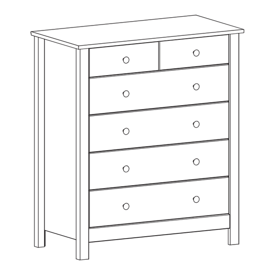
Osaka 4+2 Drawer Chest
Assembly Instructions -
Dimensions
:
Width
80.1 cm
Depth
:
40.0 cm
:
91.6 cm
Height
Assembly Instructions -
If you need help or have damaged or missing parts, call the Argos Customer Helpline: 0845 640 30 30
350262
Please keep for future reference
Please keep for future reference
White 2377889
Black 2278342
Issue 1 - 15-05-2014
Advertisement
Table of Contents

Related Manuals for Argos Osaka 2377889


Summary of Contents for Argos Osaka 2377889
- Page 1 80.1 cm Depth 40.0 cm 91.6 cm Height Assembly Instructions - Please keep for future reference If you need help or have damaged or missing parts, call the Argos Customer Helpline: 0845 640 30 30 Issue 1 - 15-05-2014 350262...
- Page 2 ! Safety and Care Advice Important - Please read these instructions fully before starting assembly • Check you have all the • Do not stand or put weight on components and tools listed on the product, this could cause pages 2 and 3. damage.
- Page 3 Components - Panels If you have damaged or missing components, call the Argos Customer Helpline: 0845 640 30 30 Please check you have all the panels listed below (80,1 cm x 40 cm) Back rail (68,3 cm x 7 cm)
- Page 4 Components - Fittings Please check you have all the panels listed below Note: The quantities below are the correct amount to complete the assembly. In some cases more fittings may be supplied than are required. ø7.8 x 40mm Wooden dowel x ø6 x 30mm Wooden dowel x 24 ø3 x 35mm Screw x ø15 x 10.5mm Cam x 18...
-
Page 5: Ø7.8 X 40Mm Wooden Dowel X
Assembly Instructions Step 1 Assembly of the chest. Step 1.1 Fix the posts onto the ø4 x 25mm Screw x sides using screws into the holes indicated. The top of the posts the sides must be flush. Step 1.2 Knock the dowels ø7.8 x 40mm Wooden dowel x ø5 x 8, cc34mm Bolt x 2 into the holes indicated... -
Page 6: Ø5.8 X 19Mm Screw X
Assembly Instructions Step 1.3 Slide the top of the ø5.8 x 8mm Screw x 16 ø5.8 x 19mm Screw x drawer runners backwards. You can identify the front end of the drawer runner ø18 x 9mm Spacer x 245 x 17 x 10mm Drawer runner x the two M4 holes. - Page 7 Assembly Instructions Step 1.4 Slide the top of the draw- ø5.8 x 8mm Screw x 8 ø5.8 x 19mm Screw x er runners forwards. Place the Spacers shown, and fix the back ø18 x 9mm Spacer x end of the upper drawer runners to the sides using screws...
-
Page 8: Ø3.5 X 14Mm Screw X
Assembly Instructions Step 1.6 Fix the drawer runner ø3.5 x 14mm Screw x Support for drawer runner x 2 supports to the top using screws into the holes indicated. Step 1.7 ø5.8 x 8mm Screw x 2 245 x 17 x 10mm Drawer runner x Slide the top of the drawer runners... -
Page 9: Ø4,2 X 9,5Mm Screw X
Assembly Instructions Step 1.9 Knock the dowels into ø7.8 x 40mm Wooden dowel x the holes indicated on the back rail using a small hammer. Step 1.10 Fix the angles using ø4,2 x 9,5mm Screw x 44 x 23 x 23mm Angle x screws into the holes... - Page 10 Assembly Instructions Step 1.12 Place the top onto the ø15 x 10.5mm Cam x 4 sides Push cams into the holes indicated on the sides Arrows pointing towards the top Turn the cams to the right to fix the top Step 1.13 Place the front rail ø4,2 x 9,5mm Screw x...
-
Page 11: Step
Assembly Instructions Step 1.14 Distribute equally ! Distribute equally ! Place the backs into 1.2 x 15mm Nail x the rabbet on the top into the H-profile onto the posts Important! Make sure the angle between the and the posts 90°... -
Page 12: Hammer
Assembly Instructions Step 2 Assembly of the drawers. Step 2.1 Fix the drawer sides ø3 x 35mm Screw x to the drawer backs as shown, using screws Step 2.2 Knock the dowels ø6 x 30mm Wooden dowel x 24 into the holes indicated on the drawer sides using a smal hammer. - Page 13 Assembly Instructions Step 2.4 Screw the bolts into ø5 x 8, cc34mm Bolt x 12 the holes indicated on the drawer fronts Step 2.5 Push the drawer fronts ø15 x 10.5mm Cam x 12 onto the drawer sides Place cams into the holes indicated.
- Page 14 Assembly Instructions Step 2.7 Fix the metal knobs ø27 x 24mm Metal Knob x M4 x 20mm Screw x the drawer fronts using screws Step 2.8 Pull out the drawer M4 x 9mm Screw x runners. Slide the drawers onto the runners. Fit and fix the lower drawer first and work your way up.
Need help?
Do you have a question about the Osaka 2377889 and is the answer not in the manual?
Questions and answers