Table of Contents
Advertisement
Quick Links
Download this manual
See also:
Instruction Manual
QQ
3 7 63 1515 0
SERVICE MANUAL
TE
L 13942296513
www
.
http://www.xiaoyu163.com
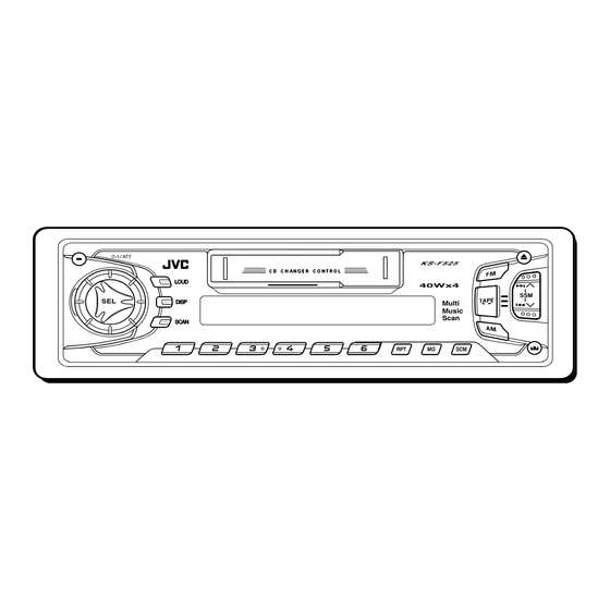
CASSETTE RECEIVER
KS-F525
LOUD
LOUD
DISP
DISP
SCAN
SCAN
Contents
Safety precaution
Disassembly method
Adjustment method
Description of major ICs
x
ao
u163
y
i
COPYRIGHT
2002 VICTOR COMPANY OF JAPAN, LTD.
http://www.xiaoyu163.com
2 9
8
Multi
Music
Scan
Q Q
3
6 7
1 3
1 5
1- 2
1- 3
1-12
1-15~20
co
.
9 4
2 8
0 5
8
2 9
9 4
2 8
Area Suffix
EE ----- Russian Federation
m
KS-F525
9 9
9 9
No.49708
Feb. 2002
Advertisement
Table of Contents

Related Manuals for JVC KS-F525


Summary of Contents for JVC KS-F525
- Page 1 KS-F525 3 7 63 1515 0 SERVICE MANUAL CASSETTE RECEIVER KS-F525 LOUD LOUD DISP DISP Multi Music Scan SCAN SCAN L 13942296513 Area Suffix EE ----- Russian Federation Contents Safety precaution 1- 2 Disassembly method 1- 3 Adjustment method...
-
Page 2: Safety Precaution
KS-F525 3 7 63 1515 0 Safety precaution Burrs formed during molding may be left over on some parts of the chassis. Therefore, pay attention to such burrs in the case of preforming repair of this system. L 13942296513 u163 http://www.xiaoyu163.com... -
Page 3: Disassembly Method
KS-F525 3 7 63 1515 0 Disassembly method <Main body> Removing the front panel assembly (See Fig.1) Press the eject button in the lower right part of the front panel. Remove the front panel assembly from the body. Front panel assembly Eject button Fig.1... -
Page 4: Removing The Bottom Cover
KS-F525 3 7 63 1515 0 Removing the heat sink (See Fig.4) Remove the three screws A on the left side of the body. Heat sink Fig.4 Joints b Removing the bottom cover (See Fig.5 and 6) Bottom cover... -
Page 5: Removing The Mainboard
KS-F525 3 7 63 1515 0 Removing the main board (See Fig.7 and 8) Prior to performing the following procedure, remove the front panel assembly, the front chassis assembly, the heat sink and the bottom cover. Remove the screw B, the two screws C and the two... - Page 6 KS-F525 3 7 63 1515 0 Removing the control switch board (See Fig.10 to 12) Prior to performing the following procedure, remove the front panel assembly. Remove the four screws G attaching the rear cover on the back of the front panel assembly.
- Page 7 KS-F525 3 7 63 1515 0 Cassette mechanism ass’y <Removal of the cassette mechanism> Removing the head amplifier board. Head relay (See Fig.1 and 2) board For the 6pin wire extending from connector CN402 on the head amplifier board, disconnect it from the head relay board.
- Page 8 KS-F525 3 7 63 1515 0 Head relay board Removing the head relay board (See Fig.4) Unsolder the soldering b on the head relay board. Remove the screw C attaching the head relay board. Remove the head relay board in the direction of the...
- Page 9 KS-F525 3 7 63 1515 0 Cassette holder and holder arm Joint h Shaft Joint h Shaft Removing the play head (See Fig.9) Prior to performing the following procedure, remove the head relay board and the sub chassis. Fig.8 Remove the two screws F attaching the play head Pinch roller ass’y...
-
Page 10: Removing The Flywheel
KS-F525 3 7 63 1515 0 Removing the flywheel Cassette mechanism ass’y Reel disc board (See Fig.10 and 12) Soldering j Prior to performing the following procedure, remove the head relay board, the load arm, the sub chassis, the cassette holder, the holder arm and the reel disc Tab k board. - Page 11 KS-F525 3 7 63 1515 0 Push aside the gear and reattach the reel disc Ass’y( ). Removing the reel disc ass’y( ) (See Fig.12 to 15) ATTENTION: Prior to performing the following procedure, remove the reel disc ( ).
-
Page 12: Adjustment Method
KS-F525 3 7 63 1515 0 Adjustment method Frequency Range Test Instruments reqired for adjustment 1.Digital osclloscope(100MHz) FM1/FM2 : 87.5 MHz to 108.0 MHz 2.Frequency Counter meter FM3 : 65 MHz to 74 Hz 3.Electric voltmeter AM : (MW) 522 kHz to 1620 kHz 4.Wow &... - Page 13 KS-F525 3 7 63 1515 0 Arrangment of adjusting Head amplifier board section (Reverse side) VR401:Rch VR402:Rch (Dolby NR Frequency response adj) (Dolby NR level adj) C418 C413 C419 R412 C416 C414 R416 C421 C422 R414 C412 VR401 Q401...
- Page 14 KS-F525 3 7 63 1515 0 Item Conditions Adjustment and Confirmation methods S.Values Adjust Head Head height adjustment Test tape: azimuth Adjust the azimuth directly. When you SCC-1659 adjustment adjust the height using a mirror tape, VT703(10kHz) remove the cassette housing from the mechanism chassis.
-
Page 15: Description Of Major Ics
KS-F525 3 7 63 1515 0 Description of major ICs UPD178018AGC594(IC701) : System controller micon 1.Terminal Layout 24 – 1 41 – 64 2.Description Symbol Function Symbol Function KEY0 Key input 0 DOLBY O Dolby NR output H:Dolby NR ON... - Page 16 KS-F525 3 7 63 1515 0 BA4905-V3 (IC961) : Regulator 1.Pin layout 2.Block diagram REGULATOR L 13942296513 RESET RESET COMP VDD 5.7V CD 8V AUDIO 9V CTRL ILM 10V 3.Pin function Pin no. Symbol Function RESET If VDD voltage becomes 4V or less.RESET output becomes low level.
- Page 17 KS-F525 3 7 63 1515 0 CXA2559Q(IC401):Playback equalizer amplifier with music sensor 1.Pin layout 2.Blockdiagram 24dB 100k 7k/12k 300k MS MODE BIAS MUTE TAPE EQ FWD/RVS MS ON/ 300k 7k/12k 100k 24dB 3.Pin function Pin No. Symbol Function PBTC1...
- Page 18 KS-F525 3 7 63 1515 0 HA13158A (IC941) : Power amp 1. Pin layout 2. Block diagram PVCC2 PVCC1 INVCC STBY INPUTBUFFER1 AMP1 INPUTBUFFER2 AMP2 INPUTBUFFER3 AMP3 L 13942296513 INPUTBUFFER4 AMP4 MUTE PROTECTOR (ASO SURGE, TSD) LB1641 (IC402) : DC motor driver 2.
- Page 19 KS-F525 3 7 63 1515 0 LC75823W (IC651) : LCD driver 1. Pin Layout & Symbol 64 63 62 61 60 59 58 57 56 55 54 53 52 51 50 49 17 18 19 20 21 22 23 24 25 26 27 28 29 30 31 32 2.
- Page 20 KS-F525 3 7 63 1515 0 TEA6320T-X (IC161) : E.volume 1.Pin layout 2.Block diagram VOLUME 2 MUTE 0 to 55 dB FUNCTION BALANCE OUTRR OUTLR ZERO CROSS FENDER REAR POWER DETECTOR OUTRF OUTLF SUPPLY VOLUME 1 BASS TREBLE +20 to -31 dB...
- Page 21 KS-F525 3 7 63 1515 0 < M E M O > L 13942296513 u163 1-21 http://www.xiaoyu163.com...
- Page 22 KS-F525 3 7 63 1515 0 L 13942296513 u163 VICTOR COMPANY OF JAPAN, LIMITED MOBILE ELECTRONICS DIVISION PERSONAL & MOBILE NETWORK BUSINESS UNIT. 10-1,1Chome,Ohwatari-machi,Maebashi-city,371-8543,Japan 200202 (No.49708) http://www.xiaoyu163.com...
- Page 23 http://www.xiaoyu163.com 3 7 6 3 1 5 1 5 0 MOTOR SWITCH MAIN TAPE END.STANDBY MOTOR HEAD CJ402 CJ403 TO SPEAKER MOTOR METAL CONNECTOR TO REAR LINE OUT TAPE IN MODE CP961 STANDBY J931 PHOTO IC401 REEL L/R F PB EQ L/R R CXA2559Q DOLBY...
- Page 24 KS-F525 3 7 63 1515 0 < M E M O > L 13942296513 u163 http://www.xiaoyu163.com...
-
Page 25: Standard Schematic Diagrams
KS-F525 Standard schematic diagrams 3 7 6 3 1 5 1 5 0 Receiver & System control section 1 3 9 4 2 2 9 6 5 1 3 Tuner signal Front signal Rear signal w w w Tape PB / Main signal u 1 6 3 Parts are safety assurance parts. - Page 26 KS-F525 KS-F525 Mecha control circuit section 3 7 6 3 1 5 1 5 0 Q403 2SB1322/RS/-T R401 Q402 DTC114EKA-X CJ403 QGF1219F1-10 0.015 C411 R418 22/16 C409 IC401 1 3 9 4 2 2 9 6 5 1 3...
- Page 27 KS-F525 3 7 6 3 1 5 1 5 0 LCD & key control LCD1 CP701 VMC0335-001 IC652 RPM6938-SV4 JS601 1 3 9 4 2 2 9 6 5 1 3 QSW0793-001 R658 D601 R631 R651 MA152WK-X 1.5k D655 C651 0.01...
-
Page 28: Printed Circuit Boards
KS-F525 KS-F525 3 7 6 3 1 5 1 5 0 Printed circuit boards Front board (Forward side) Main board IC652 R652 D602 S619 D601 C653 R607 S601 R637 R608 C671 R609 R658 S609 R611 R639 R631 R633 D603... -
Page 29: Parts List
KS-F525 3 7 63 1515 0 PARTS LIST [ KS-F525 ] * All printed circuit boards and its assemblies are not available as service parts. Area suffix EE --------- Russian Federation L 13942296513 - Contents - 3- 2 Exploded view of general assembly and parts list (Block No.M1) 3- 5 Cassette mechanism assembly and parts list (Block No.MP) -
Page 30: Exploded View Of General Assembly And Parts List
KS-F525 3 7 63 1515 0 Exploded view of general assembly and parts list Block No. L 13942296513 u163 http://www.xiaoyu163.com... - Page 31 KS-F525 3 7 63 1515 0 Parts list (General assembly) Block No. M1MM Item Description Parts number Parts name Q'ty Area --------------- CASSETTE MECHA 1 CDS-801 FSYH4036-050 SHEET FSKL2001-004 MECHA BRACKET L FSKL2002-002 MECHA BRACKET R QYSDST2606Z SCREW 1 PCB+MECHA...
- Page 32 KS-F525 3 7 63 1515 0 Parts list (General assembly) Block No. M1MM Item Description Parts number Parts name Q'ty Area VMA4652-001SS EARTH PLATE FSKL4018-00B IC BRACKET FSKL4023-001 REG BRACKET FSKL4014-002 HEAT SINK FSKM3012-012 REAR BRACKET QYSDST2606Z SCREW 1 ANT...
-
Page 33: Cassette Mechanism Assembly And Parts List
KS-F525 3 7 63 1515 0 Cassette mechanism assembly and parts list Block No. CDS-801 CFD-409 100 101 102 FG-84M FG-84M SW-902 FG-84M SW-902 CFD-409 CFD-409 CFD-409 SW-522B L 13942296513 FG-84M FG-84M SW-522B FG-84M FG-84M LEN-315Y2 LEN-315Y2 CFD-409 LEN-315Y2... - Page 34 KS-F525 3 7 63 1515 0 Parts list (Cassette mechanism) Block No. MPMM Item Description Parts number Parts name Q'ty Area X-0801-1003S MAIN CHASSIS AS X-0801-1002S SLIDE CHASSIS A X-0801-1008S SIDE BKT ASS'Y X-0801-1010S EJECT CAM LIMIT X-0801-1013S CASSETTE HANGER...
- Page 35 KS-F525 3 7 63 1515 0 Parts list (Cassette mechanism) Block No. MPMM Item Description Parts number Parts name Q'ty Area 1-0801-4008S REEL DRIVER SPG 1-0801-4009S LOAD ARM SPG 1-0801-4011S HOLDER STAB SPG 1-0801-5001S BELT 1-0801-5002S FELT 1 7.5*18.5*1.0...
- Page 36 KS-F525 3 7 63 1515 0 Grease point 1/2 SW-902 SW-522B FG-84M CFD-409 LEN-315Y2 FG-84M SW-902 SW-902 SW-902 FG-84M FG-84M SW-902 FG-84M SW-902 FG-84M L 13942296513 FG-84M EP56 u163 http://www.xiaoyu163.com...
- Page 37 KS-F525 3 7 63 1515 0 Grease point 2/2 L 13942296513 u163 http://www.xiaoyu163.com...
- Page 38 KS-F525 3 7 63 1515 0 Electrical parts list (Main board) Block No. 01 Item Parts number Parts name Remarks Area Item Parts number Parts name Remarks Area QERF1HM-104Z E CAPACITOR 0.1MF 20% 50V C 944 NCB21EK-104X C CAPACITOR...
- Page 39 KS-F525 3 7 63 1515 0 Electrical parts list (Main board) Block No. 01 Item Parts number Parts name Remarks Area Item Parts number Parts name Remarks Area Q 12 2SC2412K/R/-X TRANSISTOR R 252 NRSA02J-223X MG RESISTOR Q 131...
- Page 40 KS-F525 3 7 63 1515 0 Electrical parts list (Main board) Block No. 01 Item Parts number Parts name Remarks Area R 980 NRSA02J-183X MG RESISTOR R 981 NRS181J-102X MG RESISTOR R 982 NRS181J-103X MG RESISTOR R 983 NRS181J-103X...
- Page 41 KS-F525 3 7 63 1515 0 Electrical parts list (Front board) Block No. 02 Item Parts number Parts name Remarks Area Item Parts number Parts name Remarks Area C 651 NCB31HK-103X C CAPACITOR R 641 NRSA02J-821X MG RESISTOR C 652...
- Page 42 KS-F525 3 7 63 1515 0 Electrical parts list (Mecha control board) Block No. 03 Item Parts number Parts name Remarks Area C 401 NDC31HJ-101X C CAPACITOR C 402 NDC31HJ-101X C CAPACITOR C 403 NDC31HJ-101X C CAPACITOR C 404...
- Page 43 KS-F525 3 7 63 1515 0 < M E M O > L 13942296513 u163 3-15 http://www.xiaoyu163.com...
-
Page 44: Packing Materials And Accessories Parts List
KS-F525 3 7 63 1515 0 Packing materials and accessories parts list Block No. Block No. P1 A2~A4 L 13942296513 KIT:A5~A9 u163 3-16 http://www.xiaoyu163.com... - Page 45 KS-F525 3 7 63 1515 0 Parts list (Packing) Block No. M3MM Item Description Parts number Parts name Q'ty Area FSPG4002-001 POLY BAG 1 INST.BOOK QPA00801205 POLY BAG 1 KIT QPA01003003 POLY BAG 1 HARD CASE FSYH4036-068 SHEET QPC03004315P...
Need help?
Do you have a question about the KS-F525 and is the answer not in the manual?
Questions and answers