Advertisement
Quick Links
U
DESCRIPTIO
This demonstration board provides 3.3V/4A and 5V/4A
outputs using a low EMI, 2-phase, adjustable, dual switch-
ing regulator controller. This design is ideally suited for
notebook computer system power supply applications.
Operating the two high side MOSFETs 180° out of phase
significantly reduces peak input ripple current, thereby
reducing radiated and conducted EMI. External parts
count, cost and size are minimized in this design. Output
voltages can be externally set to as low as 0.8V. The
controllers have overcurrent latch-off, which can be exter-
nally defeated, as well as internal current foldback for
overload situations. The overcurrent latch-off on one
controller can be configured to shut off the other output.
A soft latch for overvoltage conditions is also provided. In
addition to the two high current outputs, on-chip 5V/50mA
W
U
PERFOR A CE SU
Input Voltage Range
Input Voltage Limited by External MOSFET Drive and Breakdown Requirements
Outputs
Output Voltage: Controller 1; Externally Adjustable; 0 to 3A, 4A Pk
Output Voltage: Controller 2; Externally Adjustable; 0 to 3A, 4A Pk
5V Linear Regulator
3.3V Linear Regulator
Typical Output Ripple at 10MHz BW; 300kHz; I
TYPICAL PERFOR A CE CHARACTERISTICS A D BOARD PHOTO
Efficiency vs Load
100
90
80
70
60
50
0.001
0.01
OUTPUT CURRENT (A)
W W
ARY
Operating Temperature Range: 0°C to 50°C (continued on Page 2)
W
U
5V OUTPUT
3.3V OUTPUT
V
= 15V
IN
0.1
1
10
DC236TP01
DEMO MANUAL DC236
DESIGN-READY SWITCHERS
2-Phase Constant-Frequency
Synchronous, Dual-Output
and 3.3V/25mA linear regulators are also included. In the
optional standby mode, these internal regulators are ca-
pable of powering external system wake-up circuitry when
both high current controllers are shut down. Two low
current modes of operation are available: Burst Mode
operation offers highest efficiency while Burst Disable
mode provides constant-frequency operation down to 1%
of maximum designed load. The frequency is externally
DC-controlled over a 130kHz to 300kHz range. The con-
troller can operate at up to 99% duty cycle for very low
dropout conditions. The demonstration board operates on
an input supply of from 5.2V to 30V. Refer to the LTC
data sheet for other possible configurations. Gerber files
for this circuit board are available. Call the LTC factory.
, LTC and LT are registered trademarks of Linear Technology Corporation.
Burst Mode is a trademark of Linear Technology Corporation.
= 1A; 3.3V and 5V Outputs; V
O
IN
U
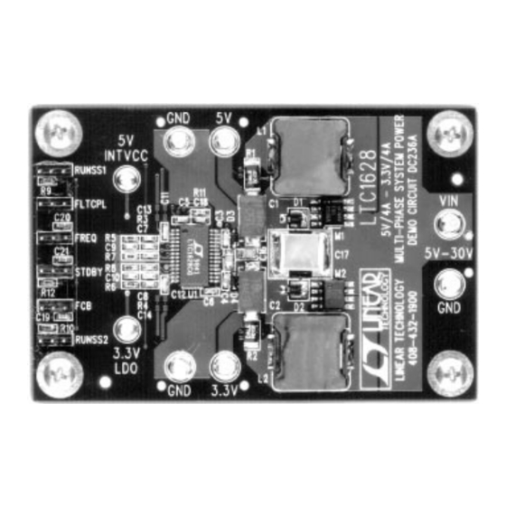
Demo Circuit 236A
LTC1628
DC/DC Converter
5.2V to 30V
5V ± 0.10V
3.33V ± 0.067V
5V ± 4%
3.3V ± 4%
= 15V
20mV
TM
®
1628
P-P
DC236 BP
1
Advertisement

Related Manuals for Linear Technology LTC1628


Summary of Contents for Linear Technology LTC1628
- Page 1 A soft latch for overvoltage conditions is also provided. In addition to the two high current outputs, on-chip 5V/50mA , LTC and LT are registered trademarks of Linear Technology Corporation. Burst Mode is a trademark of Linear Technology Corporation. PERFOR A CE SU Operating Temperature Range: 0°C to 50°C (continued on Page 2)
-
Page 2: Quick Start Guide
This demonstration board is easily set up to evaluate the 4. Connect the input power supply to the V and GND performance of the LTC1628. Please follow the proce- terminals on the right, center of the board. Do not dure outlined below for proper operation. - Page 3 SENSE2 3.3V 4A PK 1000pF SENSE2 RUN/SS2 C6,0.1µF C14,180pF SWITCHING FREQUENCY = 300kHz D3, D4 = CMDSH-3TR M1, M2 = FDS8936A DC236 F02 L1, L2 = PANASONIC N6 SERIES 10.1µH Figure 2. LTC1628 Fixed 5V/4A, 3.3V/4A, High Efficiency Dual Regulator...
-
Page 4: Parts List
44-1883-713-215 81-3-3983-0086 852-2-803-7380 65-221-8371 822-2-858-8773 (316) 992-7900 852-2-388-0629 65-280-0200 0342-43-2822 Kemet (864) 963-6300 44-1279-757-343 852-2-305-1168 65-484-2220 886-2-752-8585 Linear Technology (408) 432-1900 44-1276-677-676 81-3-3267-7891 852-2-803-7380 65-753-2692 886-2-521-7575 Midcom (605) 886-4385 Murata (800) 831-9172 Marcon (847) 696-2000 ON Semiconductor (602) 244-6600 81-3-3521-8315... - Page 5 Figure 3. Input Waveforms Comparing Single-Phase and 2-Phase Operation for Dual Switching Regulators Converting 12V to 5V and 3.3V at 3A Each. The Reduced Input Ripple with the LTC1628 2-Phase Regulator Allows Less Expensive Input Capacitors, Reduces Shielding Requirements for EMI and Improves Efficiency...
- Page 6 RMS input current and voltage. The LTC1628 is proof that these hurdles have been sur- Of course, the improvement afforded by 2-phase opera- mounted. The new device offers unique advantages for the tion is a function of the dual switching regulator’s relative...
- Page 7 DEMO MANUAL DC236 DESIGN-READY SWITCHERS OPERATIO Burst Mode operation allows the output MOSFETs to independently when FLTCPL is grounded. When the pin “sleep” between several PWM switching cycle periods of is tied to INTV the following operations result: normal MOSFET activity. The current loss due to charging 1.
- Page 8 DEMO MANUAL DC236 DESIGN-READY SWITCHERS OPERATIO Refer to the LTC1628 data sheet for further information on design include C9, C10, C13, C14, C18 and R11. Certain the internal operation and functionality descriptions of components may be larger than specific applications will the IC.
- Page 9 DEMO MANUAL DC236 DESIGN-READY SWITCHERS OPERATIO loads do not behave like the active load’s I-V characteris- secondary flyback winding. Keep these switch node- tics. Actual loads normally have V • C • f dependency related PC traces small and away from the “quiet” side of where C is internal chip capacitance and f is the frequency the IC (not just above and below each other on the opposite of operation.
- Page 10 DEMO MANUAL DC236 DESIGN-READY SWITCHERS OPERATIO The PGND-SGND tie point for the LTC1628 switching The traces that sense the voltage across the current- sensing resistor can be long but should run parallel to each regulator controllers is optimized by connecting the...
- Page 11 Information furnished by Linear Technology Corporation is believed to be accurate and reliable. However, no responsibility is assumed for its use. Linear Technology Corporation makes no represen- tation that the interconnection of its circuits as described herein will not infringe on existing patent rights.
- Page 12 4. PLATED HOLE WALL THICKNESS IS 1MIL MINIMUM 5. INTERNAL LAYERS ARE 1 OZ Cu dc236fa LT/TP 0200 1K REV A • PRINTED IN USA Linear Technology Corporation 1630 McCarthy Blvd., Milpitas, CA 95035-7417 (408) 432-1900 FAX: (408) 434-0507 www.linear-tech.com © LINEAR TECHNOLOGY CORPORATION 1998...
Need help?
Do you have a question about the LTC1628 and is the answer not in the manual?
Questions and answers