Advertisement
Quick Links
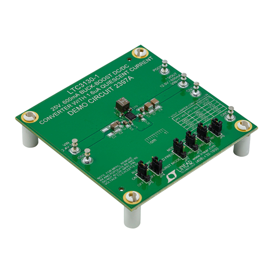
DESCRIPTION
Demonstration circuit 2397A features the
wide input voltage, wide output voltage operating range,
high efficiency, low noise monolithic DC/DC buck-boost
converter.
The LTC3130-1 has 4-pin selectable output voltages
and operates from input voltages of 2.4V to 25V. The
LTC3130-1 incorporates a proprietary low noise switching
algorithm which optimizes efficiency with input voltages
above, below, or equal to the output voltage and ensures
seamless transitions between operating modes.
The LTC3130-1's user selectable output voltages are 1.8V,
3.3V, 5.0V and 12V. To set the desired output voltage on
the DC2397A, use the "V
OUT
table on the front of the board to determine the jumper
settings for JP2 and JP3.
The DC2397A demo board has two user selectable oper-
ating modes: Burst Mode
PWM (JP1). In PWM Mode, the LTC3130-1 operates at
1.2MHz to allow high efficiency while minimizing the
solution footprint.
Internal compensation reduces footprint size by reducing
the number of external components. This also simplifies
the design process and reduces external component cost.
An accurate RUN threshold can be set to enable the
converter at a desired input voltage. The DC2397A demo
board is set up to use R2 in conjunction with R3 to set
this threshold. See the data sheet for details.
PERFORMANCE SUMMARY
Input Voltage Range
I
OUT
Note 1: The demo board output current is a function of V
25V, 600mA Buck-Boost DC/DC Converter
LTC
3130-1, a
®
JUMPER CONFIGURATION"
operation and fixed frequency
®
V
OUT
(see Note 1)
Efficiency
. Please refer to the data sheet for more information.
IN
DEMO MANUAL DC2397A
with 1.6μA Quiescent Current
Maximum power point control (MPPC) allows for simple
optimization of power transfer between the converter
and a non-ideal supply such as a photovoltaic panel or
another high impedance source. The DC2397A demo board
can be set to operate in MPPC mode by setting jumper
JP4 to "ON", removing R4 and populating R5 and R6. In
most applications this function can be realized, often with
better efficiency, by using the accurate RUN comparator
functionality. See the data sheet for details.
A PGOOD open-drain output is provided and is pulled
up to V
. This output asserts low when V
OUT
regulation.
The LTC3130-1 allows the internal V
externally from the EXTV
efficiency of the converter can be improved by allowing
to be back-fed from a supply, such as V
V
CC
the EXTV
jumper (JP6) on the demo board to "EXT"
CC
back-feeds V
through EXTV
CC
jumper to internal ("INT") powers V
See the data sheet for additional details.
The LTC3130/LTC3130-1 data sheet has detailed informa-
tion about the operation, specifications, and applications of
the device. The data sheet should be read in conjunction
with this quick start guide.
Design files for this circuit board are available at
http://www.linear.com/demo/DC2397A
L, LT, LTC, LTM, Linear Technology, the Linear logo and Burst Mode are registered trademarks
of Linear Technology Corporation. All other trademarks are the property of their respective
owners.
LTC3130EUD-1
OUT
rail to be fed
CC
pin. In some applications the
CC
from V
. Setting this
CC
OUT
off the V
CC
2.4V to 25V
1.8V, 3.3V, 5V, 12V
600mA
See Figure 1
is below
. Setting
OUT
input.
IN
dc2397af
1
Advertisement

Related Manuals for Linear Technology LTC3130EUD-1


Summary of Contents for Linear Technology LTC3130EUD-1
- Page 1 R2 in conjunction with R3 to set L, LT, LTC, LTM, Linear Technology, the Linear logo and Burst Mode are registered trademarks this threshold. See the data sheet for details. of Linear Technology Corporation. All other trademarks are the property of their respective owners.
- Page 2 DEMO MANUAL DC2397A QUICK START PROCEDURE Using short twisted pair leads for any power connections Connect a 50mA load (240Ω) to V as shown in and with all loads and power supplies off, refer to Figure 4 Figure 4. for the proper measurement and equipment setup. The Turn on PS1 and slowly increase the voltage until power supply (PS1) should not be connected to the circuit the voltage at V...
-
Page 3: Quick Start Procedure
DEMO MANUAL DC2397A QUICK START PROCEDURE Figure 3. DC2397A Thermal Performance. V = 12V, V = 12V, Load = 600mA. Figure 4. Proper Measurement Equipment Setup Figure 5. Measuring Input or Output Ripple dc2397af... -
Page 4: Parts List
RES 2MΩ 1/16W 1% 0402 SMD VISHAY, CRCW04022M00FKED INDUCTOR, 10µH, ±20% COILCRAFT, XAL4040-103ME 25V, 600mA BUCK-BOOST DC/DC CONVERTER LINEAR TECHNOLOGY, LTC3130UDC-1 #PBF Additional Demo Board Circuit Components C3, C14 CAP , 1210 (OPT) CAP ALUM 220μF 35V 20% SMD (OPT) -
Page 5: Schematic Diagram
Information furnished by Linear Technology Corporation is believed to be accurate and reliable. However, no responsibility is assumed for its use. Linear Technology Corporation makes no representa- tion that the interconnection of its circuits as described herein will not infringe on existing patent rights. - Page 6 Linear Technology Corporation (LTC) provides the enclosed product(s) under the following AS IS conditions: This demonstration board (DEMO BOARD) kit being sold or provided by Linear Technology is intended for use for ENGINEERING DEVELOPMENT OR EVALUATION PURPOSES ONLY and is not provided by LTC for commercial use. As such, the DEMO BOARD herein may not be complete in terms of required design-, marketing-, and/or manufacturing-related protective considerations, including but not limited to product safety measures typically found in finished commercial goods.
- Page 7 Mouser Electronics Authorized Distributor Click to View Pricing, Inventory, Delivery & Lifecycle Information: Analog Devices Inc. DC2397A...
Need help?
Do you have a question about the LTC3130EUD-1 and is the answer not in the manual?
Questions and answers