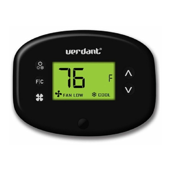
Summary of Contents for Verdant VX-TW
- Page 1 VX-TW VX Series Wireless Thermostat with an Occupancy Sensor INSTALLATION MANUAL JUNE 26, 2017...
-
Page 2: Table Of Contents
Table of Contents Introduction ....................4 Thermostat Installation ................6 Pairing the Thermostat and the Control Card ..........7 Installing the Wireless Control Card ............8 Mounting the thermostat to the wall ............9 Thermostat Configuration ................. 10 Setting the thermostat clock ...............11 Entering the room number ................. -
Page 3: Introduction
Introduction NOTICE Verdant VX Series Energy Management Thermostats for the hospitality industry deliver unprecedented energy savings without compromising FOR INSTALLATION OF NETWORKING THERMOSTATS WITH REMOTE MANAGEMENT, REFER TO THE “VX-TW NETWORK guest comfort. INSTALLATION” MANUAL. An integrated occupancy sensor uses a combination of motion and LOGIN TO THE REMOTE MANAGEMENT WEBSITE TO CONFIRM thermal sensing technologies for accurate occupancy detection. -
Page 4: Pairing The Thermostat And The Control Card
Before You Begin Before You Begin Pairing the Thermostat and the Control Card Determine the appropriate installation location for the thermostat. ➤ The Thermostat and Control Card must be paired in order to operate together. Once paired, the thermostat cannot be used with another THE THERMOSTAT SHOULD FACE THE BED AREA OF THE ROOM. -
Page 5: Installing The Wireless Control Card
Thermostat Installation Thermostat Installation Installing the Wireless Control Card Power Off the HVAC unit; ➤ Connect the control card to the thermostat terminals on the HVAC ➤ unit - refer to the Wiring Table to determine proper connections. Mount the control card inside of the HVAC unit. ➤... -
Page 6: Thermostat Configuration
Thermostat Configuration Thermostat Configuration Setting the thermostat clock Once the thermostat is powered, thermostat configuration settings will appear on the thermostat screen. In order to properly operate the HVAC unit: ➤ Set the thermostat clock; ➤ Enter the room number; Configure the equipment settings;... -
Page 7: Entering The Room Number
Thermostat Configuration Thermostat Configuration Entering the room number Configuring the Equipment Settings - Compressor Type COMPRESSOR TYPE Enter the room number by changing the digits on the screen. Leading Use the “Up” and “Down” buttons to change the compressor type by ➤... -
Page 8: Configuring The Equipment Settings - Electric Heat
Thermostat Configuration Thermostat Configuration Configuring the Equipment Settings - Electric Heat Configuring the Equipment Settings - Reversing Valve ELECTRIC HEAT REVERSING VALVE Use the “Up” and “Down” buttons to change the Electric Heat setting Use the “Up” and “Down” buttons to change the Reversing Valve ➤... -
Page 9: Configuring The Energy Saving Settings
Thermostat Configuration Thermostat Configuration Configuring the Energy Saving Settings Testing the thermostat Following the thermostat configuration, test if the thermostat is controlling the HVAC unit. ➤ Press the “Power” button to turn the thermostat ON; ➤ Press the “Down” button to change the temperature set point below the current room temperature to confirm that the thermostat initiates air conditioning. -
Page 10: Thermostat Maintenance
Thermostat Maintenance Troubleshooting Replacing Thermostat Batteries Error Codes ERR 1 The low battery indicator will be displayed on the thermostat screen Thermostat Temperature Sensor Hardware Defect when it is necessary to replace batteries in the thermostat. ERR 2 Thermostat Radio Hardware Defect Under normal operating conditions, new brand-name alkaline batteries will last for a period of approximately one (1) year. -
Page 11: Appendix 1 - Energy Saving Presets
Troubleshooting APPENDIX 1 - Energy Saving Presets The Thermostat is not controlling the HVAC unit. Level Level Level Level Level Level Check if the HVAC unit is set to “External Thermostat” (Class 2) mode. Fan Control Mode AUTO AUTO AUTO AUTO AUTO AUTO Verify the status of the red light on the Wireless Control Card;... -
Page 12: Appendix 2 - Glossary
Should a covered defect occur during the warranty period and Customer notifies Verdant, between 1st stage heating temperature and Customer’s sole and exclusive remedy will be, at Verdant’s sole option and expense, to repair room temperature before the 2nd stage heating “Setback Set points On”... -
Page 13: Technical Specifications
6,581,846; 6,578,770; 7,838,803; 7,841,542; D556,061; D518,744; RE40,437; CANADIAN PATENTS: 2,633,113; 2,633,200; OTHER PATENTS PENDING. Verdant Environmental Technologies, Inc. reserves the right to make changes, without notice, in design or © Verdant Environmental Technologies, Inc. 2017. components. Product appearance may vary.


Need help?
Do you have a question about the VX-TW and is the answer not in the manual?
Questions and answers