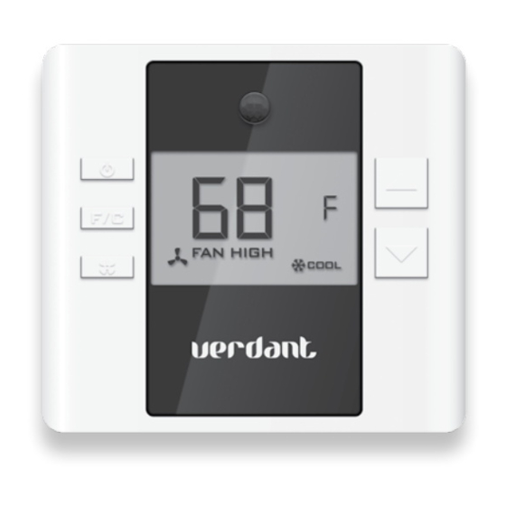
Verdant VX Series Installation Manual
Thermostat with an occupancy sensor
Hide thumbs
Also See for VX Series:
- Instruction manual (23 pages) ,
- Installation manuals (27 pages) ,
- Installation manual (19 pages)

Related Manuals for Verdant VX Series


Summary of Contents for Verdant VX Series
- Page 1 VX Series Thermostat with an Occupancy Sensor INSTALLATION MANUAL MAY 31, 2016...
-
Page 3: Table Of Contents
Table of Contents Introduction ....................5 Before You Begin ..................8 Programming a Thermostat with a Network Programmer ......9 Thermostat Installation ................10 Thermostat Configuration ................11 Setting the thermostat clock ..............12 Entering the room number ................. 13 Configuring the Equipment Settings - Compressor Type ......14 Configuring the Equipment Settings - Electric Heat ........15 Configuring the Equipment Settings - Reversing Valve ......16 Configuring the Energy Saving Settings ............ - Page 4 Table of Contents 18 – MAXIMUM SET POINT ................. 38 19 – TEMPERATURE CONTROL MODE ............39 20 – AUTO CHANGEOVER SET POINT OFFSET ...........40 21 – SETBACK SET POINTS / AUTO-RESTORE ..........41 22 – AUTOMATIC HUMIDITY CONTROL † ....................42 22 –...
-
Page 5: Introduction
Introduction Verdant VX Series Energy Management Thermostats for the hospitality industry deliver unprecedented energy savings without compromising guest comfort. Integrated occupancy sensor uses a combination of motion and thermal sensing technologies for accurate occupancy detection. Reliable occupancy detection allows saving energy when rooms are unoccupied. - Page 7 THERMOSTAT(S) HAVE CONNECTED TO THE WIRELESS NETWORK AND THE REMOTE MANAGEMENT WEBSITE . IF INSTALLED THERMOSTAT(S) ARE NOT CONNECTING TO THE NETWORK AND DO NOT APPEAR ON THE VERDANT’S REMOTE MANAGEMENT WEBSITE WITH THE CORRECT ROOM NUMBER, STOP THE INSTALLATION AND CONTACT VERDANT TECHNICAL...
-
Page 8: Before You Begin
Before You Begin Determine the appropriate installation location for the thermostat. ➤ THERMOSTAT SHOULD FACE THE BED AREA OF THE ROOM. THERMOSTAT MUST NOT BE INSTALLED NEAR OR ON METAL STRUCTURES OR SURFACES INCLUDING METAL AIR DUCTING THAT MAY BE IN THE WALL. METAL STRUCTURES AND SURFACES SIGNIFICANTLY REDUCE THE RANGE OF THE WIRELESS SIGNAL. -
Page 9: Programming A Thermostat With A Network Programmer
Before You Begin Programming a Thermostat with a Network Programmer In case of Network Installation with Remote Management, the thermostat must be programmed with a Network Programmer specific to the property before the installation. Thermostat must not be powered during the programming procedure.. Plug one programmer connector into the thermostat;... -
Page 10: Thermostat Installation
Thermostat Installation Mounting the thermostat to the wall Power of the HVAC unit; ➤ Remove the thermostat cover; ➤ Connect the thermostat wires to the supplied Wiring Harness - refer ➤ to the Wiring Table to determine proper connections; Plug in the Wiring Harness into to the thermostat; ➤... -
Page 11: Thermostat Configuration
Thermostat Configuration Once the thermostat is powered, thermostat configuration settings will appear on the thermostat screen. In order to properly operate the PTAC unit: Set the thermostat clock; ➤ Enter the room number; ➤ Configure the equipment settings; ➤ Select Energy Savings Preset; ➤... -
Page 12: Setting The Thermostat Clock
Thermostat Configuration Setting the thermostat clock HOURS MINUTES Set the thermostat clock to current time in 24h (Military Time) format. Use the “Up” and “Down” buttons to set the hours; ➤ Press the “Fan” button to advance to the minutes setting; ➤... -
Page 13: Entering The Room Number
Thermostat Configuration Entering the room number Enter the room number by changing the digits on the screen. Leading zeros “0” preceding other digits will be ignored, i.e. Room number “123” should be entered as “00123”. Use the “Up” and “Down” buttons to change the digit; ➤... -
Page 14: Configuring The Equipment Settings - Compressor Type
Thermostat Configuration Configuring the Equipment Settings - Compressor Type COMPRESSOR TYPE Use the “Up” and “Down” buttons to change the compressor type by ➤ changing the first digit; No Compressor Heat Pump Air Conditioner Press the “Fan” button to advance to the next setting; ➤... -
Page 15: Configuring The Equipment Settings - Electric Heat
Thermostat Configuration Configuring the Equipment Settings - Electric Heat ELECTRIC HEAT Use the “Up” and “Down” buttons to change the Electric Heat setting ➤ by changing the second digit; No Electric Heat Electric Heat Press the “Fan” button to advance to the next setting; ➤... -
Page 16: Configuring The Equipment Settings - Reversing Valve
Thermostat Configuration Configuring the Equipment Settings - Reversing Valve REVERSING VALVE Use the “Up” and “Down” buttons to change the Reversing Valve ➤ setting by changing the third digit; O/B contact is energized to cool; O/B contact is energized to heat; Refer to the PTAC unit documentation to determine the correct reversing valve setting. -
Page 17: Configuring The Energy Saving Settings
Thermostat Configuration Configuring the Energy Saving Settings Use the “Up” and “Down” buttons to select the Energy Saving preset: ➤ E-0* Energy Savings Off - No Temperature Setback; Lowest Energy Savings; Lower Energy Savings; Standard Energy Savings; Higher Energy Savings; Highest Energy Savings;... -
Page 18: Testing The Thermostat
Thermostat Configuration Testing the thermostat Following the thermostat configuration, test if the thermostat is controlling the PTAC unit. Press the “Power” button to turn the thermostat ON; ➤ Press the “Down” button to change the temperature set point below ➤ the current room temperature to confirm that the thermostat initiates air conditioning. -
Page 19: Accessing The Thermostat Settings
Custom Energy Savings Settings If you don’t want to use the one of the energy saving presets, you can enter custom energy savings settings. Accessing the Thermostat Settings Press and hold the “Configuration” button until the first thermostat ➤ settings screen appears. The thermostat must be turned on to access the thermostat settings. -
Page 20: Using The Thermostat Settings Screens
Custom Energy Savings Settings Using the Thermostat Settings Screens SETTING VALUE SCREEN NUMBER Use the “Up” and “Down” buttons to change the setting; ➤ Press the “F/C” button to advance to the next setting; ➤ Press the “Fan” button to return to the previous setting; ➤... -
Page 21: Fan Control Mode
Custom Energy Savings Settings 01 – FAN CONTROL MODE Select Fan Control Mode: MANUAL - guest can select automatic or continuous fan mode; 01 * AUTOMATIC - fan runs only when there is a demand for heating or air conditioning; Indicates default setting;... -
Page 22: St Stage Differential - Heat
Custom Energy Savings Settings 02 – 1 STAGE DIFFERENTIAL - HEAT 02-30 (0.2°F - 3.0°F; 0.5°F* default setting) Select the number of degrees the thermostat has to sense between the automatic changeover temperature for heat and the room temperature before a call for the 1st stage heating is initiated. -
Page 23: Nd Stage Differential - Heat
Custom Energy Savings Settings 03 – 2 STAGE DIFFERENTIAL - HEAT 10-20 (1.0°F - 2.0°F*; 2.0°F* default setting) Select the difference between 1st stage heating and 2nd stage heating initiation. -
Page 24: 1St Stage Differential - Cool
Custom Energy Savings Settings 04 – 1ST STAGE DIFFERENTIAL - COOL 02-30 (0.2°F - 3.0°F; 0.5°F* default setting) Select the number of degrees the thermostat has to sense between the automatic changeover temperature for cool and the room temperature before a call for the 1st stage cooling is initiated. -
Page 25: Incidental Occupancy Threshold
Custom Energy Savings Settings 05 – INCIDENTAL OCCUPANCY THRESHOLD 00-60 (05* default setting) Select the minimum period of time (in minutes) for which occupancy needs to be detected to enter the guest occupancy mode. When occupancy is detected, thermostat will switch to occupied mode for a duration of “Incidental Occupancy Threshold”... -
Page 26: Night Occupancy Threshold
Custom Energy Savings Settings 06 – NIGHT OCCUPANCY THRESHOLD 00-60 (01* default setting) Select the minimum period of time (in minutes) for which occupancy needs to be detected in order to consider the room occupied during the “Night Occupancy”period. When occupancy is detected during the “Night Occupancy Period”... -
Page 27: Forced 2Nd Stage Heating
Custom Energy Savings Settings 07 – FORCED 2ND STAGE HEATING 00-60 (30* default setting) Select a number of minutes 1st stage heating will run before 2nd stage heating is automatically initiated if the guest set point is not reached and the 2nd stage heating is not initiated through differential settings. -
Page 28: Night Occupancy Start
Custom Energy Savings Settings 08 – NIGHT OCCUPANCY START 00-23 (21* default setting) Select the start time (in hours - 24-hour clock) for “Night Occupancy” If occupancy is detected for a period of time longer than the “Night Occupancy Threshold” during “Night Occupancy” period, the thermostat will disable the occupancy sensor and consider the room occupied until the end of the “Night Occupancy”... -
Page 29: Night Occupancy End
Custom Energy Savings Settings 09 – NIGHT OCCUPANCY END 00-23 (09* default setting) Select the time (in hours - 24-hour clock) for “Night Occupancy” to end. The time of day the “Night Occupancy” ends and the thermostat switches back to the room sensing settings chosen in the other occupancy modes. -
Page 30: Temperature Recovery Time
Custom Energy Savings Settings 10 – TEMPERATURE RECOVERY TIME 00-60 (25* default setting) Select the maximum time allowed for a PTAC unit to attain temperature as defined by Heat and Cool “Recovery Temperature”. “Temperature Recovery Time” selected here and the actual temperature recovery ability of the PTAC unit are used to calculate setback temperatures. -
Page 31: Recovery Temperature - Heat
Custom Energy Savings Settings 11 – RECOVERY TEMPERATURE - HEAT 62-82 (67°F* default setting) Select the room temperature in °F that a PTAC unit will have to attain within the selected “Temperature Recovery Time” when there is a need for heating. -
Page 32: Temperature Setback Delay - Heat
Custom Energy Savings Settings 12 – TEMPERATURE SETBACK DELAY - HEAT 00-120 (20* default setting) Select the time delay (in minutes) for which the room that is in the guest occupancy mode needs to be unoccupied before the temperature setback is initiated. This feature prevents initiating temperature setback prematurely while the guest is still in the room but in an area where occupancy cannot be detected by the occupancy sensor. -
Page 33: Minimum Setback Temperature
Custom Energy Savings Settings 13 – MINIMUM SETBACK TEMPERATURE 52-72 (64°F* default setting) Select the “Minimum Setback Temperature” in °F. Setback temperature is calculated by measuring PTAC unit’s ability to attain “Recovery Temperature - Heat” within “Temperature Recovery Time”. If recovery is disabled (“Temperature Recovery Time” is set to “0”) or if setback temperatures have not yet been calculated, the “Minimum Setback Temperature”... -
Page 34: Temperature Setback Delay - Cool
Custom Energy Savings Settings 14 – TEMPERATURE SETBACK DELAY - COOL 00-120 (20* default setting) Select the time delay (in minutes) for which the room that is in the guest occupancy mode needs to be unoccupied before the temperature setback is initiated. This feature prevents initiating temperature setback prematurely while the guest is still in the room but in an area where occupancy cannot be detected by the occupancy sensor. -
Page 35: Maximum Setback Temperature
Custom Energy Savings Settings 15 – MAXIMUM SETBACK TEMPERATURE 72-92 (78°F* default setting) Select the “Maximum Setback Temperature” in °F. Setback temperature is calculated by measuring PTAC unit’s ability to attain “Recovery Temperature - Cool” within “Temperature Recovery Time”. If recovery is disabled (“Temperature Recovery Time” is set to “0”) or if setback temperatures have not yet been calculated, the “Maximum Setback Temperature”... -
Page 36: Recovery Temperature - Cool
Custom Energy Savings Settings 16 – RECOVERY TEMPERATURE - COOL 62-82 (74°F* default setting) Select the room temperature in °F that a PTAC unit will have to attain within the selected “Temperature Recovery Time” when there is a need for air conditioning. -
Page 37: Minimum Set Point
Custom Energy Savings Settings 17 – MINIMUM SET POINT 64-84 (66°F* default setting) Select the minimum set point in °F that a guest can select. -
Page 38: Maximum Set Point
Custom Energy Savings Settings 18 – MAXIMUM SET POINT 60-82 (78°F* default setting) Select the maximum set point in °F that a guest can select. -
Page 39: Temperature Control Mode
Custom Energy Savings Settings 19 – TEMPERATURE CONTROL MODE Select Temperature Control Mode: MANUAL - Allows users to select HEAT only or COOL only temperature control mode to maintain the room temperature; 01 * AUTOMATIC - Thermostat automatically turns on heating or air conditioning to maintain the room temperature at the selected temperature set point;... -
Page 40: Auto Changeover Set Point Offset
Custom Energy Savings Settings 20 – AUTO CHANGEOVER SET POINT OFFSET (DEAD BAND) 00-04 (01°F* default setting) Select the difference between the guest- selected set point and the heat and the cool set point when the thermostat is in the automatic temperature control mode. This value plus the 1st stage differential defined in steps 02 and 04, defines the temperature at which the thermostat would automatically change heating/cooling modes. -
Page 41: Setback Set Points / Auto-Restore
Custom Energy Savings Settings 21 – SETBACK SET POINTS / AUTO-RESTORE When room is unoccupied and the thermostat is in the setback mode or turned off, it will NOT maintain the temperature between heat and cool setback set points; When guest enters the room, the thermostat will be turned off - it will not automatically restore the most recent guest settings;... -
Page 42: Automatic Humidity Control
Custom Energy Savings Settings 22 – AUTOMATIC HUMIDITY CONTROL † Disable automatic humidity control; 01 * Enable automatic humidity control; When “Automatic Humidity Control” is enabled, thermostat will turn on air conditioning in an unoccupied room when humidity raises above 60% and room temperature is above 72°F until either room humidity is below 55% or room temperature is below 72°F;... -
Page 43: Temperature Calibration
Custom Energy Savings Settings 22 – TEMPERATURE CALIBRATION -5.0 – 5.0 (0.0°F* default setting) Calibrate the temperature display : -5.0°F - 5.0°F. -
Page 44: Relay Options
Relay Options ACCESSING RELAY OPTIONS Press and hold the “Configuration” button; ➤ Release the “Configuration” button when the first thermostat ➤ settings screen appears; Press and release the “Configuration” button again to access the ➤ Relay Settings The thermostat must be turned on to access the thermostat settings. CONFIGURATION BUTTON NOTE: Use the “Configuration”... -
Page 45: Reverse Relay Operation
Relay Options 1 – REVERSE RELAY OPERATION Select Relay Operation for Y, W, O/B outputs: NORMALLY CLOSED - Thermostat activates the relay to energize the output when there is a call for it; Output is not energized when idle. NORMALLY OPEN - Thermostat de-activates the relay to de-energize the output when there is a call for it;... -
Page 46: Cooling Only "Spdt" Valve Control
Relay Options 2 – COOLING ONLY “SPDT” VALVE CONTROL Enable or disable relay control for Single-Pole Double-Throw (SPDT) valve in a cooling only system that requires separate signals for opening and closing the valve: DISABLED ENABLED Indicates default setting; When this mode is enabled, thermostat will energize the “Y” output to open the valve when there is a request for cooling and energize the “W”... -
Page 47: Heat Pump Relay Mode
Relay Options 3 – HEAT PUMP RELAY MODE Select the Heat Pump relay mode: PTAC PTAC MODE - Thermostat will energize the reverse valve (“O/B”) output only when “Y” output is energized. The thermostat will energize the “O/B” output in the compressor heat or cool mode based on the “Reversing Valve”... -
Page 48: Troubleshooting
Troubleshooting Error Codes ERR 1 Thermostat Temperature Sensor Hardware Defect ERR 2 Thermostat Radio Hardware Defect ERR 3 Thermostat Radio Software Defect ERR 5 Thermostat Memory Defect... -
Page 49: Appendix 1 - Energy Saving Presets
APPENDIX 1 - Energy Saving Presets Level Level Level Level Level Level AUTO AUTO AUTO AUTO AUTO AUTO Fan Control Mode 1st Stage Differential Heat 2nd Stage Differential Heat 1st Stage Differential Cool Guest Occupancy Threshold Night Occupancy Threshold Force 2nd Stage Heating After Night Occupancy Start Night Occupancy End Recovery Time... -
Page 50: Appendix 2 - Glossary
APPENDIX 2 - Glossary “Automatic Fan Control Mode” - fan runs only “Incidental Occupancy Threshold” - the minimum when there is a demand for heating or cooling; period of time (in minutes) for which occupancy needs to be detected in order to enter the “Guest “Manual Fan Control Mode”... -
Page 51: Warranty Information
Should a covered defect occur during the warranty period and Customer notifies Verdant, Customer’s sole and exclusive remedy will be, at Verdant’s sole option and expense, to repair or replace the product. Replacement products or parts may be new or reconditioned or a comparable version of the defective item. -
Page 52: Technical Specifications
6,581,846; 6,578,770; 7,838,803; 7,841,542; D556,061; D518,744; RE40,437; CANADIAN PATENTS: 2,633,113; 2,633,200; OTHER PATENTS PENDING. Verdant Environmental Technologies, Inc. reserves the right to make changes, without notice, in design or © Verdant Environmental Technologies, Inc. 2015. components. Product appearance may vary.
Need help?
Do you have a question about the VX Series and is the answer not in the manual?
Questions and answers