Verdant VX Series Instruction Manual
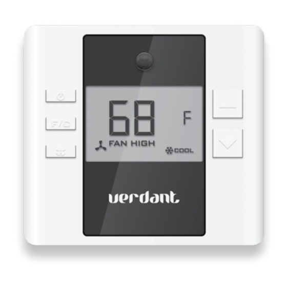
Vx series, wireless thermostat with occupancy sensor
Hide thumbs
Also See for VX Series:
- Installation manual (52 pages) ,
- Installation manuals (27 pages) ,
- Installation manual (19 pages)
Table of Contents
Advertisement
Advertisement
Table of Contents

Related Manuals for Verdant VX Series


Summary of Contents for Verdant VX Series
- Page 1 VX SERIES Wireless Thermostat with Occupancy Sensor INSTRUCTION MANUAL...
-
Page 2: Table Of Contents
Table of Contents Thermostat Installation ................7 Installing the Wireless Control Card ............8 Mounting the thermostat to the wall ............9 Thermostat Configuration ................. 10 Setting the thermostat clock ...............11 Entering the room number ................. 12 Configuring the Equipment Settings - Compressor Type ......13 Configuring the Equipment Settings - Electric Heat ........14 Configuring the Equipment Settings - Reversing Valve ......15 Configuring the Energy Saving Settings ............16... - Page 3 Table of Contents Troubleshooting ..................39 Thermostat is not controlling the PTAC unit..........39 Error Codes ....................40 APPENDIX 1 ....................41 Warranty ....................42 Technical Specifications ................44...
-
Page 4: Thermostat Installation
Thermostat Installation BEFORE YOU BEGIN DETERMINE THE APPROPRIATE INSTALLATION LOCATION FOR THE THERMOSTAT. THE THERMOSTAT SHOULD FACE THE BED AREA OF THE ROOM. After the installation, follow the “Thermostat Configuration” Instructions to correctly configure the thermostat. For installation of a networking thermostat with remote management, refer to the “Network Installation”... -
Page 5: Installing The Wireless Control Card
Thermostat Installation Thermostat Installation BEFORE YOU BEGIN: Consult PTAC manufacturer’s documentation or use Wiring Table - 24V AC Wiring Table - 24V DC a voltmeter to determine if the PTAC unit outputs AC or DC power (24V). Wire Terminal Terminal Wire Terminal Terminal... -
Page 6: Thermostat Configuration
Thermostat Configuration Thermostat Configuration Setting the thermostat clock Once the thermostat is powered, thermostat configuration settings will appear on the thermostat screen. In order to properly operate the PTAC unit: ➤ Set the thermostat clock; ➤ Enter the room number; Configure the equipment settings;... -
Page 7: Entering The Room Number
Thermostat Configuration Thermostat Configuration Entering the room number Configuring the Equipment Settings - Compressor Type Enter the room number by changing the digits on the screen. Leading ➤ Use the “Up” and “Down” buttons to change the compressor type by zeros “0”... -
Page 8: Configuring The Equipment Settings - Electric Heat
Thermostat Configuration Thermostat Configuration Configuring the Equipment Settings - Electric Heat Configuring the Equipment Settings - Reversing Valve ➤ Use the “Up” and “Down” buttons to change the Electric Heat setting ➤ Use the “Up” and “Down” buttons to change the Reversing Valve by changing the second digit;... -
Page 9: Configuring The Energy Saving Settings
Thermostat Configuration Thermostat Configuration Configuring the Energy Saving Settings Testing the thermostat Following the thermostat configuration, test if the thermostat is controlling the PTAC unit. ➤ Press the “Power” button to save the Thermostat Configuration and start using the thermostat; Press the “Power”... -
Page 10: Thermostat Settings
Thermostat Settings Thermostat Settings Accessing the Thermostat Settings FAN ENERGY SAVINGS Thermostat Settings allow customizing the energy savin settings. To access the thermostat settings: Press and hold the “Configuration” button until the first thermostat ➤ settings screen (“00”) appears on the thermostat. The thermostat must be turned on to access the thermostat settings. -
Page 11: St Stage Differential - Heat
Thermostat Settings Thermostat Settings STAGE DIFFERENTIAL - HEAT STAGE DIFFERENTIAL - HEAT 02-30 10-20 (0.2°F - 3.0°F; 0.5°F*) Select the difference between temperature (1.0°F - 2.0°F*) Select the difference between 1st STAGE heating setpoint and room temperature before 1st STAGE heating is and 2nd STAGE heating initiation. -
Page 12: 1St Stage Differential - Cool
Thermostat Settings Thermostat Settings 1ST STAGE DIFFERENTIAL - COOL INCIDENTAL OCCUPANCY THRESHOLD 02-30 00-60 (0.2°F - 3.0°F; 0.5°F*) Select the difference between temperature (05*) Select the minimum period of time (in minutes) setpoint and room temperature before 1st STAGE cooling is for which occupancy needs to be detected to enter guest initiated. -
Page 13: Forced 2Nd Stage Heating
Thermostat Settings Thermostat Settings NIGHT OCCUPANCY THRESHOLD FORCED 2ND STAGE HEATING 00-60 00-60 (01*) Select the minimum period of time (in minutes) for which (30*) Select a number of minutes 1st STAGE heating will run occupancy needs to be detected in order to consider the room before 2nd STAGE heating is automatically initiated if the occupied during the “Night Occupancy”period. -
Page 14: Night Occupancy Start
Thermostat Settings Thermostat Settings NIGHT OCCUPANCY START NIGHT OCCUPANCY END 00-23 00-23 (21*) Select the start time (in hours - 24-hour clock) for “Night (09*) Select the end time (in hours - 24-hour clock) for “Night Occupancy” Occupancy” If occupancy is detected for a period of time longer than the If occupancy is detected for a period of time longer than the “Night Occupancy Threshold”... -
Page 15: Temperature Recovery Time
Thermostat Settings Thermostat Settings TEMPERATURE RECOVERY TIME RECOVERY TEMPERATURE - HEAT 00-60 62-82 (25*) Select the maximum time allowed for a PTAC unit to (66°F) Select the room temperature in °F that a PTAC unit will attain temperature as defined by Heat and Cool “Recovery have to attain within the selected “Temperature Recovery Temperature”;... -
Page 16: Temperature Setback Delay - Heat
Thermostat Settings Thermostat Settings TEMPERATURE SETBACK DELAY - HEAT MINIMUM SETBACK TEMPERATURE 00-120 52-72 (20*) Select the time delay (in minutes) before the thermostat (64°F) Select the “Minimum Setback Temperature” in °F. will initiate the temperature setback and allow the room temperature to drop to the setback temperature after the Setback temperature is calculated by measuring PTAC unit’s room becomes unoccupied. -
Page 17: Temperature Setback Delay - Cool
Thermostat Settings Thermostat Settings TEMPERATURE SETBACK DELAY - COOL MAXIMUM SETBACK TEMPERATURE 00-120 72-92 (20*) Select the time delay (in minutes) before the thermostat (78°F) Select the “Maximum Setback Temperature” in °F. will initiate the temperature setback and allow the room temperature to raise to the setback temperature after the Setback temperature is calculated by measuring PTAC room becomes unoccupied... -
Page 18: Recovery Temperature - Cool
Thermostat Settings Thermostat Settings RECOVERY TEMPERATURE - COOL MINIMUM SETPOINT 62-82 64-84 (75°F) Select the room temperature in °F that a PTAC unit will (65°F) Select the minimum setpoint in °F that a guest can have to attain within the selected “Temperature Recovery select. -
Page 19: Maximum Setpoint
Thermostat Settings Thermostat Settings MAXIMUM SETPOINT AUTO CHANGEOVER SETPOINT OFFSET 60-82 00-04 (80°F) Select the maximum setpoint in °F that a guest can (01°F*) Select the difference between the guest-selected select. setpoint and the heat and cool setpoints. This feature allows to configure the minimum difference between heat and cool setpoints in order to avoid excessive use of the compressor. -
Page 20: Setback Setpoints / Auto-Restore
Thermostat Settings Troubleshooting SETBACK SETPOINTS / AUTO-RESTORE Thermostat is not controlling the PTAC unit. Verify the status of the red light on the Wireless Control Card; ➤ The red light is off The control card is not powered. Verify the Wireless Control Card is properly wired to the PTAC unit;... -
Page 21: Error Codes
Troubleshooting APPENDIX 1 Error Codes Level Level Level Level Level Level ERR 1 Thermostat Temperature Sensor Hardware Defect Fan Operation Mode Auto Auto Auto Auto Auto Auto ERR 2 Thermostat Radio Hardware Defect Minimum Setpoint 64°F 65°F 66°F 67°F 68°F 68°F Maximum Setpoint 84°F... -
Page 22: Warranty
Replacement products or parts may be new or reconditioned or a comparable version of the defective item. Verdant warrants any replaced product or part for a period of ninety (90) days from shipment, or through the end of the original warranty, whichever is longer. -
Page 23: Technical Specifications
INCLUDING INTERFERENCE THAT MAY CAUSE UNDESIRED OPERATION. PURSUANT TO PART 15.21 OF THE FCC RULES, ANY CHANGES OR MODIFICATIONS TO THIS EQUIPMENT NOT EXPRESSLY APPROVED BY VERDANT ENVIRONMENTAL TECHNOLOGIES, INC. MAY VOID VOID THE USER’S AUTHORITY TO OPERATE THE EQUIPMENT.
Need help?
Do you have a question about the VX Series and is the answer not in the manual?
Questions and answers