Table of Contents
Advertisement
Quick Links
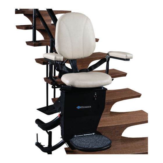
helix curved Stair Lift
Installation & Service Manual
WARNING! StRIct AdheReNce to theSe INStAllAtIoN INStRuctIoN IS RequIRed to promote the safety of
those installing this product, as well as that of those ultimately using the lift for its intended purpose. Any deviation
from these instructions will void the limited Warranty that accompanies the product. Additionally, any party install-
ing the product who deviates from the Installation Instructions shall be taken to agree to INdeMNIFY, SAVe ANd
hold hARMleSS the manufacturer from any and all loss, liability or damage, including attorney fees, that might arise
out of, or in connection with, such deviation.
Advertisement
Table of Contents

Related Manuals for Harmar Mobility Helix Curved Stair Lift


Summary of Contents for Harmar Mobility Helix Curved Stair Lift
- Page 1 Stair Lift Installation & Service Manual WARNING! StRIct AdheReNce to theSe INStAllAtIoN INStRuctIoN IS RequIRed to promote the safety of those installing this product, as well as that of those ultimately using the lift for its intended purpose. Any deviation from these instructions will void the limited Warranty that accompanies the product.
-
Page 2: Table Of Contents
Manual to the owner of the lift before it is put into service. Any alterations to the equipment without written authorization by the manufacturer may void the warranty. Device Name: harmar helix curved Stair lift Indications for Use: the intended use of the helix Stair lift is to assist transfers of patients or mobility... -
Page 3: Preliminary Checks
• Rails • complete Seat Assembly • Power Supply • Wires Figure 3-1 • Bag of Screws • Pipe and Support caps Figure 3-2 helix curved Stair lift - Installation & Service Manual 2014 Part Number: 630-00008- Rev A... -
Page 4: Tools Required
Preparation tooLS reqUIreD • Wire Stripper/crimper • Ratcheting Allen Wrench (metric) Fish tape • Snap ring pliers • • drill extension Bit • drill and drill Bits • Mounting Screws could be needed, • emery/Sandpaper based on flooring • lightweight Grease •... -
Page 5: Figure
Figure 5-5 [Figure 5-5] helix curved Stair lift - Installation & Service Manual 2014 Part Number: 630-00008- Rev A... -
Page 6: Figure 6-1 –
Installation Slide the pipes together one at a time starting at the bottom in the order indicated on the label, in order. Install on the Stair Supports. [Figure 6-1 – 6-3] A ratcheting strap can be used to help pull the rails together. - Page 7 Installation 9. rail Leveling/alignment: using the angle meter, set the rail to the correct angles and check the drawing to verify that all clearances are correct. 10. Supports Recheck angles then, using the appropriate hardware, attach the Supports to the stairs, starting at a corner. Firmly set the supports to the rail with set screw.
-
Page 8: Wiring
Wiring & chassis Never lay unit on its back. WarNING! 11. Drive Unit/Seat open front of chassis, by removing 4 allen screws on shroud. Set chassis upright on base. Route wire of seat thru seat mounting hole. Install seat [Figures 8-1 & 8-2]. Install at 45° from base so the seat stop does not hit the limit switch. -
Page 9: Figure
Wiring & chassis Install batteries. connect battery wire. [Figure 9-1] Replace Shroud Use caution when handling battery. Figure 9-1 caUtIoN 16. Install chassis. Bottom roller position. ensure charging point is on the bottom. [Figure 9-2] ensure charging fingers are set as low as possible caUtIoN to ensure there is no inter- Figure 9-2... - Page 10 Installation Figure 10-1 Figure 10-2 Figure 10-3 − mid station landing the unit will stop on this when driven with the wireless remote. It will stop for 5 to 6 seconds then continue. It will not stop with the joystick. charging Station alignment When assembly is complete, align both charging Stations.
-
Page 11: Final Checks
Final checks Wireless remote reprogramming the wireless controllers are shipped preprogrammed for Button the seat. on the wireless press the little button on the board then hold the up button on the remote for 3 to 4 seconds and it should learn the remote. Final checks Figure 11-1 Before putting the lift into operation for the user verify the following:... -
Page 12: Technical Specifications
technical Specifications technical Specifications Weight capacity: ..........350 lbs. track (rail) type: . -
Page 13: Wiring Diagram
Wiring Diagram Battery Battery helix curved Stair lift - Installation & Service Manual 2014 Part Number: 630-00008- Rev A...
Need help?
Do you have a question about the Helix Curved Stair Lift and is the answer not in the manual?
Questions and answers