Table of Contents
Advertisement
IDS X-Series v2.7
Change Guide
Introduction
With X-Series v2.7 comes the new Xwave
will ensure your detectors are properly supervised.
2
Xwave
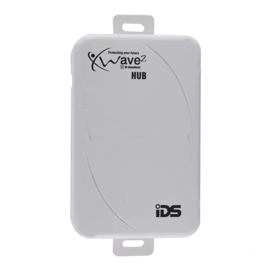
The IDS X-Series Bi-directional Xwave
and two programmable outputs. The hub can also learn up to 16 Xwave
transmitters. It is wired to the X-Series panel in the same way as all other peripheral devices, on
the keypad bus.
1. Installation
Xwave
2
works on the IDS X-Series panels, versions 2.7 and above.
1.1.
Addressing
To address the Xwave
2
Hub, set the dipswitches as per the table below. Depending on what
address is used on the Hub will determine the zone numbers it uses.
Note: The unit must be powered down when selecting the unit's address.
Binary value on switch
Dipswitch 1 up
Dipswitch 2 up
Dipswitches 1 + 2 up
Dipswitch 3 up
Dipswitch 6 up
2
. The latest in bi-directional wireless technology that
2
Hub offers an additional 16 wireless supervised zones
Hub zones
3 second button panic disabled
2
Bi-directional remote
1 -16
17 - 32
33 – 48
49 - 64
Advertisement
Table of Contents

Subscribe to Our Youtube Channel
Related Manuals for IDS Xwave2


Summary of Contents for IDS Xwave2
- Page 1 It is wired to the X-Series panel in the same way as all other peripheral devices, on the keypad bus. 1. Installation Xwave works on the IDS X-Series panels, versions 2.7 and above. 1.1. Addressing To address the Xwave Hub, set the dipswitches as per the table below.
- Page 2 1.2. Xwave and Other Wireless Expanders The Xwave Hub can work in conjunction with Xwave/Duevi. You can either have the Xwave operating with a different address to an Xwave/Duevi Expander using a different zone range or, if needed, with the same address as an Xwave/Duevi Expander in which case it will share the zone range.
- Page 3 Trouble Pulse Number: Pulse Error Description Dead Keypad Bus There is no activity on the bus. Not Registered The hub has not been able or is waiting for the X-Series panel to be registered. Not Receiving The hub is registered on the bus but is not receiving messages. Messages Invalid Dipswitches Dipswitches are set to an unrecognised setting.
- Page 4 Xwave Configuration Settings Due to the intelligence of Xwave2 you can now change the detectors configuration settings, LED and Pulse count, from the X-Series panel. Go to location 260 sub location 5, select the zone and enable/disable the bitmaps according to your needs.
- Page 5 3.3. Adding the Remote Transmitter to a User code To add a bi-directional Xwave remote transmitter to a user code. 1. Enter the Master User Menu 2. Scroll to menu [Add Bidir Remote] or enter [1][6][*] 3. Enter the Hub that you are teaching the remote too 4.
- Page 6 Function Parameter Description Stay & Go Partition Will arm the allocated partition in stay & Go in stay profile 3 and then allow Prof3 Number you to scroll to the next available profile if one is configured. Stay & Go Partition Will arm the allocated partition in stay &...
- Page 7 Example to query the arm status of the alarm using the default button assignments: Press button 1 (Function button) then button 3 (Arm/Disarm button). The led will flash white indicating transmitting message then blue if the alarm is ready to arm, red if armed or flash red if armed but a violation has occurred.
- Page 8 The module has one programmable output, the address of the output is based on what zone the I/O Module is learned to. Zone Range I/O Module PGM Address 1 – 4 5 – 8 9 – 12 13 – 16 17 –...
Need help?
Do you have a question about the Xwave2 and is the answer not in the manual?
Questions and answers