Table of Contents
Advertisement
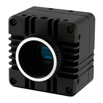
Small Cubic Type
2Meg / 4Meg CMOS Color / Monochrome
Camera Link Camera
STC-CMB2MCL/STC-CMB2MCL-NIR (2Meg, Monochrome)
STC-CMC2MCL (2Meg, Color)
STC-CMB4MCL/STC-CMB4MCL-NIR (4Meg, Monochrome)
STC-CMC4MCL (4Meg, Color)
Product Specifications and Users guide
Sensor Technology Co., Ltd
STC-CMB2MCL/CMC2MCL/CMB4MCL/CMC4MCL
Specifications and Users guide Rev. 2.03
No.13S037-00
1
Advertisement
Table of Contents

Related Manuals for SenTech STC-CMB2MCL


Summary of Contents for SenTech STC-CMB2MCL
- Page 1 No.13S037-00 Small Cubic Type 2Meg / 4Meg CMOS Color / Monochrome Camera Link Camera STC-CMB2MCL/STC-CMB2MCL-NIR (2Meg, Monochrome) STC-CMC2MCL (2Meg, Color) STC-CMB4MCL/STC-CMB4MCL-NIR (4Meg, Monochrome) STC-CMC4MCL (4Meg, Color) Product Specifications and Users guide Sensor Technology Co., Ltd STC-CMB2MCL/CMC2MCL/CMB4MCL/CMC4MCL Specifications and Users guide Rev. 2.03...
- Page 2 Revised the IO information(Input High voltage +5.0V, Output voltage +3.3V) 2.02 2013/05/13 Update Revised 12H[5], Trigger signal input 2.03 2013/06/06 Update Revised Frame rate on page.8,9. 2.04 2013/07/11 Update Added Pixel Defect correction on D8H STC-CMB2MCL/CMC2MCL/CMB4MCL/CMC4MCL Specifications and Users guide Rev. 2.03...
- Page 3 Overview of Binning (2M,4M) ............................ 36 Overview of Subsampling (2M,4M) ........................... 37 4.2.1 Full Scan (STC-CMB2MCL/CMC2MCL) ....................... 38 Table of Video Output on Full Scan mode (STC-CMB2MCL/CMC2MCL).............. 38 4.2.2 Full Scan (STC-CMB4MCL/CMC4MCL) ....................... 39 Table of Video Output on Full Scan mode (STC-CMB4MCL/CMC4MCL).............. 39 4.2.3...
- Page 4 5.2.1 Pulse width trigger mode (V-Reset) ........................ 59 5.2.2 Pulse width trigger mode (Exposure timing) ....................60 The formula ofα1:Exposure time offset (STC-CMB2MCL/CMC2MCL, CMB4MCL/CMC4MCL ....... 60 ............................. 61 DGE PRESET TRIGGER MODE 5.3.1 Edge preset trigger mode (V-Reset) ........................ 61 5.3.2...
- Page 5 ACTUAL CAMERA SETTING & TECHNICAL NOTES ..................85 ........................ 85 SING THE RIGGER IGNAL THROUGH AOI............................86 XAMPLE SETTING OF The value of The horizontal effective pixel, The horizontal effective pixels of changeable DVAL for each setting86 STC-CMB2MCL/CMC2MCL/CMB4MCL/CMC4MCL Specifications and Users guide Rev. 2.03...
-
Page 6: No.13S037
The camera is a general-purpose electronic device; using the camera for the equipment that may threaten human life or cause dangers to human bodies directly in case of failure or malfunction of the camera is not guaranteed. Use the camera for special purposes at your own risk. STC-CMB2MCL/CMC2MCL/CMB4MCL/CMC4MCL Specifications and Users guide Rev. 2.03... -
Page 7: Introduction
No.13S037-00 Introduction This document describes the specifications and users guide of cameras as bellow. STC-CMB2MCL / STC-CMB2MCL-NIR (2M Monochrome / Near IR) STC-CMC2MCL (2M Color) STC-CMB4MCL / STC-CMB4MCL-NIR (4M Monochrome / Near IR) STC-CMC4MCL (4M Color) Features CMOS Sensor(Global Shutter) ... -
Page 8: Specifications
No.13S037-00 Specifications 2.1 Electronic specifications / Mechanical specifications / Environmental specifications 2.1.1 STC-CMB2MCL (2Meg, Monochrome) / STC-CMB2MCL-NIR (2Meg, Near IR) / STC-CMC2MCL (2Meg, Color) Product STC-CMC2MCL STC-CMB2MCL Electro Imager 2/3" Meg color progressive CMOS 2/3" Meg monochrome progressive CMOS (CMOSIS: CMV2000) - Page 9 20Hz to 200Hz to 20Hz (5min./cycle), acceleration 10G, XYZ 3 directions 30 min. each) specific Shock Acceleration 38G, half amplitude 6ms, XYZ 3 directions 3times each ations Standard compliancy EMS: EN61000-6-2, EMI: EN55022 (Class B) RoHS RoHS compliance STC-CMB2MCL/CMC2MCL/CMB4MCL/CMC4MCL Specifications and Users guide Rev. 2.03...
- Page 10 No.13S037-00 2.2 Spectral Sensitivity Characteristics 2.2.1 STC-CMB2MCL / STC-CMB4MCL 2.2.2 STC-CMC2MCL / STC-CMC4MCL STC-CMB2MCL/CMC2MCL/CMB4MCL/CMC4MCL Specifications and Users guide Rev. 2.03...
- Page 11 No.13S037-00 2.2.3 STC-CMB2MCL NIR / STC-CMB4MCL-NIR (Near IR model) Near IR Model Normal Model(Mono) STC-CMB2MCL/CMC2MCL/CMB4MCL/CMC4MCL Specifications and Users guide Rev. 2.03...
-
Page 12: Pin Assignment
D 7 D 6 D 5 D 4 D 3 D 2 D 1 D 0 Xclk- Xclk+ SerTC+ SerTC- SerTFG- SerTFG+ CC1- (TRG) CC1+ (TRG) CC2+ CC2- CC3- CC3+ CC4+ CC4- +12V STC-CMB2MCL/CMC2MCL/CMB4MCL/CMC4MCL Specifications and Users guide Rev. 2.03... - Page 13 Trigger input signal can be assigned either on Camera Link connector (CC1) or on the No. 2 pin of the power/IO connector through the camera setting communication. As for the actual setting of hardware trigger, please refer to 8.1.Using the Trigger Signal through 6pin STC-CMB2MCL/CMC2MCL/CMB4MCL/CMC4MCL Specifications and Users guide Rev. 2.03...
- Page 14 100Ω TC7WH241FK Input Signal Circuit Examples +3.3V +3.3V 6Pin Conector 47kΩ Pin. 2 or 3 or 4 or 5 Camera 2,3,4, Camera input (to FPGA) TC7WH241FK 100Ω Input Voltage 0 to +5.0V DC STC-CMB2MCL/CMC2MCL/CMB4MCL/CMC4MCL Specifications and Users guide Rev. 2.03...
- Page 15 Camera User Output 2,3,4, output Voltage 0 to (from FPGA) +3.3V DC 100Ω TC7WH241FK LED information Mode setting D9H.0 = 1 Trigger mode On 1 second then Off 1 second (repeatedly) Free run STC-CMB2MCL/CMC2MCL/CMB4MCL/CMC4MCL Specifications and Users guide Rev. 2.03...
- Page 16 No.13S037-00 2.5 Dimensions Unit: mm STC-CMB2MCL/CMC2MCL/CMB4MCL/CMC4MCL Specifications and Users guide Rev. 2.03...
- Page 17 No.13S037-00 2.6 Accuracy of Sensor Position Unit:mm STC-CMB2MCL/CMC2MCL/CMB4MCL/CMC4MCL Specifications and Users guide Rev. 2.03...
-
Page 18: Camera Installation
Camera Link Cable x 2 (SDR Connector : Camera side) When using on Full Configuration, please use the cable that has qualification. Frame Graber should support Full, Medium, Base Configuration. When using the PoCL, Frame Graber should support PoCL. STC-CMB2MCL/CMC2MCL/CMB4MCL/CMC4MCL Specifications and Users guide Rev. 2.03... -
Page 19: The Camera Output Timing Charts
No.13S037-00 The camera output timing charts 4.1 The horizontal timings (STC-CMB2MCL/CMC2MCL/CMB4MCL/CMC4MCL) As for the vertical timing, please refer to 4.2.The vertical timings. Highs Speed Clock and Low Speed Clock are existed as Pixel Clock. 4.1.1 2 Taps (1X2-1Y) / Horizontal 2,048 pixels 1 CLK = 11.764 nseconds(85MHz) -
Page 20: Taps (1X4-1Y) / Horizontal 2,048 Pixels
TAP2: DB output pixels ..2022 2026 2030 2034 2038 2042 2046 TAP3: DC output pixels ..2023 2027 2031 2035 2039 2043 2047 TAP4: DD output pixels ..2024 2028 2032 2036 2040 2044 2048 STC-CMB2MCL/CMC2MCL/CMB4MCL/CMC4MCL Specifications and Users guide Rev. 2.03... -
Page 21: Taps (1X8-1Y) / Horizontal 2,048 Pixels
2 CLK 2 CLK 256 CLK Video out (Tap1:DA) Video out (Tap2:DB) Video out (Tap3:DC) Video out (Tap4:DD) Video out (Tap5:DE) Video out (Tap6:DF) Video out (Tap7:DG) Video out (Tap8:DH) Video output Horizontal blanking STC-CMB2MCL/CMC2MCL/CMB4MCL/CMC4MCL Specifications and Users guide Rev. 2.03... - Page 22 TAP6: DF output pixels ..1998 2006 2014 2022 2030 2038 2046 TAP7: DG output pixels ..1999 2007 2015 2023 2031 2039 2047 TAP8: DH output pixels ..2000 2008 2016 2024 2032 2040 2048 STC-CMB2MCL/CMC2MCL/CMB4MCL/CMC4MCL Specifications and Users guide Rev. 2.03...
-
Page 23: Taps (1X10⁻¹Y) / Horizontal 2,040 Pixels
Video out (Tap1:DA) Video out (Tap2:DB) Video out (Tap3:DC) Video out (Tap4:DD) Video out (Tap5:DE) Video out (Tap6:DF) Video out (Tap7:DG) Video out (Tap8:DH) Video out (Tap9:DI) Video out (Tap10:DJ) Horizontal Video output blanking STC-CMB2MCL/CMC2MCL/CMB4MCL/CMC4MCL Specifications and Users guide Rev. 2.03... - Page 24 TAP8: DH output pixels ..1982 1992 2002 2012 2022 2032 2042 TAP9: DG output pixels ..1983 1993 2003 2013 2023 2033 2043 TAP10: DH output pixels ..1984 1994 2004 2014 2024 2034 2044 STC-CMB2MCL/CMC2MCL/CMB4MCL/CMC4MCL Specifications and Users guide Rev. 2.03...
-
Page 25: Taps (1X2-1Y) / Horizontal 1,024 Pixels
1018 1019 1020 1021 1022 1023 1024 1,024 pixels TAP1: DA output pixels ..1011 1013 1015 1017 1019 1021 1023 TAP2: DB output pixels ..1012 1014 1016 1018 1020 1022 1024 STC-CMB2MCL/CMC2MCL/CMB4MCL/CMC4MCL Specifications and Users guide Rev. 2.03... -
Page 26: Taps (1X2-1Y) / Horizontal 512 Pixels
Video out (Tap 1: DA) Video out (Tap 2: DB) Video output Horizontal blanking The pixel order for the Image ..512 pixels TAP1: DA output pixels ..TAP2: DB output pixels ..STC-CMB2MCL/CMC2MCL/CMB4MCL/CMC4MCL Specifications and Users guide Rev. 2.03... -
Page 27: Taps / Horizontal 1,024 Pixels
TAP2: DB output pixels ..1002 1006 1010 1014 1018 1022 TAP3: DC output pixels ..1003 1007 1011 1015 1019 1023 TAP4: DD output pixels ..1000 1004 1008 1012 1016 1020 1024 STC-CMB2MCL/CMC2MCL/CMB4MCL/CMC4MCL Specifications and Users guide Rev. 2.03... -
Page 28: Taps (1X2-1Y) / 2 X 2 Binning
TAP1: DA output pixels 2022 2026 2030 2034 2038 2042 2046 2023+ 2027+ 2031+ 2035+ 2039+ 2043+ 2047+ ..7+8 11+12 15+16 19+20 23+24 27+28 TAP2: DB output pixels 2024 2028 2032 2036 2040 2044 2048 STC-CMB2MCL/CMC2MCL/CMB4MCL/CMC4MCL Specifications and Users guide Rev. 2.03... -
Page 29: Taps (1X4-1Y) / 2 X 2 Binning
TAP2: DB output pixels ..1002 1006 1010 1014 1018 1022 TAP3: DC output pixels ..1003 1007 1011 1015 1019 1023 TAP4: DD output pixels ..1000 1004 1008 1012 1016 1020 1024 STC-CMB2MCL/CMC2MCL/CMB4MCL/CMC4MCL Specifications and Users guide Rev. 2.03... -
Page 30: Taps (1X2-1Y) / 4 X 4 Binning
2046 2047 2048 ・・・ 2041 2042 2043 2044 2045 2046 2047 2048 2041 2042 2043 2044 2045 2046 2047 2048 ・・・ 512 pixels TAP1: DA output pixels ..TAP2: DB output pixels ..STC-CMB2MCL/CMC2MCL/CMB4MCL/CMC4MCL Specifications and Users guide Rev. 2.03... -
Page 31: Taps (1X-1Y) / 8 X 8 Binning
・・・ ・・・ ・・・ ・・・ 2-10 2-16 2033 2034 2040 2041 2042 2048 ・・・ ・・・ 8-10 ・・・ 8-16 ・・・ ・・・ 2033 2034 2040 2041 2042 2048 ・・・ 256 pixels TAP1: DA output pixels ..STC-CMB2MCL/CMC2MCL/CMB4MCL/CMC4MCL Specifications and Users guide Rev. 2.03... -
Page 32: Taps (1X2-1Y)/2 X 2 Subsampling
The pixel order for the Image 1-2045 1-2047 ・・・ 3-2045 3-2047 ・・・ 1024 pixels TAP1: DA output pixels ..1011 1013 1015 1017 1019 1021 1023 TAP2: DB output pixels ..1012 1014 1016 1018 1020 1022 1024 STC-CMB2MCL/CMC2MCL/CMB4MCL/CMC4MCL Specifications and Users guide Rev. 2.03... -
Page 33: Taps (1X4-1Y) / 2 X 2 Subsampling
TAP2: DB output pixels ..1002 1006 1010 1014 1018 1022 TAP3: DC output pixels ..1003 1007 1011 1015 1019 1023 TAP4: DD output pixels ..1000 1004 1008 1012 1016 1020 1024 STC-CMB2MCL/CMC2MCL/CMB4MCL/CMC4MCL Specifications and Users guide Rev. 2.03... -
Page 34: Taps (1X2-1Y) / 4 X 4 Subsampling
(Tap1: DA) Video out (Tap2: DB) Video output Horizontal blanking The pixel order for the Image 1-2041 1-2045 ・・・ 5-2041 5-2045 ・・・ 512 pixels TAP1: DA output pixels ..TAP2: DB output pixels ..STC-CMB2MCL/CMC2MCL/CMB4MCL/CMC4MCL Specifications and Users guide Rev. 2.03... -
Page 35: Taps (1X-1Y)/8 X 8 Subsampling
2 CLK 2 CLK 256 CLK Video out (Tap1: DA) Video output Horizontal blanking The pixel order for the Image 1-2033 1-2041 ・・・ 9-2033 9-2041 ・・・ 256 pixels TAP1: DA output pixels ..STC-CMB2MCL/CMC2MCL/CMB4MCL/CMC4MCL Specifications and Users guide Rev. 2.03... -
Page 36: T He V Ertical Timings
All of the lines and pixels are output and the entire image is shown. For transmitting the image, some configurations will not be supported, or can drop the frame rate.. Output image from Sensor on Fullscan (STC-CMB2MCL/CMC2MCL) Output image from Sensor on Fullscan (STC-CMB4MCL/CMC4MCL) Overview of Binning (2M,4M) The average pixel value is output and shown in the image. -
Page 37: Overview Of Subsampling (2M,4M)
FOV (Field of View). Output image from Sensor on 2 x2 subsampling Output image from Sensor on 4 x4subsampling Output image from Sensor on 8 x 8 subsampling STC-CMB2MCL/CMC2MCL/CMB4MCL/CMC4MCL Specifications and Users guide Rev. 2.03... -
Page 38: Full Scan (Stc-Cmb2Mcl/Cmc2Mcl)
4.2.1 Full Scan (STC-CMB2MCL/CMC2MCL) 1116 H One vertical (1V) FVAL 1088 H 28 H Video out Vertical blanking Video output Table of Video Output on Full Scan mode (STC-CMB2MCL/CMC2MCL) Mode Configuration CameraLink Output Horizontal Pixel Sensor Output Pixel Camera Link (29H) Number... -
Page 39: Full Scan (Stc-Cmb4Mcl/Cmc4Mcl)
8/10 Base 42.5 1024 10.625 39.7 8/10 Base 42.5 21.250 79.3 8/10 Medium 42.5 2048 10.625 39.7 8/10 Medium 42.5 1024 21.250 79.3 8/10 Full 42.5 2048 21.250 79.3 40.0 2040 24.000 89.6 STC-CMB2MCL/CMC2MCL/CMB4MCL/CMC4MCL Specifications and Users guide Rev. 2.03... -
Page 40: X 2 Binning (Stc-Cmb2Mcl/Cmc2Mcl)
No.13S037-00 4.2.3 2 x 2 Binning (STC-CMB2MCL/CMC2MCL) 558 H One vertical (1V) FVAL 14 H 544 H Video out Vertical Video output blanking 4.2.4 4 x 4 Binning (STC-CMB2MCL/CMC2MCL) 279 H One vertical (1V) FVAL 272 H Video out Vertical... -
Page 41: Table Of Video Output On Binning Mode (Stc-Cmb2Mcl/Cmc2Mcl)
No.13S037-00 Table of Video Output on Binning mode (STC-CMB2MCL/CMC2MCL) Averaged the pixels data is used for Binning mode. It makes decreasing the noise level and increasing the Signal Noise Ratio. This camera has row and column binning modes. This mode can not increase the frame rate. -
Page 42: X 2 Subsampling (Stc-Cmb2Mcl/Cmc2Mcl)
No.13S037-00 4.2.6 2 x 2 Subsampling (STC-CMB2MCL/CMC2MCL) 566 H One vertical (1V) FVAL 28 H 544 H Video out Vertical blanking Video output 4.2.7 4 x 4 Subsampling (STC-CMB2MCL/CMC2MCL) 296 H One vertical (1V) FVAL 28 H 274 H 28 H... -
Page 43: Table Of Video Output On Subsampling Mode (Stc-Cmb2Mcl/Cmc2Mcl)
No.13S037-00 Table of Video Output on Subsampling mode (STC-CMB2MCL/CMC2MCL) Subsampling reduce the output resolution and increase the frame rate.without FOV(Field of View). This camera has row and column subsampling modes. This mode can not reduce the noise level. Mode Binning... -
Page 44: X 2 Binning (Stc-Cmb4Mcl/Cmc4Mcl)
FVAL 572 H Video out Vertical Video output blanking 4.2.11 8 x 8 Binning (STC-CMB4MCL/CMC4MCL) 259.5 H One vertical (1V) FVAL 3.5 H 256 H 3.5 H Video out Vertical Video output blanking STC-CMB2MCL/CMC2MCL/CMB4MCL/CMC4MCL Specifications and Users guide Rev. 2.03... -
Page 45: Table Of Video Output On Binning Mode (Stc-Cmb4Mcl/Cmc4Mcl)
2 x 2 Base 42.5 1024 10.625 39.7 8/10/12 4 x 4 Base 42.5 21.250 79.3 8/10/12 2 x 2 Medium 42.5 1024 21.250 79.3 8/10/12 8 x 8 Base 42.5 21.250 79.3 8/10/12 STC-CMB2MCL/CMC2MCL/CMB4MCL/CMC4MCL Specifications and Users guide Rev. 2.03... -
Page 46: X 2 Subsampling (Stc-Cmb4Mcl/Cmc4Mcl)
512 H 28 H Video out Vertical blanking Video output 4.2.14 8 x 8 Subsampling (STC-CMB4MCL/CMC4MCL) 284 H One vertical (1V) FVAL 28 H 256 H 28 H Video out Vertical blanking Video output STC-CMB2MCL/CMC2MCL/CMB4MCL/CMC4MCL Specifications and Users guide Rev. 2.03... -
Page 47: Table Of Video Output On Subsampling Mode(Stc-Cmb4Mcl/Cmc4Mcl)
2 x 2 Base 42.5 1024 10.625 78.3 8/10 4 x 4 Base 42.5 21.250 305.1 8/10 2 x 2 Medium 42.5 1024 21.250 156.6 8/10 8 x 8 Base 42.5 21.250 580.0 8/10 STC-CMB2MCL/CMC2MCL/CMB4MCL/CMC4MCL Specifications and Users guide Rev. 2.03... -
Page 48: Aoi Output Timing
Register[4EH,4FH2-0]=H_NUMBER: Horizontal available pixel number ÷ Output TAP number ÷ Binning or Subsampling number When use the 10 TAP, horizontal pixel number is 2040 pixel. using H_STRAT: Horizontal start position -4. Register[4EH,4FH2-0]=(H_NUMBER: Horizontal available pixel number -4 )÷ Output TAP number ÷ Binning or Subsampling number STC-CMB2MCL/CMC2MCL/CMB4MCL/CMC4MCL Specifications and Users guide Rev. 2.03... - Page 49 No.13S037-00 H-TOTAL LVAL 4C-4Dh 4E-4Fh AOI_1 AOI_2 AOI_3 V-BLK STC-CMB2MCL/CMC2MCL/CMB4MCL/CMC4MCL Specifications and Users guide Rev. 2.03...
- Page 50 Register[4EH,4FH2-0] =H_NUMBER: Horizontal available pixel number ÷ Output TAP number ÷ Binning or Subsampling number = 640 ÷ 8 ÷ 1 = 80 As for the actual setting of AOI, please refer to the 8.2Example setting of AOI. STC-CMB2MCL/CMC2MCL/CMB4MCL/CMC4MCL Specifications and Users guide Rev. 2.03...
-
Page 51: C Amera L Ink Bit Assignment
XCLK DVAL FVAL LVAL DA1 DA0 DA8 DA5 DA4 DA3 DA2 DA1 DA0 DA0 to DA9: 10bit data for one pixel from TAP1 DB0 to DB9: 10bit data for one pixel from TAP2 STC-CMB2MCL/CMC2MCL/CMB4MCL/CMC4MCL Specifications and Users guide Rev. 2.03... - Page 52 DC0 to DC7: 8bit data for one pixel from TAP3 DC0 to DC9: 10bit data for one pixel from TAP3 DD0 to DD7: 8bit data for one pixel from TAP4 DD0 to DD9: 10bit data for one pixel from TAP4 STC-CMB2MCL/CMC2MCL/CMB4MCL/CMC4MCL Specifications and Users guide Rev. 2.03...
- Page 53 8bit data for one pixel from TAP5 DF0 to DF7: 8bit data for one pixel from TAP6 DG0 to DG7: 8bit data for one pixel from TAP7 DH0 to DH7: 8bit data for one pixel from TAP8 STC-CMB2MCL/CMC2MCL/CMB4MCL/CMC4MCL Specifications and Users guide Rev. 2.03...
- Page 54 8bit data for one pixel from TAP7 DH0 to DH7: 8bit data for one pixel from TAP8 DI0 to DI7: 8bit data for one pixel from TAP9 DJ0 to DJ7: 8bit data for one pixel from TAP10 STC-CMB2MCL/CMC2MCL/CMB4MCL/CMC4MCL Specifications and Users guide Rev. 2.03...
-
Page 55: Tap (1X4-1Y)
No.13S037-00 Camera Link TAP Geometry 4.5.1 2TAP (1X2-1Y) Sep X = 2 Tap2 Tap1 4.5.2 4TAP (1X4-1Y) Sep X = 4 Tap1 Tap2 Tap3 Tap4 STC-CMB2MCL/CMC2MCL/CMB4MCL/CMC4MCL Specifications and Users guide Rev. 2.03... -
Page 56: Tap (1X8-1Y)
No.13S037-00 4.5.3 8TAP (1X8-1Y) Sep X = 8 Tap1 Tap2 Tap3 Tap4 Tap5 Tap6 Tap7 Tap8 4.5.4 10TAP (1X10⁻¹Y) Sep X =10 Tap1 Tap2 Tap3 Tap4 Tap5 Tap6 Tap7 Tap8 Tap9 Tap10 STC-CMB2MCL/CMC2MCL/CMB4MCL/CMC4MCL Specifications and Users guide Rev. 2.03... -
Page 57: B Ayer Pattern For Color Model (O Nly Stc-Cmc2Mcl / Stc-Cmc4Mcl)
No.13S037-00 Bayer pattern for color model (Only STC-CMC2MCL / STC-CMC4MCL) STC-CMB2MCL/CMC2MCL/CMB4MCL/CMC4MCL Specifications and Users guide Rev. 2.03... -
Page 58: Camera Function Modes
I n t e r n a l V D E x p o s u r e t i m e C C D e x p o s u r e V i d e o o u t STC-CMB2MCL/CMC2MCL/CMB4MCL/CMC4MCL Specifications and Users guide Rev. 2.03... - Page 59 5.2.1 Pulse width trigger mode (V-Reset) Trigger signal (Positive) Internal VD *Note. 1 Exposure exposure time Video out FVAL Note.1: The exposure time sets by the pulse width of the trigger signal. STC-CMB2MCL/CMC2MCL/CMB4MCL/CMC4MCL Specifications and Users guide Rev. 2.03...
-
Page 60: Pulse Width Trigger Mode (Exposure Timing)
Please input the trigger signal has more than 1.5 us pulse width. Note.2: α1(Exposure time offset) is different from using clock, TAP number. The formula ofα1:Exposure time offset (STC-CMB2MCL/CMC2MCL, CMB4MCL/CMC4MCL α1 = 129 / Sensor Output Pixel Clock x 20 x 0.43... - Page 61 Exposure duration time is preset by the “Electrical Shutter” settings. 5.3.1 Edge preset trigger mode (V-Reset) Trigger signal (Rising edge) Internal VD *Note. 1 Exposure exposure time Video out FVAL Note.1: The exposure time sets by the preset electronic shutter speed. STC-CMB2MCL/CMC2MCL/CMB4MCL/CMC4MCL Specifications and Users guide Rev. 2.03...
-
Page 62: Edge Preset Trigger Mode (Exposure Timing)
Please input the trigger signal has more than 1.5 us pulse width. Note.2: α1(Exposure time offset) is different from using clock, TAP number. The formula ofα1:Exposure time offset (STC-CMB2MCL/CMC2MCL, CMB4MCL/CMC4MCL α1 = 129 / Sensor Output Pixel Clock x 20 x 0.43... -
Page 63: The Communication Protocol Specifications
4. About for one second after switching frame rate. 6.1 The communication method UART (RS232C), Binary communication 6.2 The communication settings Settings Baud rate 9,600bps / 38,400bps /57,600bps / 115,200bps Data bit 8bit Parity None Stop bit 1bit Flow control None STC-CMB2MCL/CMC2MCL/CMB4MCL/CMC4MCL Specifications and Users guide Rev. 2.03... -
Page 64: T He Communication Format
The value of the data is depending on the command End of the frame Sets (or gets) the value is as “03H” always Receiving code Result of the sending command 01H: OK (ACK), 10H: Receiving problem (NAC), 11H: Communication problem STC-CMB2MCL/CMC2MCL/CMB4MCL/CMC4MCL Specifications and Users guide Rev. 2.03... - Page 65 Send the read command to read the 00H address data of the register 02, 00, 00, 01, 00, 03 SOF, (Device code/Read/Register), Command code, Data length, Data, EOF The return command 02, 01, 00, 03 STC-CMB2MCL/CMC2MCL/CMB4MCL/CMC4MCL Specifications and Users guide Rev. 2.03...
-
Page 66: The Camera Control Commands
The effective lines of the variable partial scanning D (16bit: D[15..8]) CMB/CMC4MCL: 0 CMB/CMC4MCL: 0 to 2,048 44 to 46H Reserved Read / Write HDR slope (8bit: D[7..0]) 48 to 4AH Reserved Read / Write PGA (8bit: D[7..0]) STC-CMB2MCL/CMC2MCL/CMB4MCL/CMC4MCL Specifications and Users guide Rev. 2.03... - Page 67 The effective lines of the variable partial scanning H (16bit: D[15..8]) CMB/CMC4MCL: 0 CMB/CMC4MCL: 0 to 2,048 9Cto D7H Reserved Read / Write Pixel Defect Read / Write LED control (8bit: D[7..0]) DAto FFH Reserved STC-CMB2MCL/CMC2MCL/CMB4MCL/CMC4MCL Specifications and Users guide Rev. 2.03...
- Page 68 D1 to D0: Communication mode 00: 38,400bps, 01: 9,600bps 10: 57,600bps, 11: 115,200bps *Note 12H:Video out bit can be selected by mode. As for the support mode, please refer to 4.2The Vertical timings. STC-CMB2MCL/CMC2MCL/CMB4MCL/CMC4MCL Specifications and Users guide Rev. 2.03...
- Page 69 No.13S037-00 Command descriptions Command No. 15H: [The start line of the variable partial scanning B] STC-CMB2MCL/CMC2MCL: Initial data: PSRB[15..0] = 0, data range: 0 to 1,087 PSRB[7..0] 16H: STC-CMB4MCL/CMC4MCL: Initial data: PSRB[15..0] = 0, data range: 0 to 2,047 PSRB[15..8] Sets the start line of the variable partial scanning B.
- Page 70 When set 0 for SVR[23..0], the camera works with 2,048 line exposure. 24H: [The start line of the variable partial scanning] PSR[7..0] STC-CMB2MCL/CMC2MCL: Initial data: PSR[15..0] = 0, data range: 0 to 1,087 25H: STC-CMB4MCL/CMC4MCL: Initial data: PSR[15..0] = 0, data range: 0 to 2,047 PSR[15..8] Sets the start line of the variable partial scanning.
- Page 71 No function Sets always as "0" D2 to D0: Output taps and frame rate (STC-CMB2MCL/CMC2MCL/STC-CMB4MCL/CMC4MCL) 0 : 2TAP (85.0MHz, Horizontal: 2,048 pixels), 1 : 4TAP (85.0MHz, Horizontal: 2,048 pixels), 2 : 8TAP (85.0MHz, Horizontal: 2,048 pixels), 3 : 10TAP (80.0MHz, Horizontal: 2,048 pixels), 4 : Reserved 5 : 2TAP (85.0MHz, Horizontal: 1,024 pixels),...
- Page 72 No.13S037-00 Command descriptions Command No. 40H: [The start line of the variable partial scanning D] STC-CMB2MCL/CMC2MCL: Initial data: PSRD[15..0] = 0, data range: 0 to 1,087 PSRD[7..0] 41H: STC-CMB4MCL/CMC4MCL: Initial data: PSRD[15..0] = 0, data range: 0 to 2,047 PSRD[15..8] Sets the start line of the variable partial scanning D.
- Page 73 The horizontal effective pixels sets as number of horizontal pixels automatically. When the horizontal effective pixels is 0, The horizontal start position sets as 0 automatically. The horizontal effective pixels sets as number of horizontal pixels automatically. STC-CMB2MCL/CMC2MCL/CMB4MCL/CMC4MCL Specifications and Users guide Rev. 2.03...
- Page 74 No.13S037-00 Command descriptions Command No. 50H: [The start line of the variable partial scanning E] STC-CMB2MCL/CMC2MCL: Initial data: PSRE[15..0] = 0, data range: 0 to 1,087 PSRE[7..0] 51H: STC-CMB4MCL/CMC4MCL: Initial data: PSRE[15..0] = 0, data range: 0 to 2,047 PSRE[15..8] Sets the start line of the variable partial scanning E.
- Page 75 03H: 7bit gradation, 04H: 6bit gradation, 05H: 5bit gradation, 06H: 4bit gradation, 07H: 3bit gradation, 08H: 2bit gradation, 09H: 1bit gradation, 0A to 7FH: No function (Prohibited setting. Do not set these values) STC-CMB2MCL/CMC2MCL/CMB4MCL/CMC4MCL Specifications and Users guide Rev. 2.03...
- Page 76 No.13S037-00 Command descriptions Command No. 90H: [The start line of the variable partial scanning F] STC-CMB2MCL/CMC2MCL: Initial data: PSRF[15..0] = 0, data range: 0 to 1,087 PSRF[7..0] 91H: STC-CMB4MCL/CMC4MCL: Initial data: PSRF[15..0] = 0, data range: 0 to 2,047 PSRF[15..8] Sets the start line of the variable partial scanning F.
- Page 77 Command No. 98H: [The start line of the variable partial scanning H] PSRH[7..0] STC-CMB2MCL/CMC2MCL: Initial data: PSRH[15..0] = 0, data range: 0 to 1,087 99H: STC-CMB4MCL/CMC4MCL: Initial data: PSRH[15..0] = 0, data range: 0 to 2,047 PSRH[15..8] Sets the start line of the variable partial scanning H.
-
Page 78: Sequence For The Command Saves To The Eeprom
Note.3) When save the multiple command data, which is not sequence command, to the EEPROM, it is necessary to operate the number of times from 1) to 4). Example of the multiple command: “10H, 13H, 19H and 1BH” or “20H, 23H and 25H”. STC-CMB2MCL/CMC2MCL/CMB4MCL/CMC4MCL Specifications and Users guide Rev. 2.03... -
Page 79: Control Software
Save the camera setting data on the register to EEPROM. As for the detail, please refer to the next chapter Comm. Read the camera setting data from Register. As for the detail, please refer to the next chapter Comm. STC-CMB2MCL/CMC2MCL/CMB4MCL/CMC4MCL Specifications and Users guide Rev. 2.03... -
Page 80: Open[From File To Register]
Save the register data into the EEPROM on the camera. When camera turns off, data remain on the EEPROM. EEPROM -> Register Read the EEPROM data into the register. When saved data wants to be used again, this can be done. STC-CMB2MCL/CMC2MCL/CMB4MCL/CMC4MCL Specifications and Users guide Rev. 2.03... -
Page 81: Factory -> Eeprom
Effectrical shutter setting can be set through the slide ba or set through the actrual register value. Actual exposure time appears on the bottom of the slide bar. As for the detail of exposure time setting, please refer to the6.The communication protocol specifications. STC-CMB2MCL/CMC2MCL/CMB4MCL/CMC4MCL Specifications and Users guide Rev. 2.03... -
Page 82: Mode
Video output bit can be selected from 8/10/12 bit. Video output bit is different for each mode. As for the relation of mode to video output, please refer to the 4.2.The Vertical timings. 7.2.3 Gain STC-CMB2MCL/CMC2MCL/CMB4MCL/CMC4MCL Specifications and Users guide Rev. 2.03... -
Page 83: Digital Gain
CameraLink Output PixelClock Frequency(MHz) support High speed mode and Low speed mode. Clock speed can be selected by frame rate, Camera Link Output Bit and Video mode. As for the detail, please refer to the 4.2.The Vertical timings. STC-CMB2MCL/CMC2MCL/CMB4MCL/CMC4MCL Specifications and Users guide Rev. 2.03... -
Page 84: S Oftware F Unction (Hdr)
This tab uses for the power user to control the Gamma deeply. Do not use the color model. 7.6 Software Function (SP Pin) External trigger can be used. As for the detail, please refer to the 8.1. Using the Trigger Signal through 6pin. STC-CMB2MCL/CMC2MCL/CMB4MCL/CMC4MCL Specifications and Users guide Rev. 2.03... -
Page 85: Actual Camera Setting & Technical Notes
3. Input the trigger signal through Pin2. As for using the software, please refer to the 6.Control Software. SP Pin Signal Selection Table Pin No Addr=F0 AfterTrigger FILTER LVAL FVAL Trigger Input F1h.0 F1h.1 F1h.2 F1h.3 T_EXP1 FRAME_REQ HIGH in Exposure T_EXP1 FRAME_REQ FVAL 4 ~15 Reserved STC-CMB2MCL/CMC2MCL/CMB4MCL/CMC4MCL Specifications and Users guide Rev. 2.03... -
Page 86: E Xample Setting Of Aoi
Register[4EH,4FH2-0] =640 ÷ TAP Number ÷ Binning or Subsampling number = 640 ÷ 8 ÷ 1 = 80 The horizontal Binning or Subsampling Horizontal The horizontal effective pixels of Mode(29H) changeable DVAL TAP Number number Pixel effective pixel 2048 Progressive 2048 Progressive 2048 Progressive 2040 Progressive 1024 Progressive Progressive STC-CMB2MCL/CMC2MCL/CMB4MCL/CMC4MCL Specifications and Users guide Rev. 2.03... - Page 87 8x8 Subsampling *Note :Horizontal pixel is 2040 on 10 TAP mode, then formula of “The horizontal effective pixel” is different. The horizontal effective pixel Register[4CH,4DH2-0] =(Horizontal start position -4) ÷ 10 TAP ÷ 1 STC-CMB2MCL/CMC2MCL/CMB4MCL/CMC4MCL Specifications and Users guide Rev. 2.03...
- Page 88 No.13S037-00 7F, Harada center building 9-17, Naka cho 4 chome Atsugi-city, Kanagawa 243-0018 Japan Sensor Technology Co., Ltd TEL 81-46-295-7061 FAX 81-46-295-7066 URL http://www.sentech.co.jp/ STC-CMB2MCL/CMC2MCL/CMB4MCL/CMC4MCL Specifications and Users guide Rev. 2.03...
Need help?
Do you have a question about the STC-CMB2MCL and is the answer not in the manual?
Questions and answers