Table of Contents
Advertisement
Quick Links
ReAL-TIMe STeeRINg ARRAy MICROphONeS
Thank you for purchasing TOA's Real-Time Steering Array Microphone.
Please carefully follow the instructions in this manual to ensure long, trouble-free use of your equipment.
English :
page 1
中文 (簡体字) : 第 27 页
中文 (繁体字) : 第 51 頁
日本語 :
INSTRUCTION MANUAL
AM-1B
AM-1W
75 ページ
Advertisement
Table of Contents

Related Manuals for Toa AM-1B


Summary of Contents for Toa AM-1B
- Page 1 中文 (簡体字) : 第 27 页 日本語 : 75 ページ INSTRUCTION MANUAL ReAL-TIMe STeeRINg ARRAy MICROphONeS AM-1B AM-1W Thank you for purchasing TOA’s Real-Time Steering Array Microphone. Please carefully follow the instructions in this manual to ensure long, trouble-free use of your equipment.
- Page 2 TABLe OF CONTeNTS 1. SAFeTy pReCAUTIONS ................3 2. ABOUT INSTRUCTION MANUALS ............4 3. geNeRAL DeSCRIpTION ................5 4. FeATUReS ......................5 5. hANDLINg pReCAUTIONS ..............5 6. NOMeNCLATURe AND FUNCTIONS ..........6 6.1. Array Microphone ....................6 6.2. Control Unit ......................7 7.
-
Page 3: Safety Precautions
• Use the specified rack mounting bracket in combination. Doing otherwise may cause the unit or component to fall off, resulting in personal injury. When the Unit is in Use • Should the following irregularity be found during use, immediately switch off the power, disconnect the power supply plug from the AC outlet and contact your nearest TOA dealer. Make no further attempt to operate the unit in this condition as this may cause fire or electric shock. · If you detect smoke or a strange smell coming from the unit. · If water or any metallic object gets into the unit · If the unit falls, or the unit case breaks... -
Page 4: About Instruction Manuals
· Install the equipment rack on a stable, hard floor. Fix it with anchor bolts or take other arrangements to prevent it from falling down. · When connecting the AC adapter’s power cord to an AC outlet, use the AC outlet with current capacity allowable to the unit. · The supplied rack-mounting screws can be used for the TOA equipment rack only. Do not use them for other racks. When the Unit is in Use • Use the specified AC adapter for the unit. Note that the use of other adapter may cause a fire. -
Page 5: General Description
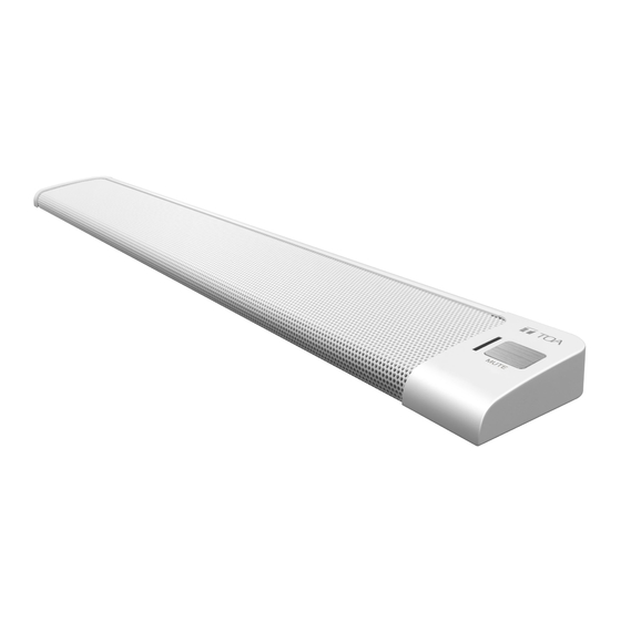
The AM Series is a Real-time Steering Array Microphone that efficiently picks up targeted sound by using a unique algorithm to detect the position of the sound source and control the microphone’s directivity. This microphone system consists of an array microphone unit and its control unit. The array microphone is available in two different versions: AM-1B (black) and AM-1W (white). 4. FeATUReS • The array microphone utilizes eight microphone elements to realize an array effect by means of its narrow 50° horizontal angle of directivity. -
Page 6: Nomenclature And Functions
6. NOMeNCLATURe AND FUNCTIONS 6.1. Array Microphone [Top] MUTE 1. Microphone section 3. Microphone status indicator (green/red) Eight microphone elements are housed within the Indicates the microphone status when the array main body of the microphone. microphone is connected to the control unit. Note Power OFF: Unlit... -
Page 7: Control Unit
Connect this terminal to the audio input terminal 8. power input terminal of a mixer or amplifier. Connects to the optional AD-246 AC Adapter or the equivalent. As for the usable adapter, consult your 13. Output level selection switch TOA dealer. Switches the audio output level. Switchover levels: −50 dB* / −10 dB* / +4 dB* 9. Network connection terminal (RJ45 jack) Connects to a 10BASE-T or 100BASE-TX compati- 14. -
Page 8: Connection
7.2. Connecting the AC adapter Connect the AC adapter* to the control unit’s power input terminal. Secure the cord with clamp. Use the optional AC adapter AD-246 or equivalent. For alternate adapters, consult your TOA dealer. AC adapter AD-246 (option) Cord clamp CAUTION SIGNAL For AC adapters, use TOA optional AD- DC INPUT 410mA 246 Adapter . The use of or the equivalent other adapters could result in fire or other possible damage. -
Page 9: Network Connections
7.3. Network Connections The control unit automatically distinguishes between 10BASE-T and 100BASE-TX networks and establishes a connection. For this connection, use a straight UTP Category 5 or greater LAN (Ethernet) cable terminated with an RJ45 connector. Control unit SIGNAL DC INPUT 410mA -10dBV -50dBu +4dBu OFF ON MIC INPUT OUTPUT OUTPUT LEVEL LOW-CUT To switching hub 7.4. -
Page 10: Installing The Control Unit
8. INSTALLINg The CONTROL UNIT 8.1. Rack Mounting • Use the optional mounting hardware set when installing the unit in an equipment rack. • Remove four rubber feet mounted on the bottom of the unit before mounting in a rack. 8.1.1. When mounting a single unit Use the optional MB-15B-BK hardware set when mounting a single unit. 3 x 14 tapping screw * Component parts of MB-15B-BK 3 x 8 tapping screw * Control unit Blank bracket * 3 x 8 tapping screw *... -
Page 11: Wall Mounting
8.2. Wall Mounting Use the optional YC-850 hardware set when mounting the unit on a wall. Step 1. Install the optional YC-850 Wall Mounting Bracket to the control unit. YC-850 Wall mounting bracket (Option) M3 x 6 machine screw (supplied with the YC-850) Step 2. Mount the control unit on the wall. Notes • Use appropriate screws when mounting to a wall. -
Page 12: Equipment Settings
9. eQUIpMeNT SeTTINgS 9.1. Audio Output Selection Step 1. Confirm that all equipment cables and connectors are correctly connected. Step 2. Set the output level selection switch to an appropriate position in accordance with the level of the connected mixer, amplifier etc. Control unit [Output Level Selection switch] -10dBV -50dBu +4dBu SIGNAL DC INPUT 410mA -10dBV... -
Page 13: System Settings
10. SySTeM SeTTINgS 10.1. System Settings Summary By installing the dedicated AM-1 iOS app on an iPad, the following function settings, real-time monitoring and control can be performed: Function settings and control can also be performed by may of a PC web browser. [Real-Time Monitoring] • Check of sound source position and input audio level. • Check of audio input level of individual microphone elements. [Function Settings] • Tracking range setting: Horizontal angle and distance • Detection sensitivity • Tracking speed • Sound volume correction: Function ON/OFF and effective distance settings • Mute switch function ON/OFF • Saving setting configuration [Control] • Output volume level adjustment... -
Page 14: Ipad ® Settings
10.3. ipad Settings ® 10.3.1. Summary To perform settings using an iPad, install the AM-1 iOS app on the iPad. The AM-1 app is a dedicated program created for the iPad which can be downloaded from the App Store for free of cost. It connects to the AM-1 control unit via a wireless network, allowing settings, control, and monitoring of the array microphone. 10.3.2. - Page 15 After installation is completed, the "TOA AM-1" icon will appear on the iPad’s home screen. 10.3.3. Starting preparations Perform Wi-Fi setup using the iPad’s settings controls. Confirm that the iPad’s IP address and the control unit’s IP address are set to the same network. Notes • The control unit’s factory-preset IP address is 192.168.1.14. • For more information on use of the AM-1 iOS app, please refer to the "Software Instruction Manual" supplied separately.
-
Page 16: Settings Using Web Browser
10.4. Settings Using Web Browser 10.4.1. Summary Many functions of the array microphone and control unit can be set using a PC web browser. 10.4.2. Menu screen Start the web browser and enter the control unit’s IP address* in the browser’s address field to display the menu screen. Factory-preset to 192.168.1.14. Network Setting: Network settings Mic Settings 1: Microphone settings 1 Mic Settings 2: Microphone settings 2 Settings Load/Save: Loading or saving of settings... - Page 17 10.4.3. Network settings Click "Network Setting" on the menu screen. Set the control unit’s network settings. The following items can be edited: IP Address: Enter the IP address. Subnet Mask: Enter the subnet mask. Default Gateway: Enter the default gateway. MAC Address: The MAC address cannot be changed. ArrayMic Name: Enter the array microphone name (Up to 16 alphanumeric characters and symbols). [Button Operation] Save: Saves the set contents to the built-in memory "Default." Note After changing the network settings, turn OFF the control unit’s power, then turn it back ON again. After the control unit is restarted, open this screen and confirm that the settings have been correctly changed.
- Page 18 10.4.4. Microphone settings 1 Click "Mic Settings 1" on the menu screen. Perform microphone parameter settings related to Tracking Control. [Tracking Control selection] Select either ON or OFF mode with the radio button. Performs automatic tracking. OFF: Does not perform automatic tracking. [Microphone settings when Tracking Control is set to ON] The horizontal angle range ( − 90 to + 90 [deg]) for carrying out automatic tracking. Tracking Angle: Tracking Distance: T he distance (0.5 to 3.0 or ∞ [m]) for carrying out automatic tracking. Note: Figures larger than 3.1 [m] are treated as ∞ and displayed as "15.0 [m]." Tracking Speed: Sets the speed at which the microphone tracks the sound source. The larger the number, the faster the tracking speed (1 to 100).
- Page 19 10.4.5. Microphone settings 2 Click "Mic Settings 2" on the menu screen. Set microphone parameters other than Tracking Control. Output Mode: Select either Array mode or Cardioid mode. Array mode: D etects the sound source position and causes the microphone to function as an array microphone that performs signal processing to maintain a constant sound volume.
- Page 20 10.4.6. Loading or saving the set contents Click "Setting Load/Save" on the menu screen. Load or save settings. Load: Reads the settings saved to the built-in memory. Select the reading source from "Default," "Preset 1," and "Preset 2." Save: S aves settings to the built-in memory. Select the save destination of "Default," "Preset 1," or "Preset 2." Note: The setting loaded or saved last is read when the control unit’s power is turned ON again. [Button Operation] Reads settings from the place selected with the radio button or saves settings to the place selected with the radio button.
-
Page 21: Starting The System In Test Mode
11. STARTINg The SySTeM IN TeST MODe WARNINg Leave the work described here to the professionals. Fire or electrical shock could result from the customer opening the case or modifying the unit. When the IP address is unknown, it can be restored to factory-preset status by starting the system in Test mode. Follow the procedures below to start in Test mode: Notes • Ensure that the control unit’s power is turned OFF when doing this work. • Do not touch any parts or components on the circuit board. Static electricity could cause the control unit to fail. • All previously saved network settings are placed in factory-preset status. Step 1. Remove the 4 screws that hold the control unit’s top panel to remove the top panel. Top panel Control unit Circuit board... - Page 22 Step 2. Shift DIP switch 1 on the circuit board to the ON position and turn ON the control unit’s power. The RUN indicator flashes green as shown below: Circuit board Front side Rear side [Close-up view of the DIP switch] [Close-up view of RUN indicator] Flashes green. Circuit: D811 Set DIP Switch 1 to ON. Step 3. After confirming that the RUN indicator is flashing green, turn OFF the control unit’s power. Step 4. Shift DIP Switch 1 back to the OFF position. Step 5. Reattach the top panel as before. Reverts to the factory-preset network setting.
-
Page 23: Troubleshooting
Check the input level meter using the iOS app of order. to confirm that all of the array microphone’s 8 microphone elements are operating normally. Contact your nearest TOA dealer if any micro- phone elements are not operating correctly. Does not automatically Tracking settings are not Confirm that Tracking Control is set to ON. -
Page 24: Specifications
13. SpeCIFICATIONS Model No. AM-1B AM-1W Product Composition Array microphone ... 1, Control unit ... 1 Array Microphone Power Source 24 V DC (supplied from the Control unit) Microphone Unidirectional electret condenser microphone Directivity Angle Horizontal: 50º (800 Hz – 18 kHz, Array mode), 180º (Cardioid mode) Vertical: 90º Frequency Response 150 Hz – 18 kHz Maximum Input Sound 100 dB SPL Pressure Operation Mute switch... -
Page 25: Accessory
• Accessory Removable terminal plug (3 pins) ... 1 • Optional products AC adapter: AD-246* Rack mounting bracket: MB-15B-BK (for rack mounting one control unit) MB-15B-J (for rack mounting two control units) Wall mounting bracket: YC-850 (for one control unit) * Consult your TOA dealer when using an equivalent adapter. - Page 26 Traceability Information for europe Manufacturer: Authorized representative: TOA Corporation TOA Electronics Europe GmbH 7-2-1, Minatojima-Nakamachi, Chuo-ku, Kobe, Hyogo, Suederstrasse 282, 20537 Hamburg, Japan Germany URL: http://www.toa.jp/...
Need help?
Do you have a question about the AM-1B and is the answer not in the manual?
Questions and answers