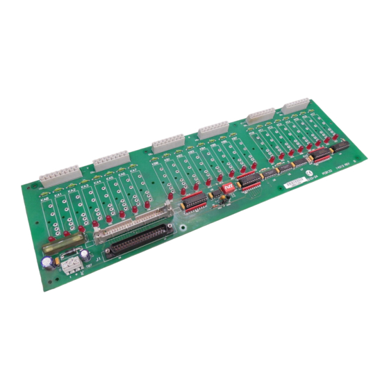
Summary of Contents for Keithley SSIO-24
- Page 1 SSIO-24 Digital I/O Board User Guide A G R E A T E R M E A S U R E O F C O N F I D E N C E...
- Page 2 WARRANTY Hardware Keithley Instruments, Inc. warrants that, for a period of one (1) year from the date of ship- ment (3 years for Models 2000, 2001, 2002, 2010 and 2700), the Keithley Hardware prod- uct will be free from defects in materials or workmanship. This warranty will be honored provided the defect has not been caused by use of the Keithley Hardware not in accor- dance with the instructions for the product.
- Page 3 Other Items Keithley warrants the following items for 90 days from the date of shipment: probes, cables, rechargeable batteries, diskettes, and documentation. Items not Covered under Warranty This warranty does not apply to fuses, non-rechargeable batteries, damage from battery leak- age, or problems arising from normal wear or failure to follow instructions.
- Page 4 User Guide for the SSIO-24 Digital I/O Board Revision C – August 2002 Copyright © Keithley Data Acquisition 1991 Part Number: 81250 Keithley Instruments, Inc. 28775 Aurora Road, Cleveland, OH 44139 (440) 248-0400 • Fax: (440) 248-6168 - iii -...
- Page 5 All other brand and product names are trademarks or registered trademarks of their respective companies. Information furnished by Keithley Instruments is believed to be accurate and reliable. However, Keithley Instruments assumes no responsibility for the use of such information nor for any infringements of patents or other rights of third parties that may result from its use.
- Page 6 Only properly trained service personnel may perform installation and ser- vice procedures. Keithley products are designed for use with electrical signals that are rated Installation Cat- egory I and Installation Category II, as described in the International Electrotechnical Com- mission (IEC) Standard IEC 60664.
- Page 7 (Note that selected parts should be purchased only through Keithley Instruments to maintain accu- racy and functionality of the product.) If you are unsure about the applicability of a replace- ment component, call a Keithley Instruments office for information.
- Page 8 Contents CHAPTER 1: INTRODUCTION Overview..........1-1 Specifications .
-
Page 11: Overview
INSTALLATION 2.1 OVERVIEW This chapter describes how to install the SSIO-24. It details how to select a source of power and the ports to be used. Figure 2-1 shows the loca- tion of the Port Direction Switch, in addition to the Terminal Block used to select the power source. - Page 12 I/O board. • Control signals come from a KPCMCIA-PIO24 module. The KPCMCIA-PIO24 does not supply +5V to the SSIO-24. There- fore, you must supply all +5V signals externally, including the +5V that a PC would otherwise supply to the PC terminal on TB7.
-
Page 13: Port Direction Switch S1
8-bit ports (Ports A and B) and one 8-bit port usable as two 4-bit ports (Port C HI/LOW). Each of these 8255 PPI ports corresponds to a port on the SSIO-24. Port Direction Switch S1 (see Figure 2-1) selects the direction of each of these ports. -
Page 14: Mode Selection Block J3
LOW. The SSIO-24 monitors this transition from a logic HIGH level to a logic LOW level at the Þrst bit of each of the four (4) ports. As soon as the SSIO-24 detects this transition at a port, it enables the OUTPUT modules connected to that port. - Page 15 This mode works by sensing the Port C7 line of a PIO-XX board. When this bit is high, the SSIO-24 is RESET. When this bit is low, the RESET to the SSIO-24 is removed (NOTE: you must wait a minimum of 200 ms after removal of the SSIO-24 RESET before enabling the OUTPUT ports).
-
Page 16: Installation
OUTPUT modules of the SSIO-24. 2.5 INSTALLATION The SSIO-24 mounts on a ßat panel or other ßat surface, or it installs in an external rack-type enclosure (such as the Keithley RMF-06 or RTT-02). Rack-type enclosures require an adapter such as the Keithley RMT-02. - Page 17 SSIO-24. Be very careful to observe the direction of the ports on the SSIO-24 (refer to the Port Direction Switch). For example, if Port A on the SSIO-24 is set for INPUT, then Port A on the Parallel I/O card must be set for INPUT.
-
Page 18: Connector Pin Assignments
All digital I/O is through a standard 37-pin D-type male connector or through a 50-pin PIO-96 type connector. The connector pin assignments are shown in Figures 2-6 and 2-7. Figure 2-6. 37-pin connector assignments 2 - 8 SSIO-24 USER GUIDE... - Page 19 Figure 2-7. 50-pin connector assignments I I I INSTALLATION 2 - 9...
- Page 23 Ship the equipment to: Attn: RMA #___________ Repair Department Keithley Instruments, Inc. 28775 Aurora Road Cleveland, OH 44139 Telephone 1-888-KEITHLEY FAX (440) 248-6168 I I I 4 - 2 SSIO-24 USER GUIDE...
- Page 24 Specifications are subject to change without notice. All Keithley trademarks and trade names are the property of Keithley Instruments, Inc. All other trademarks and trade names are the property of their respective companies. Keithley Instruments, Inc. 28775 Aurora Road • Cleveland, Ohio 44139 440-248-0400 •...


Need help?
Do you have a question about the SSIO-24 and is the answer not in the manual?
Questions and answers