Advertisement
Quick Links
®
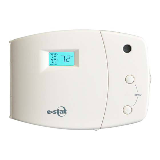
2-Way Communicating Thermostat
Hardware Installation and Operation Manual
.....INSTALLERS....
CONTACT LIGHTSTAT FOR ACTIVATION
1-800-292-2444
Intended for connection to
Class 2 Circuit(s) Only (24 VAC)
Common Wire is Required
Manufactured by:
Lightstat Inc.
Barkhamsted, CT
www.lightstat.com
e-Stat
®
For
Model Thermostat
Advertisement

Related Manuals for Lightstat e-stat


Summary of Contents for Lightstat e-stat
- Page 1 ® 2-Way Communicating Thermostat Hardware Installation and Operation Manual ..INSTALLERS..CONTACT LIGHTSTAT FOR ACTIVATION 1-800-292-2444 Intended for connection to Class 2 Circuit(s) Only (24 VAC) Common Wire is Required Manufactured by: Lightstat Inc. Barkhamsted, CT www.lightstat.com e-Stat ® Model Thermostat...
- Page 2 Retail or restaurant interior area 1. Typically, the e-Stat should be located within a few feet of the network equipment such as the network switch. It may be located farther. The maximum Cat 5 cable run is 328 ft (100 meters).
-
Page 3: Standard Features
Description: e-Stat is a low voltage, solid state, automatic changeover, heating/cooling thermostat with digital display showing setpoints and room temperature. e-Stat is a 2-Way Communicating, remotely programmable thermostat. Standard Features: • Control of up to two stages of heating and cooling. - Page 4 . -Move to ON for gas heat . Fan controlled by limit switch. -Leave OFF for fan controlled by Lightstat in heat cycle(typical for electric heat ). This thermostat receives programming via Ethernet cable connection .
- Page 5 OF DAMPERS CONTACT OR OTHER TERMINALS EQUIPMENT. ® ON e-Stat RELAY LOAD: 1 AMP (MAX) @ 24VAC Remove the old thermostat from the wall making note of the wire colors on the back of the mounting kit provided. Thread the thermostat cable through the...
- Page 6 R - Hot Wire; one side of the control (20 - 30 VAC) transformer. If two hot wires are present (as with RC and RH) determine if they come from separate transformers. The e-Stat must be installed on a single transformer system. G - Fan Wire.
- Page 7 Front View - Front Door Open Cool 1 MONT UEWEDT HUF RISAT SUN R EMO TE TEMP C O O L S E T ERRO R HUMI DI TY Cool 2 Y ellow - Website program active S Y S T E M O F F NEW PROGRAM Heat 1 H E A T S E T...
- Page 8 Display Designators REMOTE TEMP MONTUEWEDTHUFRISATSUN Cool 1 ERROR COOLSET HUMIDITY Cool 2 SYSTEM OFF NEW PROGRAM HEATSET Heat 1 OVERRIDE Heat 2 AUTO FAN A - Output indicators. Illuminated “ON” and arrow indicates output is active. Flashing arrow and steady “ON” indicates output is being held on by time delay.
- Page 9 Wiring Layout e-Stat is used as a stand-alone thermostat to control a single HVAC system. Do not attempt to ® e-Stat control more than one HVAC unit with an Both Remote Temperature and Supply Air sensors e-Stat MUST BE installed for the to function properly.
-
Page 10: Remote Sensor Installation
Remote Sensor Installation The e-Stat must have both a remote temperature sensor and a supply air sensor installed. These sensors are supplied for each thermostat. Note: See Appendix B for remote temp and humidity sensor. Use #18 gauge 2-conductor thermostat cable between the e-Stat and the remote sensors. - Page 11 Supply Air Sensor Mount the Supply Air Sensor on the discharge air duct with the probe in the discharge air stream. The probe must be positioned horizontally or downward. Do not place on the bottom of the duct with the probe sticking up.
- Page 12 -Leave OFF for 3 minute compressor minimum run and minimum off time delays . -Move to ON for gas heat . Fan controlled by limit switch. -Leave OFF for fan controlled by Lightstat in heat cycle(typical for electric heat ). OFF ON This thermostat receives programming via Ethernet cable connection .
- Page 13 -Leave OFF for 3 minute compressor minimum run and minimum off time delays . -Move to ON for gas heat . Fan controlled by limit switch. -Leave OFF for fan controlled by Lightstat in heat cycle(typical for electric heat ). OFF ON This thermostat receives programming via Ethernet cable connection .
- Page 14 When controlling fossil fueled equipment with a fan limit control, you may want to set this switch to the ON position. Note: The e-Stat will not bring on the fan in this setting during the heat cycle. Leave this switch set to OFF for all other...
- Page 15 S ensor Dry contacts (Max) @ are isolated . 24VAC e-Stat Use #18 gauge cable between the and the damper or equipment to be controlled. Cables do not need to be shielded. The A1-A2-A3 terminals are an isolated set of dry contacts rated 1 Amp at 24 VAC.
- Page 16 (see page 16 for activation instructions). You must connect the Cat 5 RJ45 jack in order for the e-Stat to communicate on the network and be programmed. ETHERNET CABLE (NETWORK) WIRING DIAGRAM...
- Page 17 2. Store Number. 3. Thermostat TUID number (yellow label affi xed on the inside wrap of the thermostat). During the activation, Lightstat Support will be able to bring on the heating and/or cooling for you to verify proper equipment operation. e-Stat...
- Page 18 Green Button Functions Check - Cancels all time delays (primarily used for troubleshooting purposes). Fan On/Auto - Some model thermostats may not have a selectable fan function. If selectable, choose be- tween “ON” (Constant Fan) or “AUTO” (Fan only with heat or cool cycle) during OCCUPIED period.
-
Page 19: Setting Temperature
If the temperature buttons function and they are used, the word “OVERRIDE” will appear in the display. The override period is determined by the communications interface. When the override period expires, the e-Stat will revert back to its program. e-Stats Note: Not all allow button adjustment of temperature settings during the OCCUPIED period. - Page 20 Output Status e-Stat Your will show the status of the HVAC system outputs. It will indicate when the Fan, Heating or Cool- ing should be running. ® e-Stat When you see “◄” ON in the display, the turning that output on.
- Page 21 Indicator Lights e-Stat contains (4) indicating lights: Yellow Green Blue Red Cool 1 R EMO TE TEMP MONT UEWEDT HUF RISAT SUN C O O L S E T ERRO R Cool 2 HUMI DI TY Y ellow - Website...
- Page 22 2. No Power to es, circuit break- equipment or e-Stat ® ers, fuses, gas valve and pilot. 3. Check display 3. e-Stat at limit to verify the e-stat temperature is set at its Cool- ing Minimim or Heating Maximum. Display does not 1.No Power to the...
- Page 23 24 VAC. 2. The e-Stat re- 2. Remove all out- sets when outputs put wires except come on. “R” & “C”. Then reconnect the wires one by one.
- Page 24 Wire the load such that the A relay is in the “normal” position. This will keep the load ON when the e-Stat A relay is powered off. The web program logic will as- sume it is wired this way.
- Page 25 Appendix B Using the (optional) Humidity Temperature Adjustment e-Stat Connecting the RTH sensor allows the to read and display relative humidity (%) as well as temperature. Yellow LED “Temperature + Humidity” The yellow LED in the center of the sensor will turn on...
- Page 26 There are times of the year (especially Spring and Fall) when temperatures may be at the proper setting, but high humidity can cause discomfort. e-Stat can automatically lower the programmed cooling setting by 2 °F when a pre-selected Relative Humidity (RH) setting is exceeded.
- Page 27 This device complies with Part 15 of the FCC rules. Operation is subject to the following two conditions: (1) this device may not cause harmful interference and (2) this device must accept any interference received, including interference that may cause undesired operation.
- Page 28 Product. Lightstat does not authorize any other person or organization to assume for it any liability in connection with this Product and any statements or representations made by any other person or organization are void.
Need help?
Do you have a question about the e-stat and is the answer not in the manual?
Questions and answers