Advertisement
INSTALLATION & OPERATION
MANUAL
Model TME-____________________*
* Balance of model number is determined by
customer specified limits and Setbacks.
AUTOMATIC SETBACK THERMOSTAT
LIGHT SENSING OR CONTACT CLOSURE
FOR LOW VOLTAGE (24VAC) SYSTEMS ONLY
REQUIRES A COMMON WIRE
Manufactured by:
LIGHTSTAT INC.
BARKHAMSTED, CT
(800)292-2444
www.lightstat.com
Advertisement
Table of Contents

Related Manuals for Lightstat TME series

Summary of Contents for Lightstat TME series
- Page 1 Model TME-____________________* * Balance of model number is determined by customer specified limits and Setbacks. AUTOMATIC SETBACK THERMOSTAT LIGHT SENSING OR CONTACT CLOSURE FOR LOW VOLTAGE (24VAC) SYSTEMS ONLY REQUIRES A COMMON WIRE Manufactured by: LIGHTSTAT INC. BARKHAMSTED, CT (800)292-2444 www.lightstat.com...
- Page 2 CONGRATULATIONS on your purchase of a Lightstat TME. It represents reliable, modern, electronic tempe rature control in addition to unique energy saving features. Features • 1 Amp relay switching of up to 6 HVAC loads. • Automatic Changeover from Heating to Cooling with a 5º F deadband between heating and cooling to prevent short cycling of equipment.
- Page 3 Relocate if necessary. The Lightstat TME senses a change in LIGHT LEVEL to determine Setback. Mount it under lights that GO OFF when people GO HOME. Locate the Lightstat TME at least 10 feet from a night light.
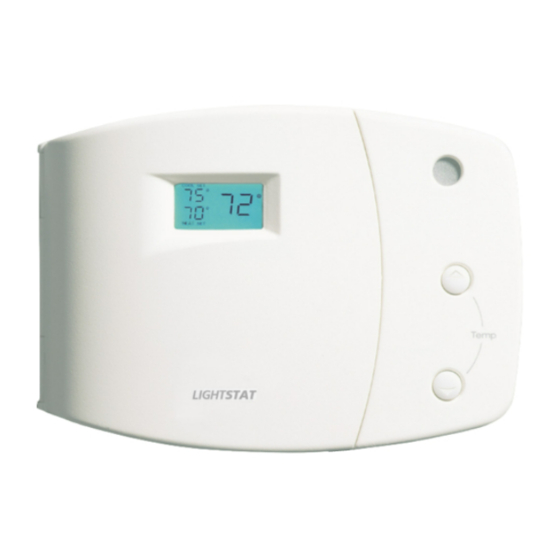
- Page 4 Description A - Current temperature. B - Indicates if SUPPLY, REMOTE, or ROOM temperature is being displayed. C - Setback indicator light. Glows green during Setback. D - Visual Alarm light. Flashes red during a Roof Top Alarm signal. E - Toggles temperature display between ROOM and SUPPLY air. F - Temperature adjustment buttons.
-
Page 5: Connecting The Outputs
Thread the thermostat cable through the hole on the back of the Lightstat TME. Mount the Lightstat TME securely to the wall using the hardware provided. The Lightstat TME should be leveled for cosmetic reasons. -
Page 6: System Layout
System Layout The Lightstat TME is used as a stand-alone thermostat to control a single HVAC system. Do not attempt to control more than one HVAC unit with a Lightstat TME. You can add a Remote Room Sensor to sense temperature remotely. - Page 7 This is a field option. You might not use this option with your Lightstat TME. You may add this in the field to an existing Lightstat TME. Mount the Remote Room Sensor on the wall 5’ to 7’ off the floor, in the area to be controlled.
- Page 8 This is a field option. You might not use this with your Lightstat TME. You may add this in the field to an existing Lightstat TME. Mount the Supply Air Sensor on the supply air duct securely with the probe horizontal or downward.
- Page 9 A1-A2 cable does not have polarity, either wire may be connected to either terminal. Cables do not have to be shielded. At the Lightstat TME end connect the cable to the two terminals marked A1 and A2. At the other end, connect it to the damper or equipment.
- Page 10 C1- C2 cable does not have polarity, either wire may be connected to either terminal. Cables do not have to be shielded. At the Lightstat TME end connect the cable to the two terminals marked C1 and C2. At the other end connect it to the customer supplied switch or alternate closed contact.
- Page 11 The Lightstat TME has a visual alarm to indicate that there is a problem with the Roof Top Unit (RTU). This is a field option. You might not have this option with your specific RTU. Use #18 gauge 2-conductor cable between the Lightstat TME and the RTU. The alarm is unaffected by wire runs of up to 1000 feet.
- Page 12 Setting the Heat Pump / Conventional Switch (#1) Note: The Lightstat TME must be powered Off and On in order to “read” a change of switch settings. Moving this switch to the ON position will increase the heating Setback by 5° (F). This will allow a heat pump to stay in a compressor mode longer and avoid expensive electric resistance heat.
- Page 13 Setting the Compressor Time Delay Switch (#2) Note: The Lightstat TME must be powered Off and On in order to “read” a change of switch settings. When this switch is set to OFF, the minimum On and Off time for any stage of Heating or Cooling will be 3 minutes.
- Page 14 Setting the O/B (Aux) Switch (#3) Note: The Lightstat TME must be powered Off and On in order to “read” a change of switch settings. The position of the O/B switch will determine whether the O/B output comes on with a call for Heating or for Cooling.
- Page 15 When controlling fossil fueled equipment with a fan limit control you may want to set this switch to the On position. Note: The Lightstat TME will not bring on the fan in this setting during the heat cycle. Leave this switch set to Off for all other equipment.
- Page 16 Setting the Remote Room Sensor Switch (#5) Note: The Lightstat TME must be powered Off and On in order to “read” a change of switch settings. This will tell the Lightstat TME to ignore the on-board temperature sensor. You will see the word REMOTE appear in the display indicating the Remote Room Sensor switch has been moved to ON.
- Page 17 Saturday but only open a few hours on Sunday; choose 11 hours and set the dial to “B”. The Lightstat TME will go back into Setback if the lights remain off after the Pre- Condition period. Thus, if a facility is closed on Sunday, the Lightstat TME will go...
- Page 18 First you must turn on the breaker or switch that feeds power to your Lightstat TME. Next press the System On/Off button, if necessary, to turn on the Lightstat TME. The power-up sequence will give you information on your Lightstat TME.
- Page 19 The clear plastic window on the top of your Lightstat TME is where it senses the light. If you shadow the window at the top of the Lightstat TME, it will cause it to shift to the Setback mode. It will signal this by turning on the GREEN SETBACK LIGHT.
- Page 20 Using the Lightstat TME Use the SYSTEM ON/OFF button to turn your HVAC equipment On and Off. Use the DISPLAY button to shift the temperature display from ROOM temperature to SUPPLY temperature. The SUPPLY temperature is the air temperature coming from your HVAC system. You will have to install a Supply Air Sensor in order to read this temperature.
- Page 21 If you see the word DELAY flashing, then the Lightstat TME is in a time delay. The startup time delay can be as long as 12 minutes.
-
Page 22: Setting The Temperature
COOL LIMIT. The display will flash COOL SET ‘AT MINIMUM’. The heating setpoint can continue to be adjusted lower. The HEAT LIMIT and COOL LIMIT for your model Lightstat TME are identified during the power-up sequence. See page #18 for more information. -
Page 23: Output Status
Your Lightstat TME will tell you what the output status of the HVAC system is. When you see the word ON in the display, the Lightstat TME is turning that output On. A flashing ◄ (arrow) next to the word ON means that the output is held on for a minimum time period;... - Page 24 You can also force the Cooling on by pushing the Down Button and the CHECK button at the same time. This will force the cooling on while you are pressing both buttons. Make sure that the Lightstat TME is in the occupied mode when you do this. The Green Setback light should be Off.
-
Page 25: Visual Alarm
Visual Alarm Your TME is equipped with a visual alarm which will allow you to know if there is an issue with your Roof Top Unit (RTU). This helps in preventing a small problem from becoming a large one, thus saving time, money and RTU down-time. -
Page 26: Basic Troubleshooting
See Light Adjustment on Page Setback. Lightstat TME at limit Check Display to verify the temperature. Lightstat TME is set at its Cooling Minimum or Heating Maximum. Display does not No power to the Lightstat Verify 24 VAC is present at come on during TME. - Page 27 24VAC. The Lightstat TME resets Check for a wiring short. when outputs come on. The cooling The Lightstat TME is at its The Lightstat TME has owner temperature can be heating maximum. specified Limits to prevent set higher but not overheating.
- Page 28 Customer. In no event, shall Lightstat be responsible for any monetary damage or be liable for any incidental or consequential damages due to any cause whatsoever, including, without limitation, commercial loss or damage resulting from an alleged defect in the Product.
Need help?
Do you have a question about the TME series and is the answer not in the manual?
Questions and answers