Page 1
V0.4 P21更改updating灯显; X1-2.0-S-N 将所有X1-mini改为X1&封皮修改。 朱伟 2016/4/21 V0.5 GFCI fault 改为rcd/rc fault; usb烧录要求:PV输入电压大于100V。 Copy Declaration The copyright of this manual belongs to SolaX Power Co.,Ltd.. Any corporation or 朱伟 2016/4/26 individual should not plagiarize, partitially copy or V0.6 THD改成小于2%. 朱伟 2016/5/12 V0.7 P17 AC连接线线径2mm²改成12AWG...
Page 2
The copyright of this manual belongs to SolaX Power Co.,Ltd.. Any corporation or individual should not plagiarize, partitially or fully copy(including software,etc.), and no reproduction or distribution of it in any form or by any means. All rights reserved. SolaX Power Co.,Ltd,.reserves 614.00098.01...
Page 3
Contents ............1 NOTES ON THIS MANUAL 1.1 SCOPE OF VALIDIT Y ................................1.2 TARGET GROUP ..................1.3 SYMBOLS USED ......................2 SAFETY ................2.1 APPROPRIATE USAGE ........... 2.2 IMPORTANT SAFET Y INSTRUC TIONS ......... 2.3 PE CONNEC TION AND LEAKAGE CURRENT ............
Page 4
9 DECOMMISSIONING ................9.1 DECOMMISSIONING ..........9.2 STORAGE AND TRANSPORTATION ....................9.3 DISPOSAL inverters. X1-1.1-S-N X1-1.5-S-N X1-2.0-S-N X1-1.1-S-D X1-1.5-S-D X1-2.0-S-D Note: “1.1” means 1.1kW. ”S” means “single” or one MPPT string. “D” means with “DC Switch”, ”N” means without “DC Switch”.
Spark gap devices are not suitable to be used in DC circuits once conducting, they won’t stop conducting until the voltage across their terminals is typically more than 30 volts. CAUTION! For X1-1.1-S-N, X1-1.5-S-N, X1-2.0-S-N, external dc breaker must be connected on the PV side.
Please keep the user manual properly. Caution ! Use only attachments recommended or sold by SolaX. Otherwise may Danger of burn injuries due to hot enclosure parts! result in a risk of fire, electric shock, or injury to person.
2.3 PE Connection and Leakage Current 2.4 Explanation of Symbols This section gives an explanation of all the symbols shown on the inverter and • The end-use application shall monitor the protective conductor by residual on the type label. current operated protective device (RCD) with rated fault current Ifn≤240mA which automatically disconnects the device in case of a fault.
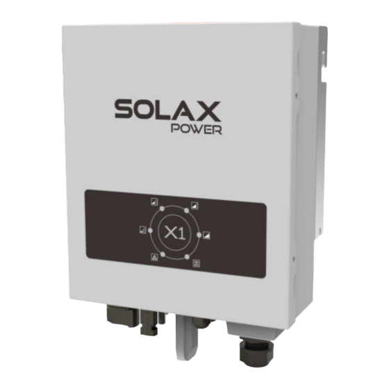
3. Instruction 3. Introduction Congratulations on your purchase of a X1 Series inverter from SolaxPower company. The X1 Series inverter is one of the finest inverter on the market nowadays, incorporating state-of-the-art technology, cost-effective, high reliability. Optimal MPPT technology. Advanced anti-islanding solutions. Excellent protections.
Page 9
124mm 248mm X1-1.1-S-D X1-1.5-S-D X1-2.0-S-D Model X1-1.1-S-N X1-1.5-S-N X1-2.0-S-N Max.PV Input Power 1250W 1650W 2200W Max.PV Voltage 400V 400V 400V Nominal Voltage 360V MPPT Voltage Range 70~380V 70~380V 70~380V Max.PV Current ISC PV MPPT Tracking No. No. of PV Input X1-1.1-S-D...
4. Technical data X1-1.1-S-D X1-1.5-S-D X1-2.0-S-D Model X1-1.1-S-N X1-1.5-S-N X1-2.0-S-N Operation Mode Euro - Efficiency 95.5% 96% 96.5% 97.1% 97.1% 97.1% Max.Efficiency [Waiting Mode] MPPT Efficiency 99.9% 99.9% 99.9% Safety & Protection Over Voltage Protection checking if PV array has enough power to feedback into grid.
Page 11
6.1 Packaging Description Remark Expansion tube Expansion screw Screw Cross recessed screw package 1.1~2kw 2 expansion screws Ring terminal tubes; Position Min.size Left Right Quick installation AC terminal Pocket WiFi (optional) Preparation...
Page 12
6.5.1 The Main Steps to Connect The Inverter PV String 1.1 kw - 2.0 kw X1 series inverter have one-string PV connector. X1-1.1-S-D X1-1.5-S-D X1-2.0-S-D Model X1-1.1-S-N X1-1.5-S-N X1-2.0-S-N Max.DC Voltage 400V 400V 400V connected inverter only after eliminating these problems.
AC Output Connection X1 series inverter are designed for single phase grid. Voltage range is recommended X1-1.1-S-D X1-1.5-S-D X1-2.0-S-D Model X1-1.1-S-N X1-1.5-S-N X1-2.0-S-N Cable 12AWG 12AWG 12AWG Micro-Breaker X1 series...
Page 14
You can read the real time data in the internet either from PC or smartphone with WiFi monitoring. stripped Connection Step: 1. Open the WiFi lid on the back of the inverter. 2. Plug the Pocket WiFi (from Solax) into the port named “WiFi” on inverter, and tighten the four screws as below.
Page 15
3. Connect the WiFi with the router. ( Please refer to “WiFi Setting Guide”.) Connection steps 4. Set the station account on the Solax web. (Please refer to “WiFi Setting Guide”.) Cable Color RS 485 Converter Blue 6.5.2 Communication Interface...
Connection steps During updating, don’t switch off the DC switch or cut off the 1. Choose at least 1mm² wire. Trip the insulation from the wire ends. external dc breaker! 2. Insert the tripped wire into the hole of the terminal block. 3.
Page 17
Fault(red) Normal(green) greater 100V Under this mode, the green light “a” is ickering, shown as gure . Ⅱ Checking: Inverter will check output environment automatically when DC operating output voltage of PV panels. Under this mode, the green light “a” is ickering, shown as gure Ⅲ...
Page 18
Indicator Light Explanation Indicate normal / error a, b c, d, e, f Indicate output power or the type of error First, read all indicator lamps, if the state of lamps “a” to “f” is ” bright, unlit, bright, bright, unlit, unlit”, the corresponding gures is ” ”...
- Are the cables adequately sized and short enough? Mgr Eeprom Fault - Are the communication cable properly connected and undamaged? Please contact SolaX Power company customer service for further assistance. Comms Lost Include SPI,SCI Faults Please be prepared to describe details of your system installation and provide the model and serial number of the unit.
Need help?
Do you have a question about the X1-1.1-S-N and is the answer not in the manual?
Questions and answers