
Related Manuals for Intellinet 561358


Summary of Contents for Intellinet 561358
- Page 1 8‐Port Fast Ethernet PoE+ Web‐Smart Switch with 1 Gigabit Combo Port User Manual Model 561358 INT‐561358‐UM‐0816‐2 ...
- Page 2 8‐Port Fast Ethernet PoE+ Web‐Smart Switch with 1 Gigabit Combo Port 1 Contents Product Introduction .......................... 1 Product Overview ........................ 1 Features ............................. 1 Specifications .......................... 2 2.3.1 Front Panel ......................... 3 2.3.2 Rear Panel .......................... 5 Hardware Installation ........................... 6 Installation .......................... 6 3.1.1 Desktop/Horizontal Installation .................. 6 ...
- Page 3 8‐Port Fast Ethernet PoE+ Web‐Smart Switch with 1 Gigabit Combo Port QoS Setting .......................... 31 5.6.1 Priority Mode ........................ 32 5.6.2 Class of Service ‐ Port, 802.1p, IP/DS based .............. 33 5.6.3 TCP/UDP Port Based ...................... 34 Security............................. 35 5.7.1 MAC‐Address Binding ....................... 35 5.7.2 MAC Address Scan ...................... 36 5.7.3 TCP/UDP Filter ........................ 36 ...
-
Page 4: Product Introduction
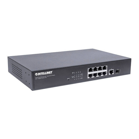
8‐Port Fast Ethernet PoE+ Web‐Smart Switch with 1 Gigabit Combo Port 2 Product Introduction 2.1 Product Overview The perfect solution to connect up to eight PoE‐enabled network cameras to your NVR! The Intellinet 8‐Port Fast Ethernet PoE+ Web‐Smart Switch with 1 Gigabit Combo Port (561358) is designed to pass both data and electrical power to a number of PoE‐compatible devices via standard Cat5e or Cat6 network cables. Equipped with eight Gigabit Ethernet ports (all of which support 802.3at/af PoE/PoE+), this switch can power wireless LAN access points and bridges, VoIP phones, IP video cameras and more while delivering network speeds of up to 1000 Mbps. The Intellinet 8‐ Port Fast Ethernet PoE+ Web‐Smart model is equipped with one 1‐Gigabit combo port. Available as both an on‐board RJ45 port and an optional SFP transceiver module slot, the Gigabit uplink port is ideal to connect the switch to the network's backbone, a server or your video recording solution (NVR). 2.2 Features • Provides power and data connection for up to eight PoE network devices • The ideal solution for connecting PoE‐enabled surveillance cameras to an NVR at Gigabit speeds • For use on desktops or mounted in standard 19" rack • Eight 10/100 Mbps IEEE 802.3at/af‐compliant RJ45 PoE ports and 1 Gigabit combo port • Supports IEEE 802.3at and IEEE 802.3af‐compliant PoE devices (wireless access points, VoIP phones, IP cameras) • Supports IEEE 802.3at/af detection and short circuit, overload and high‐voltage protection • Power output of up to 30 watts per port* • PoE power budget of 130 watts • 3.6 Gbps switch fabric •... -
Page 5: Specifications
8‐Port Fast Ethernet PoE+ Web‐Smart Switch with 1 Gigabit Combo Port 2.3 Specifications Standards • IEEE 802.1d (Spanning Tree Protocol) • IEEE 802.1p (Traffic Prioritization) • IEEE 802.1q (VLAN Tagging) • IEEE 802.3 (10Base‐T Ethernet) • IEEE 802.3ab (Twisted Pair Gigabit Ethernet) • IEEE 802.3ad (Link Aggregation Control Protocol LACP) • IEEE 802.3af (Power over Ethernet 802.3at Type 1) • IEEE 802.3at (Power over Ethernet 802.3at Type 2) • IEEE 802.3u (100Base‐TX Fast Ethernet) • IEEE 802.3x (flow control, for full duplex mode) General • Media support: ‐ 10Base‐T Cat3, 4, 5 UTP/STP RJ45 ‐ 100Base‐TX Cat5 UTP/STP RJ45 • Backplane speed / switch fabric: 3.6 Gbps • Switch architecture: store and forward • Certifications: FCC Class A, CE Power • Input: 100 – 240 VAC, 50 – 60 Hz • Power consumption: 150 watts (maximum) Environmental • Metal housing • Dimensions: 180 (L) x 278 (W) x 44 (H) [mm] (7.09 (L) x 10.94 (W) x 1.73 (H) [in]) • Weight: 1.9 kg (4.2 lbs.) • Operating temperature: 0 – 40°C (32 – 104°F) • Operating humidity: 10 – 90% RH, non‐condensing • Storage temperature: ‐20 – 70°C (‐4 – 158°F) Package Contents • 8‐Port Fast Ethernet PoE+ Web‐Smart Switch with 1 Gigabit Combo Port • 19" rackmount brackets • Power cable ... -
Page 6: Front Panel
8‐Port Fast Ethernet PoE+ Web‐Smart Switch with 1 Gigabit Combo Port 2.3.1 Front Panel The front panel of the Switch consists of eight 10/100 Mbps RJ‐45 ports, one 10/100/1000 Mbps RJ‐45 port, one 100/1000 Mbps (SFP) fiber port, one Reset button and a series of LED indicators shown as below. 10/100 Mbps RJ45 ports (1~8): Designed to connect to the device with a bandwidth of 10 Mbps or 100 Mbps. Each has a corresponding Link/Act and PoE Status LED. 10/100/1000 Mbps RJ45 port (9T): Designed to connect with a bandwidth of 10 Mbps, 100 Mbps or 1000 Mbps. 100/1000 Mbps SFP port (9S): Designed to install an SFP module. The switch features one SFP transceiver slot that are shared with one associated RJ45 port, port 9. The SFP port and associated RJ45 port are referred to as “Combo” port, which means they cannot be used simultaneously. It’s either‐or, but not both. Reset: Pressing this button for more than 3 seconds enables the Reset function. The system restores the factory default settings. LED indicators: The LED Indicators will allow you to monitor, diagnose and troubleshoot any potential problem with the switch, connection or attached devices. ... - Page 7 8‐Port Fast Ethernet PoE+ Web‐Smart Switch with 1 Gigabit Combo Port The following chart shows the LED indicators of the switch along with explanation of each indicator. LED COLOR STATUS STATUS DESCRIPTION On System start up SYS Green Off System upgrade or it did not start. On Power On Power Green Off Power Off On A device is connected to the port. Link/Act Green Flashing Sending or receiving data (1~8) Off A device is disconnected from the port. On A device is connected to the port. Link/Act Flashing Sending or receiving data Green (9T/S) Off A device is disconnected from the port. A Powered Device is connected to the port, On which is supplying power. Flashing ...
-
Page 8: Rear Panel
8‐Port Fast Ethernet PoE+ Web‐Smart Switch with 1 Gigabit Combo Port 2.3.2 Rear Panel The rear panel of the switch contains an AC power connector shown as below. AC Power Connector: Power is supplied through an external AC power adapter. It s upports AC 100-240V, 50/60Hz. Grounding Terminal: Located on the right side of the power supply connector, use grounded wire to prevent electric shock. ... -
Page 9: Hardware Installation
8‐Port Fast Ethernet PoE+ Web‐Smart Switch with 1 Gigabit Combo Port 3 Hardware Installation This part describes how to install your Ethernet switch and make connections to it. Please read the following topics and perform the procedures in the order being presented. 3.1 Installation Adhere to the instructions that follow in order to avoid incorrect installation, which will cause damage to the device and threaten security: Put the switch on a stable place or desktop to prevent it from falling. Make sure the switch operates within the proper AC input range and matches the voltage labeled on the switch. To prevent electrocution, do not open the switch’s chassis, even if it fails to receive power. Make sure that there is proper heat dissipation from and adequate ventilation around the switch. Make sure the surface on which the switch is placed can support the weight of the switch and its accessories. 3.1.1 Desktop/Horizontal Installation When installing the switch on a desktop , attach the enclosed rubber feet to the bottom corners of it to minimize vibration. Allow adequate space for ventilation between the device and the objects around it. 3.1.2 Rack‐mountable Installation in 11‐inch Cabinet The switch can be mounted in an EIA standard‐sized, 11‐inch rack, which can be placed in a wiring closet with other equipment. To install the switch, follow these steps: 1. -
Page 10: Power On The Switch
8‐Port Fast Ethernet PoE+ Web‐Smart Switch with 1 Gigabit Combo Port 2. Use the screws provided with the equipment rack to mount the switch on the rack and tighten it. 3.1.3 Power on the Switch The switch is powered on by the AC 100‐240V 50/60Hz internal high‐performance power supply. Follow the next tips to connect via an: AC Electrical Outlet Intellinet recommends using a single‐phase, three‐wire receptacle with a neutral outlet or multifunctional computer professional receptacle. Be sure to connect the metal ground connector to the grounding source on the outlet. AC Power Cord Connection Connect the AC power connector in the back panel of the switch to an external receptacle with the included power cord. Then, check that the power indicator is ON. When it is ON, the corresponding LED is illuminated. ... -
Page 11: How To Login The Switch
8‐Port Fast Ethernet PoE+ Web‐Smart Switch with 1 Gigabit Combo Port 4 How to Login the Switch 4.1 Connecting Computer Use standard Cat5/5e Ethernet cables (UTP/STP) to connect the switch to end nodes as described below. Switch ports will automatically adjust to the characteristics (MDI/MDI‐X, speed, duplex) of the device to which they are connected. _1.3.1 Front PanelThe Link/Act LEDs for each port are illuminated when the link is available. 4.2 How to Login the Switch As the switch provides Web‐based management login, configure your computer’s IP address manually to log on to the switch. The default settings of the switch are shown below. Parameter Default Value Default IP address 192.168.2.1 Default Username admin Default Password 1234 ... - Page 12 8‐Port Fast Ethernet PoE+ Web‐Smart Switch with 1 Gigabit Combo Port Log on to the configuration window of the switch through the following steps: 1. Connect the switch with the computer NIC interface. 2. Power on the switch. 3. Check whether the IP address of the computer is within this network segment: 192.168.2.xxx (“xxx” range is 2‐ 254); for example, 192.168.2.100. Open the browser, and go to the URL http://192.168.2.1. The switch login window appears as shown below. Enter the ID and Password (The default ID is admin, Password is 1234), and then click “OK” to log in to the switch configuration window as below. In the Web GUI, the left column shows the configuration menu and the rest of the screen area displays the configuration settings. ...
-
Page 13: Switch Configuration 1
8‐Port Fast Ethernet PoE+ Web‐Smart Switch with 1 Gigabit Combo Port 5 Switch Configuration This chapter describes how to use Web‐based management interface(Web UI) of the Intellinet switch’s software features. In the Web UI, the left column shows the configuration menu. The top row shows the switch’s current link status. Green squares indicate the port link is up, while gray squares indicate the port link is down. 5.1 Administrator 5.1.1 Authentication Configuration This screen allow you to change the administrator password. The default password is "1234". ... -
Page 14: System Ip Configuration
8‐Port Fast Ethernet PoE+ Web‐Smart Switch with 1 Gigabit Combo Port 5.1.2 System IP Configuration Item Description IP Address The LAN IP address of the switch. The default IP address is "192.168.2.1". Subnet Mask The default network mask is 255.255.255.0. Gateway The optional default gateway is only needed when you require Internet access for the Intellinet switch (e.g., in order to obtain time information from an NTP server). IP Configure Set to static (default) in order to set up the IP address of the Intellinet switch manually; set to DHCP for the Intellinet switch to receive IP address information from a DHCP server in your network. ... -
Page 15: System Status
8‐Port Fast Ethernet PoE+ Web‐Smart Switch with 1 Gigabit Combo Port 5.1.3 System Status This screen contains some system information for the switch—i.e., the device MAC address and the network name. You can also configure the idle time security. This parameter applies to the web administrator UI. In the example below, users will be automatically logged out after 30 minutes of inactivity. 5.1.4 Load default setting This feature restores all settings to factory default values. If you're locked out from configuring the switch and have lost access to the web admin interface, reinstate the factory default settings by pressing the reset button on the front of the switch for 5 seconds. ... -
Page 16: Firmware Update
8‐Port Fast Ethernet PoE+ Web‐Smart Switch with 1 Gigabit Combo Port 5.1.5 Firmware Update Intellinet may release new firmware for this switch, which may provide new functions and bug fixes. Install the new firmware on this screen. Should a new firmware be released, it will be available at http://intellinet‐ network.com/search?q=561358. How to install the new firmware: 1. Download the firmware from the website. 2. If the firmware is a compressed file such as RAR, 7Z or ZIP, uncompress the file first, before installing it on the Intellinet switch. 3. The correct file extension for the firmware is ".bin". 4. Click "Browse" and select the ".bin" file from your computer's HDD. 5. Type in the admin password, and then click " Upgrade." 6. Confirm your decision by clicking OK. 7. The upgrade will now begin. The first step is to erase the current firmware. 8. Select the new firmware from your HDD and begin uploading the new file. 5.1.6 Reboot Device Click "Restart" in order for the Intellinet switch to perform a system restart. ... -
Page 17: Poe Status
8‐Port Fast Ethernet PoE+ Web‐Smart Switch with 1 Gigabit Combo Port 5.2 PoE The Intellinet 8‐Port PoE+ Web‐Managed Switch is equipped with sophisticated PoE‐monitoring and configuration options. 5.2.1 POE Status This page is used to check POE Status, you can set Max Available Power here. Item Description Max available Power Define the maximum amount of available power for PoE devices. The maximum is 130 watts. System Operation Status Provides a status indication for the PoE status. Displays “on” if everything is working normally. Main Power Consumption Displays the power (watt) that is currently being drawn from the Intellinet PoE switch. Device Temperature Information about the current chipset temperature of the Intellinet switch. ... -
Page 18: Poe Settings
8‐Port Fast Ethernet PoE+ Web‐Smart Switch with 1 Gigabit Combo Port 5.2.2 POE Settings Item Description Port No. Select the port(s) for which you want to make changes to the configuration, and then click to save the settings. Status Enable: The port can provide power to a PoE edge (PD) device. Disabled: PoE support is deactivated; however, the port can still function as a regular Ethernet port. Mode Select the mode to be either “AF” or “AT.” The updated IEEE 802.3at‐2009 PoE standard, also known as PoE+, provides a higher output power rating as well as dynamic power distribution. Since it is backward compatible to the older “AF” standard, setting the mode to “AT” is generally recommended, unless you experience problems with legacy equipment. Priority You can choose form three priority levels. If the PoE budget is used up, the priority parameter controls, which ports get priority over other ports. Mission critical devices should be set to the value “critical” to make sure that they always receive power. Power Budget This parameter defines the maximum available power per port. The maximum value is 36 watt. Port Status This table shows the current state of the PoE configuration and connected PoE devices: Click to update the information. ... -
Page 19: Poe Power Delay
8‐Port Fast Ethernet PoE+ Web‐Smart Switch with 1 Gigabit Combo Port 5.2.3 PoE Power Delay The Intellinet switch offers an impressive array of PoE‐related management features, one of which is the PoE Power Delay feature. This function allows you to program a startup sequence for your PoE‐compliant devices and eliminate potential problems caused by the increased power draw at startup. The sequential power‐up guarantees a smooth startup procedure for all connected networking devices (i.e., your PoE‐enabled network cameras). Item Description Delay Mode Enable: Activate delay mode for the port(s) selected. Disable: Deactivates delay mode for the port(s) selected. Delay Time Sets the delay (in seconds) for each port to activate PoE. The example below shows a setup where we add a delay of 5 seconds for each of the PoE ports in order to minimize the power spike when the switch is powered on. ... -
Page 20: Poe Scheduling
8‐Port Fast Ethernet PoE+ Web‐Smart Switch with 1 Gigabit Combo Port 5.2.4 PoE Scheduling The Intellinet switch is equipped with a PoE scheduler that allows activating or deactivating PoE support for any of the eight PoE ports independently. Item Description Schedule on Port Select the port for which you want to create a schedule. Schedule Mode Define whether you want to activate or deactivate PoE for the selected port. This feature serves as a white/black list. Schedule AM/PM Specify whether you want to create a schedule for the morning hours (“A.M.”) or afternoon (“P.M.”). Note that in order for the scheduler to work, you have to provide the Intellinet switch with proper time server settings. Read on in order to find out how. ... -
Page 21: Ntp Setting
8‐Port Fast Ethernet PoE+ Web‐Smart Switch with 1 Gigabit Combo Port 5.2.5 NTP Setting On this screen, set up the Intellinet switch to connect to an NTP server. The Network Time Protocol (NTP) is a networking protocol for clock synchronization between computer systems over packet‐switched, variable‐latency data networks. If you plan on using the PoE scheduler (see section 5.2.4), you must set up NTP. Item Description NTP Enable Activate or deactivate NTP. System Time Displays the current system time of the Intellinet switch. NTP Server Provide two IP addresses for two different NTP servers. These can be external NTP servers or NTP servers inside your network. When using external NTP servers, make sure that: a) you set up a proper gateway IP address (see 5.1.2 System IP Configuration) and b) UDP port 123 is opened in your Firewall. Time Zone Select the time zone of your location. Note that the Intellinet switch will not automatically adjust for Daylight Saving Time, which means you'll need to make a manual adjustment to the time zone twice per year. ... -
Page 22: Port Management
8‐Port Fast Ethernet PoE+ Web‐Smart Switch with 1 Gigabit Combo Port 5.3 Port Management This section enables the user to make basic and advanced configuration changes to the ports of the Intellinet switch. 5.3.1 Port Configuration This section provides access to the core features of each of the 9 ports of your Intellinet switch. Item Description Tx/Rx Ability Activate or deactivate the port. Auto‐Negotiation Autonegotiation is an Ethernet procedure by which two connected devices choose common transmission parameters such as speed, duplex mode and flow control. Speed Set the link speed of the port to either 10 or 100 Mbps for ports 1 – 8. Additionally, port 9 can be set to 1 Gbps. Duplex Set the port to either full or half duplex. Pause Enable or disable IEEE 802.3x flow control. Backpressure Backpressure flow control causes a switch to hold off on sending data packets until the switch’s bottleneck has been eliminated. Address Learning Activate or deactivate. If activated, the Intellinet switch will learn the MAC addresses on this port and store them in its MAC address table. ... -
Page 23: Port Mirroring
8‐Port Fast Ethernet PoE+ Web‐Smart Switch with 1 Gigabit Combo Port 5.3.2 Port Mirroring Port mirroring is the ability of a network switch to send a copy of network packets seen on a switch port or ports to a network‐monitoring device connected to another switch port (i.e., a computer equipped with a packet sniffer utility). Item Description Destination Port This is the port where the listening station is connected to. Specify more than one port, but consider that this is a performance intensive function, which can lead to slow‐downs as the Intellinet switch hardware is trying to cope with the additional load. Monitored Disable, Rx (Receive), Tx (Transmit) or Tx & Rx. Packets This function activates port mirroring and defines the direction of the monitored packets. Source Port Select one or more ports. Traffic bound for or originating from these ports is copied to the destination port(s). ... -
Page 24: Bandwidth Control
8‐Port Fast Ethernet PoE+ Web‐Smart Switch with 1 Gigabit Combo Port 5.3.3 Bandwidth Control This feature provides the ability to control the available bandwidth per port. Item Description Port No Select the port you wish to edit from the drop‐down list. Tx (Transmit) Provide a value to limit the Transmit data rate. Set to 0 for maximum speed. Rate Rx (Receive) Rate Provide a value to limit the Receive data rate. Set to 0 for maximum speed. Speed Base This value sets the multiplicator for the Tx and Rx values. “Low”: Each rate point is worth 32 kbps. “High”: Each rate point is worth 256 kbps (ports 1 – 8) and 2048 kbps on port 9. ... -
Page 25: Broadcast Storm Control
8‐Port Fast Ethernet PoE+ Web‐Smart Switch with 1 Gigabit Combo Port 5.3.4 Broadcast Storm Control Storm control prevents LAN interfaces from being disrupted by a broadcast storm. A broadcast storm occurs when broadcast packets flood the subnet, creating excessive traffic and degrading network performance. Errors in the protocol‐stack implementation or in the network configuration can cause a broadcast storm. The Intellinet switch allows configuring maximum allowed pps rate (“Threshold”) for all 9 ports. Item Description Threshold The valid range is 1 ~ 63. This value indicates the number of broadcast packets that are allowed to enter each port in one time unit. One time unit is 50 μs for Gigabit speed, 500 μs for 100 Mbps speed, and 5000 μs for 10 Mbps speed (μs = microsecond). Tx Rate Select the corresponding port. ... -
Page 26: Vlan Settings
8‐Port Fast Ethernet PoE+ Web‐Smart Switch with 1 Gigabit Combo Port 5.4 VLAN Settings In large networks, routers are used to isolate broadcast traffic for each subnet into separate domains. The Intellinet switch provides a similar service at Layer 2 by using VLANs to organize any group of network nodes into separate broadcast domains. VLANs confine broadcast traffic to the originating group and can eliminate broadcast storms in large networks. This also provides a more secure and cleaner network environment. The system supports VLAN based on port and VLAN based on tag. You can change the VLAN mode in the VLAN Mode page. 5.4.1 VLAN Mode The Intellinet switch provides two VLAN mode: Port‐based and Tag‐based VLAN. You can change the mode on this page: ... -
Page 27: Port‐Based Vlan
8‐Port Fast Ethernet PoE+ Web‐Smart Switch with 1 Gigabit Combo Port 5.4.2 Port‐Based VLAN Port‐Based (untagged) VLAN uses the physical ports on the Intellinet switch to assign them to a VLAN. The switch does not add a tag to a packet to identify it as a member of a certain VLAN. It simply keeps the traffic separated by keeping track of the stations and the ports they are connected to. In small networks with only very few switches, port‐based VLAN can get the job done, and it is easy to implement. Example of a port‐based VLAN setup: ... - Page 28 8‐Port Fast Ethernet PoE+ Web‐Smart Switch with 1 Gigabit Combo Port Result: Here is another example‐‐again, with two VLANs, but this time there is a router connected to port 8. We want all PCs to have access to the Internet, but the PCs in VLAN 1 and VLAN 2 cannot access one another. Port 8 is a member of both VLANs. ...
-
Page 29: Tag‐Based Vlan
8‐Port Fast Ethernet PoE+ Web‐Smart Switch with 1 Gigabit Combo Port 5.4.3 Tag‐Based VLAN In this mode, packets are tagged with a VLAN ID, which is added to the packet header in addition to the destination and source MAC addresses. Above: Both switches are connected with a single cable that carries tagged VLAN packets of both VLAN 1 and VLAN 2. Item Description VLAN TAG Mode Select whether to tag / untag based on the port or the VID selected below. VID Select the VLAN ID for which you want to define the port behavior below. This option is only available if “Tag/Untag base on VID” is selected in the option above. Add Tag Type Add Tag: Outgoing packets will be tagged regardless of whether or not the received packet has a VLAN tag. Don’t Care: Packets will be forwarded without removing or adding any VLAN tags. Remove Tag: The VLAN tag of the outgoing packet will be removed regardless of whether the received packet has a VLAN tag. ... - Page 30 8‐Port Fast Ethernet PoE+ Web‐Smart Switch with 1 Gigabit Combo Port Item Description VLAN Setting Displays for each port 1 to 9. Member Select Select to make the port a member of the VLAN ID. PVID Select If you do not select any port, this VID will be treated as the VID embedded in a 802.1Q tag. The following figure displays the VLAN configuration in the tag mode. ...
-
Page 31: Multi To 1 Setting
8‐Port Fast Ethernet PoE+ Web‐Smart Switch with 1 Gigabit Combo Port 5.4.4 Multi to 1 Setting The Multi‐to‐1 feature can be used for a very specific application. The same could be achieved with a port‐based VLAN setup, but the multi‐to‐1 setting makes it a bit easier to set up. When activated, each of the 9 ports will operate in its own VLAN and is shielded from any requests made by any other client. The destination port, however, is the one port that all ports can access. A typical example would be allowing access to the Internet for all PCs but shielding each PC from each other. Think of an Internet Café, for example. The example below shows a shared port 9 – i.e., the port to which the router is connected, and port 1 is disabled, which means port 1 cannot communicate with any of the other ports. Item Description Enable By activating this, you enable VLAN for all ports. When activated, none of the 9 ports can exchange data. Destination Port Select the one port that all other ports can access. Disable Port Any port you select here will not be able to access the destination port. ... -
Page 32: Non‐Association Port Setting
8‐Port Fast Ethernet PoE+ Web‐Smart Switch with 1 Gigabit Combo Port 5.4.5 Non‐Association Port Setting This feature is a variation of the previous function. When you use this feature, selected ports cannot communicate with each other. Example 1: Port 1 cannot communicate with port 2 and port 2 cannot communicate with port 1, but both ports can communicate with ports 3 – 9. Example 2: A router is connected to port 9, and PCs are connected to ports 1 – 8. We want to isolate all PCs from each other, but allow them to connect to port 9. ... -
Page 33: Per Port Counter
8‐Port Fast Ethernet PoE+ Web‐Smart Switch with 1 Gigabit Combo Port 5.5 Per Port Counter This page provides a port counter for each port. There are four groups of statistics in total. These four categories cannot work simultaneously. Once the counter category is changed, the counter will be cleared automatically. Available groups: ‐ Collision count & transmit packet ‐ Transmit packet & receive packet ‐ Receive packet & drop packet ‐ Receive packet & CRC packet Item Description Counter Mode Selection Select the category you wish to monitor and click the “Update” button. Clear Resets all counters. Refresh Reloads the screen with the most current information. ... -
Page 34: Qos Setting
8‐Port Fast Ethernet PoE+ Web‐Smart Switch with 1 Gigabit Combo Port 5.6 QoS Setting Quality of Service (QoS) is an advanced traffic prioritization feature that allows the user to establish control over network traffic. QoS enables the assigning of various grades of network service to different types of traffic such as multi‐media, video, protocol‐specific, time critical and file‐backup traffic. QoS reduces bandwidth limitations, delay, loss and jitter. It also provides increased reliability for delivery of data and allows for the prioritization of certain applications across your network. Define exactly how you want the switch to treat selected applications and types of traffic. Use QoS on your system to control a wide variety of network traffic by: • Classifying traffic based on packet attributes. • Assigning priorities to traffic (e.g., to set higher priorities to time‐critical or business‐critical applications). • Applying security policy through traffic filtering. • Providing predictable throughput for multimedia applications such as video conferencing or VoIP by minimizing delay and jitter. • Improving performance for specific types of traffic and preserving performance as the amount of traffic grows. • Reducing the need to constantly add bandwidth to the network. • Managing network congestion. ... -
Page 35: Priority Mode
8‐Port Fast Ethernet PoE+ Web‐Smart Switch with 1 Gigabit Combo Port 5.6.1 Priority Mode This page allows the user to set the scheduling mode for the TX packet's priority. Item Description First‐In‐First‐Out First‐in‐first‐out (FIFO) is the most basic queue schedule. In FIFO queuing, all packets are treated equally by placing them into a single queue and then servicing them in the same order that they were placed into the queue. FIFO queuing is also referred to as first‐come, first‐served (FCFS) queuing. All‐High‐before‐Low The Intellinet switch first forwards all the packets in a high‐priority queue then forwards those packets in low‐priority queue. Weight‐Round‐Robin The Intellinet switch forwards a specified number of high priority packets and then a specified number of low priority packets. The switch repeats this cycle continuously. “Low weight”: Number of packets in low priority queue “High weight”: Number of packets in high priority queue ... -
Page 36: Class Of Service ‐ Port, 802.1P, Ip/Ds Based
8‐Port Fast Ethernet PoE+ Web‐Smart Switch with 1 Gigabit Combo Port 5.6.2 Class of Service ‐ Port, 802.1p, IP/DS based This screen allows the user to configure the three class of services (port, 802.ap and IP/DS) and assign them a high priority. Item Description Port No.\Mode One line item for each of the 9 ports of the Intellinet switch. Port‐Based If activated, instructs the Intellinet switch to mark all traffic as high priority for the selected port. VLAN Tag VLAN tagged frames as defined by IEEE 802.1Q will be prioritized. The priority is determined according to the value of 802.1p (bit [15:13]) in the VLAN Tag. Packets in which values of 802.1p (bit [15:13]) are 000‐011 map to lower priority. Packets in which values of 802.1p (bit [15:13]) are 100‐111 map to higher priority. IP / DS For IPv4 packets, the priority is determined according to the value of TOS [5:0] in the header. Packets in which values of TOS [5:0] are 101110, 001010, 010010, 011010, and 11x000 map to higher priority. Packets in which TOS [5:0] are other values map to lower priority. ... -
Page 37: Tcp/Udp Port Based
8‐Port Fast Ethernet PoE+ Web‐Smart Switch with 1 Gigabit Combo Port 5.6.3 TCP/UDP Port Based CoS based on the TCP/UDP port specifies the priority queues of packets or discards designated protocol packets according to the application layer protocols of packets received at the port. CoS supports classifying packets into corresponding priority queues or discarding packets according to the port in the range of ports 1‐65535, besides certain known protocols, such as FTP, telnet, and SNMP. [ … ] Item Description Protocol Select from any of the pre‐programmed options, or create up to four user‐defined entries. Option F‐I‐F‐O: First in, first out. Discard: Don’t forward. Low: Forward with low priority. High: Forward with high priority. User‐Defined Port: The valid range is 1 ~ 65535. Mask: The valid range is 0 ~ 255. TCP/UDP port QoS function If set to “overwrite,” the Intellinet switch will ignore existing CoS rules as defined in section 5.6.2. ... -
Page 38: Security
8‐Port Fast Ethernet PoE+ Web‐Smart Switch with 1 Gigabit Combo Port 5.7 Security 5.7.1 MAC‐Address Binding After MAC‐address binding is enabled at a port, only devices whose MAC addresses are consistent with the bound MAC address can communicate through the port. A port can be bound to a maximum of three MAC addresses. Binding a MAC address to a specific port can help protect against spoofing attacks. If MAC address binding is enabled, address learning is automatically disabled, and RSTP/STP is affected. It is recommended to disable STP on the port. The configuration procedure: 1. Enter the MAC address. 2. Select the port that you want to bind a MAC address to. 3. Select Enable from the drop‐down list to enable the binding service. 4. Click Update. ... -
Page 39: Mac Address Scan
8‐Port Fast Ethernet PoE+ Web‐Smart Switch with 1 Gigabit Combo Port 5.7.2 MAC Address Scan On this page the network administrator can scan the MAC addresses for each port on the Intellinet switch of all currently connected devices. 5.7.3 TCP/UDP Filter The TCP/UDP port filter allows the user to filter out or allow packets bound for specific ports based on the protocol type used. Define for which of the nine ports you want to enable this function. These ports are referred to as secured WAN ports. The example below shows a setup in which port 9 is defined as a secured WAN port, and only FTP, HTTP, HTTPS, POP3 and SNMP are allowed. Any other protocol bound for port 9 will be dropped. Item Description Function Enable You guessed it: this activates or deactivates the TCP/UDP filter. Port Filtering Rule Negative: Selected protocols will be filtered out (black list). Positive: Only selected protocols are allowed, all others are filtered out (whitelist). Protocol Select the protocols that you wish to either filter out or specifically allow. Secure WAN Select the ports to which you want to apply the TCP/UDP filter rule. ... -
Page 40: Web Security
8‐Port Fast Ethernet PoE+ Web‐Smart Switch with 1 Gigabit Combo Port 5.7.4 Web Security If you want to limit access to the Intellinet switch's web administrator menu to a station that is connected to a specific port, you can use this feature to quickly set this up. The example below shows how to only allow access to the web administrator interface via port 1. Note: Be sure that you are connected to a port that will be allowed to access the web administrator interface after the function is activated, or you will lose access to the web admin interface just as soon as you hit the update button. ... -
Page 41: Spanning Tree
8‐Port Fast Ethernet PoE+ Web‐Smart Switch with 1 Gigabit Combo Port 5.8 Spanning Tree The Spanning Tree Protocol can be used to detect and disable network loops and to provide backup links between switches, bridges or routers. This allows the switch to interact with other bridging devices in your network to ensure that only one route exists between any two stations on the network and provide backup links, which automatically take over when a primary link goes down. The spanning tree algorithms supported by this switch include these versions: STP – Spanning Tree Protocol (IEEE 802.1D) – supported by Intellinet switch model 561358 RSTP – Rapid Spanning Tree Protocol (IEEE 802.1w) – supported by Intellinet switch model 561358 MSTP – Multiple Spanning Tree Protocol (IEEE 802.1s) – not supported The IEEE 802.1D Spanning Tree Protocol and IEEE 802.1w Rapid Spanning Tree Protocol allow for the blocking of links between switches that form loops within the network. When multiple links between switches are detected, a primary link is established. Duplicated links are blocked from use and become standby links. The protocol allows for the duplicate links to be used in the event of a failure of the primary link. Once the Spanning Tree Protocol is configured and enabled, primary links are established and duplicated links are blocked automatically. The reactivation of the blocked links (at the time of a primary link failure) is also accomplished automatically without operator intervention. This automatic network reconfiguration provides maximum uptime to network users. However, the concepts of the Spanning Tree Algorithm and protocol are a complicated and complex subject and must be fully researched and understood. It is possible to cause serious degradation of the performance of the network if the Spanning Tree is incorrectly configured. Please read the following before making any changes from the default values. ... -
Page 42: Stp Bridge Settings
8‐Port Fast Ethernet PoE+ Web‐Smart Switch with 1 Gigabit Combo Port 5.8.1 STP Bridge Settings Item Description STP Mode STP: Spanning Tree Protocol. RSTP: Rapid Spanning Tree Protocol. Disable: Deactivates spanning tree support. Bridge Priority The lower the value, the higher the priority. Any value entered must be a multiple of 4096 and should be in range of 0 ~ 61440. Hello Time This is the time between each bridge protocol data unit (BPDU) that is sent on a port. The default value is 2 seconds (sec), but you can set the time to a value between 1 and 10 sec. Max Age The max age timer controls the maximum length of time that passes before a bridge port saves its configuration BPDU information. This time is 20 sec by default. Possible values are between 6 and 40 sec. Forward Delay This is the time that is spent in the listening and learning state. This time is equal to 15 sec by default, but you can tune the time to be between 4 and 30 secs. ... -
Page 43: Stp Port Settings
8‐Port Fast Ethernet PoE+ Web‐Smart Switch with 1 Gigabit Combo Port 5.8.2 STP Port Settings Item Description Port No Select port 1 – 9 from the drop‐down list. Priority The valid range is 0 ~ 240. It should be a multiple of 16. RPC Root Path Cost. The valid range is 1 ~ 200000000. 0 indicates Auto. RPC determines the path cost that is from per port to the root bridge. The following table lists the recommended value. You can modify it during actual use. Speed IEEE Recommended Value Recommended Range 10 Mbps 100 50~600 100 Mbps 19 10~60 1000 Mbps 4 3~10 10G Mbps 2 1~5 ... -
Page 44: Loopback Detection
8‐Port Fast Ethernet PoE+ Web‐Smart Switch with 1 Gigabit Combo Port 5.8.3 Loopback Detection When loopback detection is enabled and a port receives its own BPDU, the detection agent drops the loopback BPDU and places the interface in discarding mode. This loopback state can be released automatically. Item Description Loopback Detection Function Enables/Disables (Default: disable) Auto Wake Up Configures the interface for automatic loopback release. Wake‐Up Time interval Defines the time interval for the port that will be released from the discarding state. ... -
Page 45: Trunking – Link Aggregation
8‐Port Fast Ethernet PoE+ Web‐Smart Switch with 1 Gigabit Combo Port 5.9 Trunking – Link Aggregation Port aggregation is a method of using multiple Ethernet ports in parallel to increase throughput beyond what a single connection could sustain and to provide redundancy in case one of the links should fail. As this is essentially a grouping of ports into one logical unit, we call them Link Aggregation Groups, or “LAG” for short. You can create multiple links between devices that work as one virtual aggregate link. A port trunk offers a dramatic increase in bandwidth for network segments where bottlenecks exist as well as providing a fault tolerant link between two devices. The Intellinet switch supports both static trunking and dynamic Link Aggregation Control Protocol (LACP). Static trunks have to be manually configured at both ends of the link. On the other hand, LACP‐configured ports can automatically negotiate a trunked link with LACP‐configured ports on another device. Note: While Port aggregation can quadruple the bandwidth between two Intellinet switches, as long as they are model 561358, there are two factors you should keep in mind before even considering this function: 1. Trunking wastes regular ports. In order to increase the bandwidth between two switches from 100 to 400 Mbps, you are going to have to use 8 ports (4 on each switch) instead of just 2 ports. 2. The Intellinet switch already provides a better method of uplinking, which is port 9. It provides 1 Gbps bandwidth and is ideally suited for connecting two switches together. ... - Page 46 8‐Port Fast Ethernet PoE+ Web‐Smart Switch with 1 Gigabit Combo Port Item Description System Priority Integer that indicates the LACP priority for the system. The range is from 0 to 65535. Assign a system priority to each switch running link aggregation. Specify the system priority or use the default system priority (32768). The system priority is used with the MAC address of the device to form the system ID and is used during negotiation with the other systems. Link Aggregation When configuring link aggregation on a switch that is link‐aggregation aware, you must select a Algorithm link aggregation algorithm. It is recommended (but not required) that the algorithms are the same on both switches. MAC SRC: Source MAC address. MAC SRC&DST: Source XOR destination MAC address. Item Description Member The Intellinet switch supports two link aggregation groups. Group 1 for ports 1 – 4, and group 2 for ports 5 – 8. Select up to four ports per group. State Enable or disable. ...
- Page 47 8‐Port Fast Ethernet PoE+ Web‐Smart Switch with 1 Gigabit Combo Port Item Description Type Static: All configuration settings must be set up manually, exactly the same way on the participating LAG device—i.e., the other Intellinet 24 Port PoE+ Web Managed Gigabit Switch. There is no problem with doing this, of course. Even the static method provides link redundancy, should one or more of the links in the trunk fail. However, if media converters are used, it can happen that the link on switch#1 is up, but the connection to switch#2 at the other end is interrupted (e.g., because of a cable malfunction). In this case, switch#1 keeps sending data via this connection because, on this end, there are no interruptions. The data transfer is therefore interrupted. LACP: Link Aggregation Control Protocol (LACP) allows the dynamic exchange of information with regard to the link aggregation between the two members of said aggregation. It allows for the automatic detection of links in an LAG group when connected to another LACP‐compliant Switch. Both switch#1 and switch#2 need to be set to the same mode for this to work. The data between the two switches is packetized in Link Aggregation Control Protocol Data Units (LACDUs). Should any of these packets fail to arrive, for instance due to an interruption on one side of the media converter, the switches will quickly remove the LAG group port, causing the problem from the LAG group. No data is lost. Select either static or LACP (recommended) on both switches. Operation Key LACP related operational key. Time‐Out Set to either long or short time‐out. If no LACPDUs (Link Aggregation Control Protocol Data Units) are received, this value specifies the timeout for the trunk. Activity Set to either passive or active. One switch should be set to active, the other to passive. Note: When you configure trunking, you need to disable the Pause and Backpressure of the corresponding port in the Port Configuration page in the Port management navigation – see section 5.3.1 Port Configuration. Submit to apply the settings. Afterwards, click Refresh to refresh the state of link group. When the “‐‐” in member configuration turns into “A,” it indicates that trunking has been established between the two ...
-
Page 48: Dhcp Relay
8‐Port Fast Ethernet PoE+ Web‐Smart Switch with 1 Gigabit Combo Port 5.10 DHCP Relay 5.10.1 DHCP Relay Agent A DHCP client is an Internet host using DHCP to obtain configuration parameters such as an IP address. A DHCP relay agent is any host that forwards DHCP packets between clients and servers. Relay agents are used to forward requests and replies between clients and servers when they are not on the same physical subnet. The Intellinet switch can fulfill the role of such a relay agent. Item Description DHCP Relay State Enable or disable DHCP relay. DHCP Relay Hops Count Limit (1‐16): Sets the maximum number of allowed hops in the BOOTP/DHCP header. DHCP Relay Option 82 state When enabled, the client that receives the DHCP message with option82 information will forward it; otherwise, it will be discarded. ... -
Page 49: Relay Server
8‐Port Fast Ethernet PoE+ Web‐Smart Switch with 1 Gigabit Combo Port 5.10.2 Relay Server On this page you provide the IP address of a valid DHCP server. 5.10.3 VLAN MAP Relay Agent On this page you can map a VLAN ID to a server IP. ... -
Page 50: Backup/Recovery
8‐Port Fast Ethernet PoE+ Web‐Smart Switch with 1 Gigabit Combo Port 5.11 Backup/Recovery This function allows the administrator to save the configuration data of the Intellinet 8‐Port Fast Ethernet PoE+ Web‐ Smart Switch to the computer’s HDD or another file location. 5.11.1 Backup Configuration Item Description Download Button Click this button in order to save the configuration. After a few seconds, a popup‐widow will appear. Save File Specify the location where you want to you want to store the file, then click “OK” to begin. ... -
Page 51: Restore Configuration
8‐Port Fast Ethernet PoE+ Web‐Smart Switch with 1 Gigabit Combo Port 5.11.2 Restore Configuration Item Description Password Provide the administrator password in order to restore a configuration. Select the image file Specify the location where the file is stored, then click “Update” to begin. ... -
Page 52: Miscellaneous
8‐Port Fast Ethernet PoE+ Web‐Smart Switch with 1 Gigabit Combo Port 5.12 Miscellaneous 5.12.1 Aging Time This function is used to avoid poor utilization of the Intellinet switch. When a packet is stored in a switch for a long time, it will expire from the allowable time defined by the protocol and become a useless packet. To prevent these packets from wasting the bandwidth, this switch provides an option for the administrator to enable the queue‐aging function. Item Description Aging Time Possible values are: disable, 200 ms, 400 ms, 600 ms, 800 ms. 5.12.2 VLAN Striding Under normal circumstances, a uni‐cast packet must not be forwarded to a port that is not a member of a VLAN; it must be dropped. VLAN Striding allows the uni‐cast packet to be forwarded across different VLANs without restrictions, and the packets will no longer be dropped. Item Description VLAN Striding Enable or disable VLAN Striding. ... -
Page 53: Igmp Snooping
8‐Port Fast Ethernet PoE+ Web‐Smart Switch with 1 Gigabit Combo Port 5.12.3 IGMP Snooping The Internet Group Management Protocol (IGMP) lets hosts and routers share information about multicast group memberships. IGMP snooping is a switch feature that monitors the exchange of IGMP messages and copies them to the CPU for future processing. The overall purpose of IGMP Snooping is to limit the forwarding of multicast frames to only ports that are a member of the multicast group. Computers and network devices that want to receive multicast transmissions need to inform nearby routers that they will become members of a multicast group. The Internet Group Management Protocol (IGMP) is used to communicate this information. IGMP is also used to periodically check the multicast group for members that are no longer active. In the case where there is more than one multicast router on a sub network, one router is elected as the "queried." This router then keeps track of the membership of the multicast groups that have active members. The information received from IGMP is then used to determine if multicast packets should be forwarded to a given sub network or not. Using IGMP, the router can check to see if there is at least one member of a multicast group on a given sub network. If there are no members on a sub network, packets will not be forwarded to that sub network. Multicast Service Enable or disable IGMP Snooping on this screen as well as activate or deactivate IGMP Leave Packet support. ... -
Page 54: Vlan Uplink Setting
8‐Port Fast Ethernet PoE+ Web‐Smart Switch with 1 Gigabit Combo Port 5.12.4 VLAN Uplink Setting Configure a subset of the ports in a port‐based VLAN as uplink ports. The Intellinet switch sends all broadcast and unknown‐unicast traffic from a port in the VLAN to the uplink ports, but not to other ports within the VLAN. Thus, the uplink ports provide tighter broadcast control within the VLAN. For example, if one port within a port‐based VLAN is a Gigabit port (port 9) and the other ports are 10/100 Mbps ports attached to clients, you can configure the Gigabit port as an uplink port. In this configuration, broadcast and unknown‐ unicast traffic in the VLAN does not go to all ports. The traffic goes only to the uplink port. The clients on the network do not receive broadcast and unknown‐unicast traffic from other ports, including other clients. Item Description Port 01 ‐ 09 Activate Uplink 1 and Uplink 2 for one of the 9 ports. Clear Uplink Use this to deselect a previously selected uplink port. Update Click to activate the setting. ... -
Page 55: Snmp Settings
8‐Port Fast Ethernet PoE+ Web‐Smart Switch with 1 Gigabit Combo Port 5.13 SNMP Settings Simple Network Management Protocol (SNMP) is an OSI Layer 7 (Application Layer) designed specifically for managing and monitoring network devices. SNMP enables network management stations to read and modify the settings of gateways, routers, switches and other network devices. Use SNMP to configure system features for proper operation, monitor performance and detect potential problems in the Switch, switch group or network. Item Description Community Settings Provide the SNMP community names and corresponding access rights (read only or read+write). SNMP Settings Provide the values for the SNMP parameters System Description, System Contact and Location. SNMP Trap Settings SNMP traps are alerts generated by agents on a managed device. Trap‐State: Enable or Disable SNMP traps. Enable Trap Server: Enable or disable an external SNMP trap server. Trap Server Address: The IP address of the SNMP manager (TRAP viewer). ... -
Page 56: Logout
8‐Port Fast Ethernet PoE+ Web‐Smart Switch with 1 Gigabit Combo Port 5.14 Logout In order to end your session, use the logout function. Click “Accept” in order to logout from the Intellinet web administrator interface. ... -
Page 57: Warranty 5
8‐Port Fast Ethernet PoE+ Web‐Smart Switch with 1 Gigabit Combo Port 6 Warranty Deutsch ‐ Garantieinformationen finden Sie hier unter intellinetnetwork.com/warranty. English ‐ For warranty information, go to intellinetnetwork.com/warranty. Español ‐ Si desea obtener información sobre la garantía, visite intellinetnetwork.com/warranty. Français ‐ Pour consulter les informations sur la garantie, rendezvous à l’adresse intellinetnetwork.com/warranty. Italiano ‐ Per informazioni sulla garanzia, accedere a intellinetnetwork.com/warranty. Polski ‐ Informacje dotyczące gwarancji znajdują się na stronie intellinetnetwork.com/warranty. México ‐ Póliza de Garantía Intellinet — Datos del importador y responsable ante el consumidor IC Intracom México, S.A.P.I. de C.V. • Av. Interceptor Poniente # 73, Col. Parque Industrial La Joya, Cuautitlan Izcalli, Estado de México, C.P. 54730, México. • Tel. (55)1500‐4500 La presente garantía cubre los siguientes productos contra cualquier defecto de fabricación en sus materiales y mano de obra. A. Garantizamos cámaras IP y productos con partes móviles por 3 años. B. Garantizamos los demás productos por 5 años (productos sin partes móviles), bajo las siguientes condiciones: 1. Todos los productos a que se refiere esta garantía, ampara su cambio físico, sin ningún cargo para el consumidor. 2. El comercializador no tiene talleres de servicio, debido a que los productos que se garantizan no cuentan con reparaciones, ni refacciones, ya que su garantía es de cambio físico. 3. La garantía cubre exclusivamente aquellas partes, equipos o sub‐ensambles que hayan sido instaladas de fábrica y no incluye en ningún caso el equipo adicional o cualesquiera que hayan sido adicionados al mismo por el usuario o distribuidor. Para hacer efectiva esta garantía bastará con presentar el producto al distribuidor en el domicilio donde ue adquirido o en el domicilio de IC Intracom México, S.A.P.I. de C.V., junto con los accesorios contenidos n su empaque, acompañado de su póliza debidamente llenada y sellada por la casa vendedora indispensable el sello y fecha de compra) donde lo adquirió, o bien, la factura o ticket de compra original donde se mencione claramente el modelo, numero de serie (cuando aplique) y fecha de adquisición. Esta garantía no es válida en los siguientes casos: Si el producto se hubiese tilizado en condiciones distintas a las normales; si el producto no ha sido operado conforme a los instructivos de uso; o si el producto ha sido alterado o tratado de ser reparado por el consumidor o terceras personas. ... -
Page 58: Copyright 5
8‐Port Fast Ethernet PoE+ Web‐Smart Switch with 1 Gigabit Combo Port 7 Copyright Copyright ©2016 IC Intracom. All rights reserved. No part of this publication may be reproduced, transmitted, transcribed, stored in a retrieval system, or translated into any language or computer language, in any form or by any means, electronic, mechanical, magnetic, optical, chemical, manual or otherwise, without the prior written permission of this company This company makes no representations or warranties, either expressed or implied, with respect to the contents hereof and specifically disclaims any warranties, merchantability or fitness for any particular purpose. Any software described in this manual is sold or licensed "as is". Should the programs prove defective following their purchase, the buyer (and not this company, its distributor, or its dealer) assumes the entire cost of all necessary servicing, repair, and any incidental or consequential damages resulting from any defect in the software. Further, this company reserves the right to revise this publication and to make changes from time to time in the contents thereof without obligation to notify any person of such revision or changes. ... -
Page 59: Federal Communication Commission Interference Statement 5
8‐Port Fast Ethernet PoE+ Web‐Smart Switch with 1 Gigabit Combo Port 8 Federal Communication Commission Interference Statement This equipment has been tested and found to comply with the limits for a Class B digital device, pursuant to Part 15 of FCC Rules. These limits are designed to provide reasonable protection against harmful interference in a residential installation. This equipment generates, uses, and can radiate radio frequency energy and, if not installed and used in accordance with the instructions, may cause harmful interference to radio communications. However, there is no guarantee that interference will not occur in a particular installation. If this equipment does cause harmful interference to radio or television reception, which can be determined by turning the equipment off and on, the user is encouraged to try to correct the interference by one or more of the following measures: 1. Reorient or relocate the receiving antenna. 2. Increase the separation between the equipment and receiver. 3. Connect the equipment into an outlet on a circuit different from that to which the receiver is connected. 4. Consult the dealer or an experienced radio technician for help. FCC Caution This device and its antenna must not be co‐located or operating in conjunction with any other antenna or transmitter. This device complies with Part 15 of the FCC Rules. Operation is subject to the following two conditions: (1) this device may not cause harmful interference, and (2) this device must accept any interference received, including interference that may cause undesired operation. Any changes or modifications not expressly approved by the party responsible for compliance could void the authority to operate equipment. FCC Radiation Exposure Statement: This equipment complies with FCC radiation exposure limits set forth for an uncontrolled environment. This equipment should be installed and operated with minimum distance 20cm between the radiator & your body. Safety This equipment is designed with the utmost care for the safety of those who install and use it. However, special attention must be paid to the dangers of electric shock and static electricity when working with electrical equipment. All guidelines of this and of the computer manufacture must therefore be allowed at all times to ensure the safe use of the equipment. EU Countries Intended for Use The ETSI version of this device is intended for home and office use in Austria, Belgium, Bulgaria, Cyprus, Czech, Denmark, Estonia, Finland, France, Germany, Greece, Hungary, Ireland, Italy, Latvia, Lithuania, Luxembourg, Malta, Netherlands, Poland, Portugal, Romania, Slovakia, Slovenia, Spain, Sweden, Turkey, and United Kingdom. The ETSI version of this device is also authorized for use in EFTA member states: Iceland, Liechtenstein, Norway, and Switzerland. EU Countries Not Intended for Use None ... - Page 60 8‐Port Fast Ethernet PoE+ Web‐Smart Switch with 1 Gigabit Combo Port intellinetnetworkcom © IC Intracom. All rights reserved. Intellinet is a trademark of IC Intracom, registered in the U.S. and other countries. ...
Need help?
Do you have a question about the 561358 and is the answer not in the manual?
Questions and answers