Table of Contents
Advertisement
Advertisement
Table of Contents

Subscribe to Our Youtube Channel
Related Manuals for Intellinet 561099


Summary of Contents for Intellinet 561099
- Page 1 8‐PORT GIGABIT WEB‐SMART SWITCH USER MANUAL Model 561099 ...
- Page 2 Operation of this equipment in a residential area is likely to cause harmful interference in which case the user will be required to correct the interference at his own expense. This device complies with Part 15 of the FCC Rules. Operation is subject to the following two conditions: (1) this device may not cause harmful interference, and (2) this device must accept any interference received; including interference that may cause undesired operation. CE Mark Warning This equipment complies with the requirements relating to the EMC Directive 2004/108/EC and 2014/30/EU, the Low Voltage Directive 2006/95/EC and 2014/35/EU, and the RoHS Directive 2011/65/EU. Intellinet has an on‐going policy of upgrading its products and it may be possible that information in this document is not up‐to‐date. Please check with your local distributors for the latest information. No part of this document can be copied or reproduced in any form without written consent from the company. Trademarks: All trade names and trademarks are the properties of their respective companies. Copyright © 2015 Intellinet, All Rights Reserved. 2 | P a g e ...
-
Page 3: Table Of Contents
8‐Port Gigabit Web‐Smart Switch Contents 2 Introduction ···················································································· 5 2.1 General Description ···································································· 5 2.2 Key Features ············································································ 5 2.3 The Front Panel ·········································································... - Page 4 8‐Port Gigabit Web‐Smart Switch 7.1 Storm Filter ············································································· 33 7.2 Loop Prevention ······································································ 34 7.3 DHCP Snooping ······································································ 35 8 Appendix A: Changing the IP Address of a Network Adapter ··················...
-
Page 5: Introduction
8‐Port Gigabit Web‐Smart Switch 2 Introduction 2.1 General Description The device is a high‐performance Gigabit Ethernet switch, with all 8 ports capable of 10/100/1000Mbps auto‐negotiation operation (NWay) which means the switch could automatically negotiate with the connected partners on the network speed and duplex mode. This switch supports the Web GUI to control each port status and bandwidth control by port rate limiting. It’s easy to set the VLAN & QoS functions, the VLAN includes MTU VLAN, Port Base VLAN & 802.1Q VLAN. The QoS has 4 priority queues which can set the Storm Filter for Broadcast Storm, Multicast Storm & Unicast Storm. Loop detection and prevention functions are supported for detecting/resolving the cable loopback connection issue more easily. Supports DHCP Snooping function to prevent un‐trusted DHCP server installed for easily maintaining network management. The switch complies with IEEE802.3az Energy Efficient Ethernet to save power consumption, and supports IGMP Snooping to improve traffic performance. Moreover, the rich diagnostic LEDs on the front‐panel provide the operating status of individual ports and the whole system. ... -
Page 6: The Front Panel
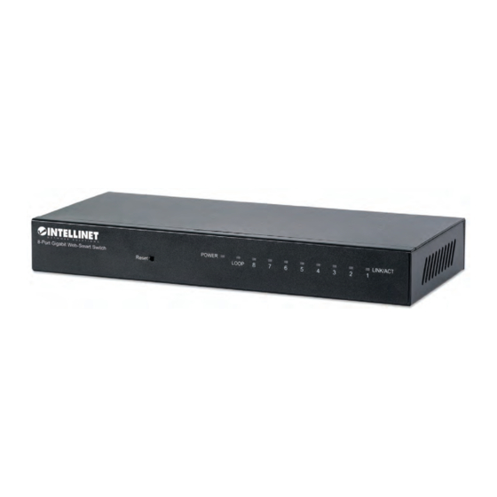
8‐Port Gigabit Web‐Smart Switch 2.3 The Front Panel LEDs Definition This device provides extensive LEDs to show the activities on power, system and ports. See the following description for your reference: LED Status Operation Steady Green The device is powered on. POWER Off ... -
Page 7: Hardware Installation
Media Speed Wiring 10Base‐T: UTP category 3, 4, 5 cable (maximum 100m) EIA/TIA‐568 10 Mbps 100Ω STP (maximum 100m) Network Media 100Base‐TX: UTP category 5, 5e cable (maximum 100m) EIA/TIA‐568 100 Mbps (Cable) 100Ω STP (maximum 100m) 1000Base‐T: UTP category 5e, 6 cable (maximum 100m) EIA/TIA‐568 1000 Mbps 100Ω STP (maximum 100m) 2.6 Connect to Web Admin Interface In order to configure the smart features of the Intellinet 8‐Port Gigabit Web‐Smart Switch, you need to set the IP address of your computer’s network adapter to a value of 192.168.2.xxx where xxx must not be equal to 1. Refer to Appendix A for details. The default IP of the Intellinet 8‐Port Gigabit Web‐Smart Switch is 192.168.2.1. Open “http://192.168.2.1” in your web browser. The login screen appears. User Name: ‘admin’ Password: ‘1234’ 7 | P a g e ... -
Page 8: System Configuration
8‐Port Gigabit Web‐Smart Switch 3 System Configuration 3.1 Management 3.1.1 Switch Information This page displays some core information about the Intellinet 8‐Port Gigabit Web‐Smart Switch. The information is read‐ only, except for the switch name, which you can edit. ... -
Page 9: Ip Address Settings
8‐Port Gigabit Web‐Smart Switch 3.1.2 IP Address Settings LABEL DESCRIPTION Enable or disable the DHCP Client function. If this is enabled, the Intellinet switch receives its IP settings (IP Address, DHCP Client Subnet Mask and Gateway) from a DHCP server in your LAN, i.e. a router. If set to ‘disable’, then you must provide the IP information yourself and enter them into the field below. IP Address System IP address of the switch. The default value 192.168.2.1. Subnet Mask Subnet mask of the switch. The default value is 255.255.255.0. Gateway ... - Page 10 8‐Port Gigabit Web‐Smart Switch Port Displays the port number. State Displays the actual state of the port. Speed/Duplex Config: Displays the configuration of link speed and duplex mode for the port. Actual: Displays the actual working state of the port. Flow Control Config: Displays the configuration of the flow control for the port. Actual: Displays the actual working state of the port. Note: The switch can’t be managed through a disabled port. Be sure not to disable the port through which you ...
-
Page 11: Trunk Group Settings
8‐Port Gigabit Web‐Smart Switch 3.1.4 Trunk Group Settings To create a link between the Intellinet 8‐Port Gigabit Web‐Smart Switch, you normally simply connect an RJ45 Ethernet cable to a port on a different switch. If that is also a Gigabit switch, this connection between the two switches would provide a bandwidth of 1 Gbps. In order to increase the bandwidth, you can set up a so called trunking group, which takes two physical ports and combines them to one logic port, doubling the bandwidth to 2 Gbps. 1. Select any two ports of ports one to four. 2. Click Add/Modify to create the trunk group ... -
Page 12: Eee - Energy Efficient Ethernet
8‐Port Gigabit Web‐Smart Switch 3.1.5 EEE – Energy Efficient Ethernet Energy‐Efficient Ethernet (EEE) is a set of enhancements to the twisted‐pair and backplane Ethernet family of computer networking standards that allow for less power consumption during periods of low data activity. The intention was to reduce power consumption by 50% or more, while retaining full compatibility with existing equipment. The Institute of Electrical and Electronics Engineers (IEEE), through the IEEE 802.3az task force developed the standard. EEE is a power saving option that reduces the power usage when there is low or no traffic utilization. EEE works by powering down circuits when there is no traffic. When a port is powered down for saving power, the outgoing traffic is stored in a buffer until the port is powered up again. Using this technique, more power can be saved if the traffic can be buffered up until a large burst of traffic can be transmitted. Keep in mind, that buffering traffic will add some latency in the traffic. ... -
Page 13: Maintenance
8‐Port Gigabit Web‐Smart Switch 3.2 Maintenance 3.2.1 User Account On this screen you can change the user name and password required to access the web administrator configuration menu. Enter a new username and password, then click Apply. You will then have to enter the new username and password in order to log back into the configuration. ... -
Page 14: Firmware Upgrade
If a new firmware needs to be installed, you can use this screen to do it. You can install a new firmware image (file) using TFTP, or HTTP. In order to begin the process, you must first enter the so‐called loader mode. After you click OK, you will see a new menu on the left side of the screen. This menu provides access to the TFTP and HTTP method of updating the firmware. TFTP To install the upgrade via TFTP, a TFTP server must be configured to accept connections from the Intellinet switch. Provide the IP address of the TFTP server along with the correct file name that you wish to install. Enter the Image File Name and click Download Image, then a message will pop up. 14 | P a g e ... - Page 15 8‐Port Gigabit Web‐Smart Switch Click OK and allow the procedure to complete. The switch will perform a restart at the end of the firmware upgrade procedure. HTTP In order to install the upgrade, select the appropriate upgrade type, then click on , select the file from your local HDD. Then press to begin. ...
-
Page 16: Config Backup And Restore
8‐Port Gigabit Web‐Smart Switch 3.2.3 Config Backup and Restore On this page you can save the entire configuration of the Intellinet 8‐Port Gigabit Web‐Smart Switch to a file, so you can re‐load (restore) it at a later time. Click on to begin. Then select and click . Then select the location where you wish to save the file, and click . ... -
Page 17: Reset To Default Config
8‐Port Gigabit Web‐Smart Switch 3.2.4 Reset to Default Config There are two ways to reset the Intellinet switch back to its factory default settings. Via Reset Button Press the reset button for at least 10 seconds while the switch is operation in order to trigger the factory default reset. Via Web Administrator Menu Click on , then provide administrator credentials and click ‘OK’ to begin. ... -
Page 18: Config Save
8‐Port Gigabit Web‐Smart Switch 3.2.5 Config Save In order to save any changes you make to the programming of the Intellinet Gigabit switch, you are going to have to click on . Once done, the message below confirms that all settings have been saved. 3.2.6 Reboot If you need to reboot the Intellinet switch from a remote location, this is the way to do it. When the reboot is triggered, the switch won’t be accessible and operational for about 60 seconds. ... -
Page 19: Multicast
8‐Port Gigabit Web‐Smart Switch 3.3 MultiCast 3.3.1 IGMP Snooping The Internet Group Management Protocol (IGMP) lets hosts and routers share information about multicast group memberships. IGMP snooping is a switch feature that monitors the exchange of IGMP messages and copies them to the CPU for future processing. The overall purpose of IGMP Snooping is to limit the forwarding of multicast frames to only ports that are a member of the multicast group. About the Internet Group Management Protocol (IGMP) Snooping Computers and network devices that want to receive multicast transmissions need to inform nearby routers that they will become members of a multicast group. The Internet Group Management Protocol (IGMP) is used to communicate this information. IGMP is also used to periodically check the multicast group for members that are no longer active. In the case where there is more than one multicast router on a sub network, one router is elected as the ‘queried’. This router then keeps track of the membership of the multicast groups that have active members. The information received from IGMP is then used to ... -
Page 20: Monitoring
8‐Port Gigabit Web‐Smart Switch 4 Monitoring 4.1 Port Statistics These pages provides statistical data about the network ports of the Intellinet switch. LABEL DESCRIPTION Port ... -
Page 21: Diagnostic
8‐Port Gigabit Web‐Smart Switch 4.2 Diagnostic With this page it is possible to test all connected cables. The following table describes the labels in this screen. LABEL DESCRIPTION Check Click the checkbox to select the port to be diagnosed. Port Displays the port number of the switch. Test Result Open: The cable is broken or no cable connection. ... -
Page 22: Port Mirroring
8‐Port Gigabit Web‐Smart Switch 4.3 Port Mirroring Network engineers or administrators use port mirroring to analyze and debug data or diagnose errors on a network. It helps administrators keep a close eye on network performance and alerts them when problems occur. It can be used to mirror either inbound or outbound traffic (or both) on single or multiple interfaces. Port mirroring is used on a network switch to send a copy of network packets seen on one switch port (or an entire VLAN) to a network monitoring connection on another switch port. The following table describes the labels in this screen. LABEL DESCRIPTION Mirror Direction ... -
Page 23: Vlan
8‐Port Gigabit Web‐Smart Switch 5 VLAN A Virtual Local Area Network (VLAN) is a network topology configured according to a logical scheme rather than the physical layout. VLAN can be used to combine any collection of LAN segments into an autonomous user group that appears as a single LAN. VLAN also logically segments the network into different broadcast domains so that packets are forwarded only between ports within the VLAN. Typically, a VLAN corresponds to a particular subnet, although not necessarily. VLAN can enhance performance by conserving bandwidth, and improve security by limiting traffic to specific domains. A VLAN is a collection of end nodes grouped by logic instead of physical location. End nodes that frequently communicate with each other are assigned to the same VLAN, regardless of where they are physically on the network. Logically, a VLAN can be equated to a broadcast domain, because broadcast packets are forwarded to only members of the VLAN on which the broadcast was initiated. The Intellinet 8‐Port Gigabit Web‐Smart Switch supports three types of VLANs. Port‐based VLANs Port‐based VLAN limits traffic that flows into and out of switch ports. Thus, all devices connected to a port are members of the VLAN(s) the port belongs to, whether there is a single computer directly connected to a switch, or an entire department. On port‐based VLANs, NICs do not need to be able to identify 802.1Q tags in packet headers. NICs send and receive normal Ethernet packets. If the packet's destination lies on the same segment, communications take place using normal Ethernet protocols. Even though this is always the case, when the destination for a packet lies on another switch port, VLAN considerations come into play to decide if the packet is dropped by the Switch or delivered. IEEE 802.1Q VLANs ... -
Page 24: Vlan Mode Setting
8‐Port Gigabit Web‐Smart Switch MTU multi‐tenant unit VLAN This is a one‐click solution which generates a VLAN setup where one port is accessible from all other ports, but the other seven ports are isolated from one another. A possible application could be an apartment building where up to 7 families share an Internet connection. The Internet Router or Gateway is connected to port 1 whereas the other 7 families are connected to ports 2 – 8. 5.1 VLAN Mode Setting Select the VLAN mode you wish to use. 5.2 Port Based VLAN ... - Page 25 8‐Port Gigabit Web‐Smart Switch The following table describes the related labels in this screen. LABEL DESCRIPTION VLAN ID Enter the ID number of VLAN. VLAN Name Optional name for the VLAN. Port Displays the port number of the switch Select All Click to quickly select all ports at once. Not Member Port(s) not member(s) of the VLAN group. ...
-
Page 26: Mtu Vlan
8‐Port Gigabit Web‐Smart Switch 5.3 MTU VLAN If the VLAN mode MTU is activated, you can configure the settings on this page. There isn’t really much to do except for clicking the apply button. That’s because MTU VLAN by default isolates ports 2 – 8 and only allows access to the shared port 1. Once you click , the new settings will show on the configuration screen: Notice how port 1 is shared among all other ports. In this setup for example, port 8 can communicate with port 1, but not with ports 2 – 7. ... -
Page 27: 802.1Q Vlan
8‐Port Gigabit Web‐Smart Switch 5.4 802.1Q VLAN Allows you to create virtual networks using 802.1Q. When using 802.1Q VLAN, you configure ports to be a part of a VLAN group. When a port receives data tagged for a specific VLAN group, the data is discarded unless the port is a member of the VLAN group. This technique is useful for communicating with devices outside of your local network as well as still receiving data from other ports not in your VLAN group. It requires that you know the VLAN group IDs used. 5.4.1 802.1Q Static VLAN On this page the user can configure the 802.1Q Static VLAN feature and the related settings. LABEL DESCRIPTION ... -
Page 28: 802.1Q Vlan Port
8‐Port Gigabit Web‐Smart Switch LABEL DESCRIPTION VLAN ID Displays the ID number of the VLAN. VLAN Name Displays the name of the VLAN. Member Ports Displays the member ports of the VLAN. Tagged Ports Displays the tagged member ports of the VLAN. Untagged Ports ... - Page 29 8‐Port Gigabit Web‐Smart Switch The following table describes the labels in this screen. LABEL DESCRIPTION Port Select the port(s) you wish to configure. PVID PVID number for the ports. It can range from 1 to 4094. When adding the tag header to the received untagged packet, the switch will automatically use this PVID value as the VLAN ID of the added tag. Accepted Frame Type Select All/Tag‐only/Untag‐only from the drop‐down list. ...
-
Page 30: Qos
8‐Port Gigabit Web‐Smart Switch 6 QoS Quality of Service (QoS) is an advanced traffic prioritization feature that allows you to establish control over network traffic. QoS enables you to assign various grades of network service to different types of traffic, such as multi‐media, video, protocol‐specific, time critical, and file‐backup traffic. QoS reduces bandwidth limitations, delay, loss, and jitter. It also provides increased reliability for delivery of your data and allows you to prioritize certain applications across your network. You can define exactly how you want the switch to treat selected applications and types of traffic. You can use QoS on your system to control a wide variety of network traffic by: Classifying traffic based on packet attributes. Assigning priorities to traffic (for example, to set higher priorities to time‐critical or business‐ critical applications). ... - Page 31 8‐Port Gigabit Web‐Smart Switch Example Setup The example above could be used on the following scenario: 1. A Voice over IP phone is connected to port 8. It has the highest priority. 2. A media streaming device such as a smart TV, FireTV, Android TV box, Apple TV or Kodi, is connected to port 7. Only VoIP traffic for port 8 has higher priority. 3. All other devices have the lowest priority. ...
-
Page 32: Bandwidth Control
8‐Port Gigabit Web‐Smart Switch 6.2 Bandwidth Control Policing, or rate limiting, allows you to limit the data rates for a particular port on the Intellinet 8‐Port Gigabit Web‐Smart Switch. When the data rate exceeds user‐configured values, the Intellinet switch drops packets immediately. Rate limiting is configured for two types of transmissions, which are ingress and egress. Ingress traffic is received on any given port (incoming, inbound or download), whereas egress traffic is traffic sent out (outgoing, outbound or upload) to another network client. The following table describes the labels in this screen. LABEL ... -
Page 33: Security
8‐Port Gigabit Web‐Smart Switch 7 Security 7.1 Storm Filter The Storm Filter function enables the Intellinet switch to filter broadcast, multicast, unknown unicast and multicast frames in your network. If the transmission rate of these kinds of packets exceeds the set bandwidth, the packets will be automatically discarded to avoid network broadcast storm. Select the Storm Type from the drop‐down list. Hold “Ctrl” and the left button of the mouse to select the ports you need, select Enable from the State drop‐down box to enable the setting, and then choose the rate from the checkbox. Click Apply, then the Storm Filter information will be displayed as below. ... -
Page 34: Loop Prevention
8‐Port Gigabit Web‐Smart Switch 7.2 Loop Prevention The Intellinet 8‐Port Gigabit Web‐Smart Switch can detect loops in your network. The loop detection feature is designed to detect loopbacks and activate the Loop LED on the front panel of the switch. Loop detection also indicates the port(s) causing the loop on the web administrator UI. The loop prevention feature, on the other hand, blocks any port that has been deemed to be causing a loop automatically. Select the type of loop detection/prevention mechanism from the drop‐down list, then click ‘Apply.’ ... -
Page 35: Dhcp Snooping
8‐Port Gigabit Web‐Smart Switch 7.3 DHCP Snooping The addresses assigned to DHCP clients on unsecure ports can be carefully controlled using the dynamic bindings registered with DHCP Snooping. DHCP Snooping allows the Intellinet switch to protect a network from rogue DHCP servers or other devices which send port‐related information to a DHCP server. This information can be useful in tracking an IP address back to a physical port. Command Usage Network traffic may be disrupted when malicious DHCP messages are received from an outside source. DHCP Snooping is used to filter DHCP messages received on a non‐secure interface from outside the network or firewall. ... -
Page 36: Appendix A: Changing The Ip Address Of A Network Adapter
8‐Port Gigabit Web‐Smart Switch 8 Appendix A: Changing the IP Address of a Network Adapter The Intellinet 8‐Port Gigabit Web‐Smart Switch operates on the IP address 192.168.2.1. For your computer to access the administrator configuration interface, the IP address of the network adapter in your computer has to be in the same range; e.g., 192.168.2.50. Refer to the instructions that came with your computer for information on how to change the IP address on the network adapter in your computer for any operating system that is not explained in this user manual. 8.1 Windows 8 1. If you are using a PC, move the mouse cursor to the bottom or top right corner of the screen and select the cog icon for Settings. If you are using a tablet, swipe left from the right side of the screen and select Settings. ... - Page 37 8‐Port Gigabit Web‐Smart Switch 4. Open “Network and Sharing Center.” 5. Click “Change adapter settings.” 6. Right‐click your network adapter and select “Properties.” 7. Select “Internet Protocol Version 4” from the list and click “Properties.” 37 | P a g e ...
- Page 38 8‐Port Gigabit Web‐Smart Switch 8. Enter the information as shown below, then click “OK” to save the settings. 38 | P a g e ...
-
Page 39: Windows 7 And 10
8‐Port Gigabit Web‐Smart Switch 8.2 Windows 7 and 10 1. Open the Network and Sharing Center. 2. Click on “Change adapter settings.” 3. Right‐click your network adapter and select “Properties.” 4. Select “Internet Protocol Version 4” from the list and click “Properties.” 5. Enter the information as shown below, then click “OK” to save the settings. ... -
Page 40: Windows Xp
8‐Port Gigabit Web‐Smart Switch 8.3 Windows XP: 1. Double‐click the “Network Connections” icon in the control panel. 2. Right‐click the connection (e.g., Local Area Connection) and select “Properties.” 3. Select “Internet Protocol (TCP/IP)” from the list and click “Properties.” 4. Enter the information as shown below, then click “OK” to save the settings. ... -
Page 41: Mac Os X
8‐Port Gigabit Web‐Smart Switch 8.4 Mac OS X 1. Open the System Preferences page. 2. In the Internet & Network section, click the Network icon. 3. Select either Built‐in Ethernet or AirPort, depending on how you connect to the wireless access point, then click “Configure… .” 4. Set the value for Configure IPv4 to “Manually” and enter 192.168.2.50 in the IP Address field. Click “Apply Now” (not shown in screen shot) to save the settings. ... -
Page 42: Warranty
8‐Port Gigabit Web‐Smart Switch 9 Warranty Deutsch Garantieinformationen finden Sie hier unter intellinetnetwork.com/warranty. English For warranty information, go to intellinetnetwork.com/warranty. Español Si desea obtener información sobre la garantía, visite intellinetnetwork.com/warranty. Français Pour consulter les informations sur la garantie, rendezvous à l’adresse intellinetnetwork.com/warranty. Italiano Per informazioni sulla garanzia, accedere a intellinetnetwork.com/warranty. Polski Informacje dotyczące gwarancji znajdują się na stronie intellinetnetwork.com/warranty. México Póliza de Garantía Intellinet — Datos del importador y responsable ante el consumidor IC Intracom México, S.A.P.I. de C.V. • Av. Interceptor Poniente # 73, Col. Parque Industrial La Joya, Cuautitlan Izcalli, Estado de México, C.P. 54730, México. • Tel. (55)1500‐4500 La presente garantía cubre los siguientes productos contra cualquier defecto de fabricación en sus materiales y mano de obra. A. Garantizamos cámaras IP y productos con partes móviles por 3 años. B. Garantizamos los demás productos por 5 años (productos sin partes móviles), bajo las siguientes condiciones: 1. Todos los productos a que se refiere esta garantía, ampara su cambio físico, sin ningún cargo para el consumidor. 2. El comercializador no tiene talleres de servicio, debido a que los productos que se garantizan no cuentan con reparaciones, ni refacciones, ya que su garantía es de cambio físico. 3. La garantía cubre exclusivamente aquellas partes, equipos o sub‐ensambles que hayan sido instaladas de fábrica y no incluye en ningún caso el equipo adicional o cualesquiera que hayan sido adicionados al ... -
Page 43: Copyright
8‐Port Gigabit Web‐Smart Switch 10 Copyright Copyright ©2016 IC Intracom. All rights reserved. No part of this publication may be reproduced, transmitted, transcribed, stored in a retrieval system, or translated into any language or computer language, in any form or by any means, electronic, mechanical, magnetic, optical, chemical, manual or otherwise, without the prior written permission of this company This company makes no representations or warranties, either expressed or implied, with respect to the contents hereof and specifically disclaims any warranties, merchantability or fitness for any particular purpose. Any software described in this manual is sold or licensed "as is". Should the programs prove defective following their purchase, the buyer (and not this company, its distributor, or its dealer) assumes the entire cost of all necessary servicing, repair, and any incidental or consequential damages resulting from any defect in the software. Further, this company reserves the right to revise this publication and to make changes from time to time in the contents thereof without obligation to notify any person of such revision or changes. -
Page 44: Federal Communication Commission Interference Statement
8‐Port Gigabit Web‐Smart Switch 11 Federal Communication Commission Interference Statement This equipment has been tested and found to comply with the limits for a Class B digital device, pursuant to Part 15 of FCC Rules. These limits are designed to provide reasonable protection against harmful interference in a residential installation. This equipment generates, uses, and can radiate radio frequency energy and, if not installed and used in accordance with the instructions, may cause harmful interference to radio communications. However, there is no guarantee that interference will not occur in a particular installation. If this equipment does cause harmful interference to radio or television reception, which can be determined by turning the equipment off and on, the user is encouraged to try to correct the interference by one or more of the following measures: 1. Reorient or relocate the receiving antenna. 2. Increase the separation between the equipment and receiver. 3. Connect the equipment into an outlet on a circuit different from that to which the receiver is connected. ... - Page 45 Intellinetnetwork.com © IC Intracom. All rights reserved. Intellinet is a trademark of IC Intracom, registered in the U.S. and other countries. 45 | P a g e ...
Need help?
Do you have a question about the 561099 and is the answer not in the manual?
Questions and answers