LSI GS550 Master User Manual
System, includes the cabin mounted radio display and compatible crane mounted sensors
Hide thumbs
Also See for GS550:
- User manual (89 pages) ,
- Installer and user manual (64 pages) ,
- Quick reference manual (2 pages)

Related Manuals for LSI GS550


Summary of Contents for LSI GS550
- Page 1 Master User's Manual The GS550 System Document Part Number GM550, Version 2004, Revision B 12500 R:24.2 27000 Jib 30ft Engineered weighing solutions for crane and lifting application...
- Page 3 2.5.1 System Sensors Diagnostic ................21 2.5.2 Radio Network Diagnostic..................22 2.5.3 Lockout Diagnostic....................22 2.5.4 Display Diagnostic ....................23 2.5.5 Digital Input Diagnostic..................23 2.5.6 Password Settings ....................23 2.5.7 Angle Calibration Procedure № 1: Mechanical Set-Up ........24 2.5.8 Angle Calibration Procedure № 2: Correct with the GS550........24...
- Page 4 2.5.9 Boom Length Calibration Procedure № 1: Mechanical Set-Up......25 2.5.10 Boom Length Calibration Procedure № 2: Correct with the GS550 ....26 2.6 Radius ........................28 2.6.1 Radius Verification and Adjustment ..............28 2.6.2 Radius Settings ....................29 2.6.3 Basic Radius Parameters for a Lattice Crane............31 2.6.4 Basic Radius Parameters for a Telescopic Boom Crane ........32...
- Page 5 3.2.4 Transfer Data Logger Files from the GS550 to the PDA........53 3.2.5 Transfer Data Logger Files from the PDA to a Personal Computer .......53 3.3 Trouble Shooting PDA Communication Issues ............55 3.4 Data Logger Viewer....................56 3.4.1 Installation on a Personal Computer ..............56 3.4.2 Quick Start .......................56...
- Page 6 Figure 22 Rope Payout Calibration....................42 Figure 23 Alternative Installation....................43 Figure 24 Menu Page 4A1) Sensor List..................46 Figure 25 Menu Page 4A) Sensor List................... 46 Figure 26 Transfer Firmware Updates And Rated Capacity Charts To The GS550 ...... 50 The GS550 System...
- Page 7 Figure 29 Palm HotSync Page .......................52 Figure 30 Palm LSI Firmware List ....................52 Figure 31 A) Palm LSI Datalogger File List; B) Palm LSI Datalogger Options .......53 Figure 32 Send To Menu........................55 Figure 33 Two User Name Example On The Same PC ..............55 Figure 34 Datalogger Viewer System.....................56...
- Page 8 Table 1 Information Menu Alerts....................15 Table 2 Weight Units........................20 Table 3 Full report column headings....................57 Table 4 Wind report column headings ................... 58 Table 5 Model Numbers......................... 59 Table 6 Equipment Marking ......................63 The GS550 System...
- Page 9 CE and ATEX Certifications Master User's Manual Convention For information on CE and ATEX Certifications, please refer to sections relative on certification Warning means that there is a possible and declaration of conformity. danger. This action should be performed in order to meet the proper operation, and it is performed not to break the system.
- Page 10 The GS550 System...
-
Page 11: Introduction
GC series load cells and GS001 series line rider and load pin transmitters, the GS010 angle sensors, the GS011 angle sensor and length transmitter and the GS020 wind speed sensor. The GS550 system is designed as an operator aide and is in no way a substitute for safe operating practice 1.2 Version Compatibility (applies for produced manufactured prior to... -
Page 12: Figure 1 Key Components In A Typical System
Figure 1 Key Components In A Typical System The GS550 System... -
Page 13: Operation
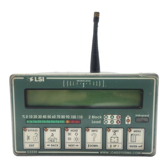
2. Operation 2.1 Display GS550 The GS550 displays detailed information on the backlit, two lines liquid crystal display (LCD) (see Figures 2 and 3). Additional information including warnings, alarms, and radio status is communi- cated by the display lights and the display buzzer. -
Page 14: Liquid Crystal Display
GT103 portable download tool or other compatible device. 2.1.4 Keypad The keypad consists of six buttons used to control, consult, program, and troubleshoot the GS550 display and system. Each button has two functions; a primary function for the operation display, and a secondary function for menu navigation and programming. - Page 15 Systems with more than one load sen- sor typically display main hoist load information on the first page and auxiliary hoist load information on the second page. This applies only if the GS550 has been correctly installed to control crane lockout function. 2. Operation...
- Page 16 If the lockout relay is inverted this alert will occur when voltage is detected on the wire when safe. † If the lockout relay is inverted this alert will occur when voltage is not detected on the wire in alarm. The GS550 System...
-
Page 17: Menu System
2) Crane Rigging 3) Display Settings 4) Installation 5) System Diagnostic 2.2 Menu System There are five basic menus (level one) used to program, consult and control the GS550 system. 1) Parts of Lines 2) Crane Rigging 3) Display Settings 4) Installation 5) System Diagnostic 2. -
Page 18: Menu Numbers
1. Most menus are circular; press Next on the last page of a menu to return to the first page. 2. Most lists are circular; press Down on the last entry of a list to return to the first entry. The GS550 System... -
Page 19: Password Protection
AZA. If the user password is forgotten, it can be changed as long as the administrator pass- word is known. Forgotten password? Call LSI technical support (Houston, TX) at 888 819 4355 or contact your local LSI representative. 2.2.4 Menu Layout Figure 6 shows the menus accessible to the operator without password protection under the default factory settings. -
Page 20: Parts Of Line
2.3 Rated Capacity Indicators The GS550 can be programmed to assist the operator by indicating the working load limit (WLL) from the crane specific rated capacity charts according to the angle and radius information re- ceived from the boom mounted sensors. -
Page 21: Display Programming
Rated capacity indication is based on interpretation of a selected capacity chart using boom angle and load radius. The chart must be selected by “rigging” the working hoist in the GS550; this is done by following the chart wizard in menu 2) Crane Rigging. -
Page 22: Display Settings
Metre (m) Table 2 Weight Units 2.4.2 Language Future versions of the GS550 will include different display language options. 5. Press Menu, and then Next twice. 6. Press Enter, and then Next twice to go to menu 3B) Display language. -
Page 23: Light Intensity
2.4.3 Light Intensity Adjust the intensity off the LEDs (light emitting diodes) to facilitate viewing in bright sunlight or in reduced visibility. 8. Press Menu, and then Next twice. 1. Press Enter, and then Next twice to go to menu 3C) Light intensity adjustment. 2. -
Page 24: Radio Network Diagnostic
Warning! The "list of last 32 sensors received" includes all functioning GS series sensors within range. Programming a GS550 display for sensors from a different system will disable that system and render indication by both systems inaccurate. 3. Press Next to go to menu 5B2) List last 32 sensors received. -
Page 25: Display Diagnostic
4. Press Next to go to menu 5D4) Display internal temperature. 5. Press Next to go to menu 5D5) GS550 base station id. The base station id should be the same as the GS550 display serial number printed on the left side of the box 6. -
Page 26: Angle Calibration Procedure № 1: Mechanical Set-Up
When the angle sensor is moved very slowly, it may take several seconds to see an update at the GS550 display. Instead move the sensor up a couple of degrees, and then bring it back down to where it should be. The small light on the angle sensor flashes when it transmits a new value to the display. -
Page 27: Boom Length Calibration Procedure № 1: Mechanical Set-Up
Operation Display 1) Parts of Line 2) Crane Rigging 3) Display Settings 4) Installation 4A) Sensor List 4B) Sensor Calibration Enter user password: 4B1) Automatic value 4B2) Manual parameter calibration wizard calibration 4B2A) No. x id: Gxxxxx 4B2A) No. x id: Gxxxxx Load sensor Angle sensor Heartbeat 60... -
Page 28: Boom Length Calibration Procedure № 2: Correct With The Gs550
If not then follow 2.5.10 Boom Length Calibration Procedure № 2: Correct with the GS550. 2.5.10 Boom Length Calibration Procedure № 2: Correct with the GS550 If the displayed boom length does not match the actual length of the boom retracted or extended and if it is not possible to easily correct by following Boom Length Calibration Procedure №... - Page 29 2. Press Enter and Next to go to menu 4B) Sensor Calibration. 3. Press Enter to go to the password page. 4. Use Back, Next, Up, and Down to enter the user password, and then press Enter to go to 4B1) Automatic Value Calibration Wizard.
-
Page 30: Radius
Repeat until the radius displayed equals the actual radius. When the hoist is rigged off a luffing jib only † Telescopic boom cranes only ‡ Systems with rated capacity charts programmed in the GS550 only The GS550 System... -
Page 31: Radius Settings
With the boom at 45° and the maximum load on the hoist, the boom deflection value should equal the difference between the actual and the displayed radius. With the boom at 45° and half the maximum load on the hoist, the boom deflection value should equal twice the difference between the actual and the displayed radius. -
Page 32: Figure 13 Radius Settings
4C16) Manual length 4C6) Boom top offset 4C17) Sheave head len. perpendicular 4C7) No load Deflection 4C18) Sheave head len. parallel 4C8) Jib offset 4C19) Sheave radius 4C9) Lattice extension offset 4C20) Deduct Figure 13 Radius Settings The GS550 System... -
Page 33: Basic Radius Parameters For A Lattice Crane
2.6.3 Basic Radius Parameters for a Lattice Crane Jib mounting point Jib offset angle Head sheave Sheave radius (menu 4C19) Jib length (Your measurement) Sheave head length perpendicular (menu 4C17) The distance from the head sheave centre to the boom centreline (Your measurement) Boom Length (menu 4C1) The distance from the... -
Page 34: Basic Radius Parameters For A Telescopic Boom Crane
• If the boom base pin is behind the centre Crane centre of rotation of rotation this value will be negative. (Your measurement) Figure 15 Basic Radius Parameters For A Telescopic Boom Crane The GS550 System... -
Page 35: Advanced Radius Parameters
2.6.5 Advanced Radius Parameters Typical sheave heads: Extensions, two possibilities: 1) Manual length (4C16): The offset is • 4C17) Sheave head length perpendicular = always zero degrees. 2) Lattice extension length(4C15): • 4C18) Sheave head length parallel = 0 The offset angle must be adjusted. Special top sheaves (example: rooster): 4C15) Lattice extension... -
Page 36: Load Pin Transmitter Gs001
The transmitter antenna must not be in contact with any metal object. Warning! Do not weld in proximity to LSI sensor/transmitters. 2. Weld the mounting blocks where required. 3. Mount the load pin transmitter on the mounting blocks. -
Page 37: Four Point Lift
1. Press Menu, and then Next three times to go to menu 4) Installation (see Figure 17). 2. Press Enter and Next to go to menu 4B) Sensor Calibration. 3. Press Enter to go to the password page. 4. Use Back, Next, Up, and Down to enter the user password, and then press Enter to go to 4B1) Automatic Value Calibration Wizard. -
Page 38: Sum Load Indication
• Slack Rope These functions can be used to generate an alarm condition on the lockout wires of the GS550. 2.8.1 Sum Load Indication When sum load indication is programmed the sum of the loads on the pre-determined load sensors is indicated by the operation display. -
Page 39: Slack Rope
2. Press Enter twice to go to the sensor list (4A1). 3. Press Next repeatedly to advance to the next available sensor position, usually follow- ing the four load sensors and the sum load sensor. 4. The id can be left at 0, press Next. 5. -
Page 40: List And Trim Angle Sensor
List (roll) Trim (pitch) Figure 18 List And Trim Axes 2.9.1 Programming the GS550 for List and Trim Indication For list indication, add the GS010-03 id number to the sensor list (menu 4A1) and select the sensor type “List sensor”. -
Page 41: Mounting Instructions
3. Mount the angle sensor to the weld pads with the screws and washers provided. 4. Verify list and trim angle indication by the GS550 (see Figure 19); in operation display, use Next to advance to the list and trim indication page. -
Page 42: Figure 20 Trim Angle Calibration
12. Repeat steps 6 through 11 for the list angle. 13. Press Exit four times to return to the operation display. 14. Verify accurate list and trim angle indication (see Figure 20). Figure 20 Trim Angle Calibration The GS550 System... -
Page 43: Rope Payout
Alternatively the rope payout sensor may be installed on an appropriate sheave. Power supply must be provided to the rope payout sensor. A GS550 display can then be programmed to com- municate with the sensor and to indicate rope payout (length) and rope speed. -
Page 44: Rope Payout Calibration Procedure № 2: Correct With The Gs550
5. Verify the rope payout indicated matches the actual length of wire rope paid out. If not then follow Rope Payout Calibration Procedure № 2. 2.10.3 Rope Payout Calibration Procedure № 2: Correct with the GS550 If rope payout indicated does not match actual rope payout, and if it is not possible to easily correct by following Rope Payout Calibration Procedure №... -
Page 45: Rope Payout Limits
Figure 23 Alternative Installation 2.11 Data Logger The GS550 includes a data logger that records all significant events including actual sensor values and a date and time stamp. The data logger memory can hold over 16 000 records, this is equiva- lent to several days or several years of operation depending on the recording mode selected and machine use. -
Page 46: Recording Modes
User input. Available on request only, the status of all sensors is recorded on demand. A custom hardware modification to the GS550 display is required and a normally open push button must be installed on a digital input to the GS550 through a pre-determined wire of the power supply and lockout cable. -
Page 47: The Sensor List
All sensors in the GS550 system are programmed in the sensor list. The GS550 uses information from all sensors in the sensor list. Conversely the GS550 will not use or display information from sensors that are not programmed to the sensor list. If a sensor is removed from the crane then it must be removed from the sensor list. -
Page 48: How To Remove A Sensor From The Gs550
8. Press Enter to save any changes made to the sensor list. 9. Press Exit three times to return to the operation display. 2.12.2 How to Remove a Sensor from the GS550 1. Determine the sensor to be removed. If more than one sensor of the same type has been added to the sensor list then determine the radio identification number (id) of the sensor to be removed before proceeding. -
Page 49: Network Options
2.13 Network Options 2.13.1 Listen Only Mode When the GS550 is started it normally wakes up the sensors in the sensor list and takes control of them. The last display started that is programmed for a sensor becomes that sensor’s network controller. -
Page 50: Repeater
2.13.2 Repeater Communication between a GS550 and a programmed sensor can be routed through a different programmed sensor (repeater). This can be done either to extend the range of the network or to assist communication around a large radio obstacle. The battery life of the sensor repeated (source) will be reduced by about a year . -
Page 51: Wireless Sensor Update
2.13.3 Wireless Sensor Update It is possible to send a firmware update to a sensor using the GS550 (menu 4I4). For more infor- mation on installing a sensor update refer to the field service guide How to Update the Firmware of a GS Series System (document part number GM550 011) provided with the firmware update kit. -
Page 52: Portable Download Tool
Update firmware, install rated capacity charts or export data logger files using the portable download tool without removing the display from the crane. The PDA and the GS550 display connect wirelessly through the IrDA (infrared) ports and the PDA and a personal computer (PC) can be connected with a USB cable (see Figures 26 and 27). -
Page 53: Installing Pda Software
3.2.1 Transfer Firmware Files from a Personal Computer to the PDA Two types of files can be sent to the PDA: • LSI files identified by the filename extension .pdb, including firmware, rated capacity charts and system configuration updates for the GS550. •... -
Page 54: Transfer Firmware Files From The Pda To A Gs550
Press the house icon to go to the Home menu. b. Select the LSI Firmware icon from the Home menu. 2. On the GS550 display, press and hold Bypass while starting the display. The display will enter a safer mode and allow firmware updates. -
Page 55: Conserve Gs550 Configuration When Updating Firmware
Select All from the drop down menu in the upper right hand corner c. Select LSI Datalogger. 2. Align the infrared ports of the PDA and the GS550 about 6 inches (10 centimetres) apart. 3. On the PDA, receive the file: a. - Page 56 2. On the PDA, press the star icon to start HotSync. HotSync will connect the PDA with the PC and update files from each. Data logger files will be transferred to the following directory of the personal computer: C:\Program Files\Palm\PALM_NAME\Backup Note: PALM_NAME is the actual name of the PDA device. The GS550 System...
-
Page 57: Trouble Shooting Pda Communication Issues
PDA. Example: 1.1M means 1.1 megabytes, equates to 1100 kb (kilobytes). Each GS550 firm- ware uses more than 140 kb of memory. If there is not enough memory left, verify if some applications or data logger files could be removed. -
Page 58: Data Logger Viewer
The Datalogger Viewer (see Figure 34) is a software application used to display on a personal computer (PC) a log file generated by the GS550 data logger. To transfer data logger files from a GS550 to a PC see the section “Transferring Files”. -
Page 59: Full Report
C:\Program Files\PDA\PDA_NAME\Backup\ Note: PDA_NAME is the actual name given to the PDA. 4. Select the log file to open. Only .pdb files generated by the LSI software in the Portable Download Tool are supported. Example: A typical file name for a log file generated by a GS550 data logger LSI_08_13_2004_15_31_48.PDB... -
Page 60: Figure 36 Exerpt Of Wind Report
Wind charts. The data from the Wind or Max Gust columns can be easily charted (see Figure 37). Figure 37 Maximum Gust Chart 1. Press Control and select the time column and either the Wind or the Max Gust column. 2. Click Insert, and then Chart. 3. Select X-Y (Scatter) The GS550 System... -
Page 61: Certification Notes
GS010-01-CE GS010-01-ATEX-CE GS010-02 GS010-02-CE GS010-02-ATEX-CE GS010-03 GS010-03-CE GS010-03-ATEX-CE GS011 GS011-CE GS011-ATEX-CE GS020 GS020-CE GS020-ATEX-CE GS050 GS050-CE GS050-ATEX-CE GS550 GS550-CE GS550-ATEX-CE GS550-03 GS550-07 GS550-07-CE GS550-07-ATEX-CE GS550-08 GS550-08-CE GS550-08-ATEX-CE GS550-09 GS550-09-CE GS550-09-ATEX-CE GS550-10 GS550-10-CE GS550-10-ATEX-CE Table 5 Model Numbers CSA and ATEX CSA Class I, Division 1 and 2 Rated Equipment: part numbers end with “–CSA”... -
Page 62: Important Notes For Hazardous Area Certified Components
Here is one table that specifies which type of battery should be used for a particular component or component model. Please follow this table and each specification recommended. Models Battery Par Number Manufacturer Voltage Temperature Type Per Cell Code GC005-ATEX-CE TL-5930 Tadiran 3.6V GC012-ATEX-CE GC018-ATEX-CE GC035-ATEX-CE GC060-ATEX-CE GC100-ATEX-CE GC170-ATEX-CE The GS550 System... -
Page 63: Ensuring Safe Operation In Hazardous Areas
A description of display status and warning lights is available in the Operation chapter, page 10 of this manual. 4.4 Product Repair And Servicing LSI products have no replaceable or user’s serviceable parts, except the antenna (Installation Manual, page 10) and the batteries (Installation Manual, page 42). Suggested maintenance instructions of load cells are described on page 14 of the Installation Manual. -
Page 64: Equipment Marking
GCxxx GS001 GS002 GS005 GS010 GS020 Model №:GC012-ATEX-CE Load Systems Load Cell 5.4 t (12 000 lb) International Single part line pull capacity Please read the user’s manual for details II 1 G Ex ia IIC T4 The GS550 System... -
Page 65: Table 6 Equipment Marking
GS020 Intrinsically, safe sensors have the following stainless steel plate: part number UB223: Table 6 Equipment Marking 4. Certification Notes... -
Page 66: Gs550 Display Labels
4.6 GS550 Display Labels Figure 38 GS550 Display Labels Label CSA Class 1 Div 2 ATEX UB227 UB227 Label UB227 Label Do not connect the system UB217 Label UB217 Label Do notdisconnect the system unless this is a UB226 Label... -
Page 67: Certifications Used For Class 1 Division 1 And Division 2
4.7 Certifications Used For Class 1 Division 1 And Division 2 Class 1, Division 1 certification (intrinsically safe) is available for most LSI sensors. Class 1, Division 2 certification (non-incendiary) is available for the GS550 display. Certificate CSA #1332949 on master contract 215780 is available on request. - Page 68 The required antenna impedance is 50 ohms. To reduce potential radio interference to other users, the antenna type and its gain should be so chosen that the equivalent isotropically radiated power (e.i.r.p.) is not more than that permitted for successful communication. The GS550 System...
-
Page 69: Emi / Emc
SAE J159 and SAE J987 • ASME B30.5-2000 • Franklin laboratory: LSI products are safe to use in proximity to blasting caps • New-York City: MEA 110-05-E, in compliance with 19.1.1(a).1 requirements of Reference Standard RS 19-2 of the Building Code •... -
Page 70: Ce – Declaration Of Conformity
4.13 CE – Declaration of Conformity The GS550 System... -
Page 71: Figure 39 Gc005 Wireless Load Cell
Datasheets: The following figures show all sensors, load cells and display available including the temperature and humidity levels. In addition, it is to mention that the ingress protection (IP) of equipment corresponds to 65. The ingress protection of equipment is an "international classification system for sealing effectiveness of enclosures". -
Page 72: Figure 40 Gc012 Wireless Load Cell
Figure 40 GC012 Wireless Load Cell Figure 41 GC018 Wireless Load Cell The GS550 System... -
Page 73: Figure 42 Gc060 Wireless Load Cell
Figure 42 GC060 Wireless Load Cell Figure 43 GC100 Wireless Load Cell 4. Certification Notes... -
Page 74: Figure 44 Gc170 Wireless Load Cell
Figure 44 GC170 Wireless Load Cell Figure 45 GS020 Wind Speed Sensor The GS550 System... -
Page 75: Figure 46 Gs050 A2B Switch
Figure 46 GS050 A2B Switch Figure 47 GS550 Wireless Display Environmental Conditions: Operating temperature: -35º C to 85º C (-31º F to 185º F) Humidity range: 0% to 100% for all components except for GS020 Wind Speed Sensor, that is 10% to 100%... - Page 76 12. When there are bushings, grease them before the re-installation. 13. Grease the two holes. Important! • In some cases, the antenna may be replaced. To know how to replace and clean it, refer to section Replacing A Sensor Antenna of the Maintenance Manual. The GS550 System...
-
Page 77: Gs550 Menu Outline
5. GS550 Menu Outline 4D9) Radius tolerance 1) Parts of Line 4D10) Boom angle tolerance 4E) Memory Banks 2) Crane Rigging 4E1) Copy configuration to memory bank A 4E2) Copy configuration to memory bank B 3) Display Settings 4E3) Copy configuration to memory bank C... - Page 78 5D3) External power supply voltage 5B1) Radio network background noise 5D4) internal temperature 5B2) List last 32 sensors received 5D5) GS550 base station identification number 5B3) Search for sensors 5D6) GS550 (portable) battery level 5C) Lockout Diagnostic 5D7) Radio (certification and frequency)
-
Page 79: Gs550 Menu Locator
Green wire status and self-test, 5C2 Blue wire (digital input status), 5E4 Green wire lockout trigger, 4G5 Blue wire lockout trigger, 4G7 GS550 base station identification №, 5D5 Boom angle tolerance, 4D10 GS550 battery level/charging, 5D6 Boom deflection, 4C4 Boom length, 4C1... - Page 80 Radio Network Diagnostic, 5B Weight units, 3A Radius Settings, 4C White wire status and self-test, 5C1 Radius Settings password protection, 4H12 White wire lockout trigger, 4G4 Radius tolerance, 4D9 Reset sensor parameters, 4B3 Restore factory configuration, 4E7 The GS550 System...
-
Page 81: Lsi Product Warranty
Purchaser shall also pay any tariff or duty applicable to the return of defective part or Product. LSI will, at its option, repair or replace the Product or part returned to LSI or to its designated service representative. LSI owns all parts removed from a repaired Product. If LSI repairs a Product, its warranty is not extended. - Page 82 Products or the furnishing of any service shall in no event exceed the price alloc- able to and paid to LSI for the individual unit of Products or service or part thereof which gives rise to the cause of action or claim.
-
Page 83: Lsi Contact Information
8. LSI Contact Information USA Corporate Office: 9223 Solon, Suite A Houston, TX 77064 Toll Free Phone: (888) 819 4355 Direct Phone: (281) 664 1330 Toll Free Fax: (888) 238 4099 Direct Fax: (281) 664 1390 Email: sales@loadsystems.com Dubai Corporate Office: Y02 Saif Zone P.O.
Need help?
Do you have a question about the GS550 and is the answer not in the manual?
Questions and answers