LSI GS550 User Manual
Hide thumbs
Also See for GS550:
- User manual (89 pages) ,
- Master user manual (86 pages) ,
- Installer and user manual (64 pages)

Related Manuals for LSI GS550


Summary of Contents for LSI GS550
- Page 1 GS550 System User Manual GM550 Version 1043 Revision 2 (FCC-IC) 12500 R:24.2 27000 Jib 30ft Bring critical lift data to the operator in real time.
- Page 2 Revision 2 GM550 v1043 FCC-IC.doc...
-
Page 3: Table Of Contents
Angle Sensors for the Boom or Jib ....................30 Mounting Procedure .........................30 Angle Calibration Procedure № 1: Mechanical Set-Up ............31 Angle Calibration Procedure № 2: Correct with the GS550 .............32 Anti-Two-Block Switch GS050 .....................33 Length Sensor Cable Reel......................38 Maximum Boom Extension.......................38 Mounting the Cable Reel......................39... - Page 4 Boom Length Calibration Procedure № 2: Correct with the GS550 ........41 Radius Calculation ........................42 Radius Settings........................42 Radius Parameters for a Lattice Crane ................... 44 Radius Parameters for a Hydraulic Crane ................45 Radius Display Troubleshooting ....................46 Advanced Radius Settings (Reference)...................
- Page 5 Menu Locator...........................78 LSI Contact Information........................80 GM550 v1043 FCC-IC.doc Revision 2...
-
Page 6: Overview
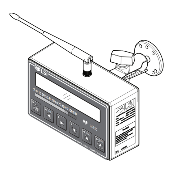
The GS550 system includes the cabin mounted GS550 radio display and compatible crane mounted sensors. The GS550 creates a two-way radio network with the sensors to bring required lift data to the operator. Hoist load, boom and jib angles, boom length, wind speed and pending two-block can be detected and indicated to the operator in real time. -
Page 7: Start-Up
Start-Up The GS550 must be correctly programmed for the system sensors installed. The GS550 powers up with several green lights flashing, this indicates that the display is waking up programmed sensors and creating a radio communication link with each. Once a reliable radio communication network is established, all green lights will remain lit without flashing. -
Page 8: Operation
Figure: GS550 front view Load Display The GS550 typically displays load information as follows: the number of parts of lines, the hoist indicator, the tare/no tare indicator, the weight, the weight units. Very large load values may overwrite the weight units and tare indication symbols. -
Page 9: Liquid Crystal Display (Lcd)
The green “M” (main) and “A” (auxiliary) load radio status green lights stay on when the GS550 has a reliable radio communication link to all programmed sensors. The radio status lights flash green when communication is intermittent or absent. The M refers to the first sensor programmed in the sensor list except anti-two-block. -
Page 10: Keypad
Keypad The keypad consists of six buttons used to control, consult, program, and troubleshoot the GS550 display and system. Each button has two functions; a primary (operation) function and a secondary (menu) function for navigation and programming. The secondary functions are described in the section GS550 Menu System. - Page 11 Step 2. Use Next to scroll from one limit to the next. Step 3. Use Up and Down to adjust a limit. When using the GS550 as a load indicator without programmed crane specific rated capacity charts the load limit is typically set to the lesser of the rope limit, the hoist limit, and the maximum allowed capacity as determined from the capacity charts.
-
Page 12: Menu System
Menu System There are five basic menus (level one) used to program, consult and control the GS550 system. Menu 1) Parts of Lines Menu 2) Crane Rigging Menu 3) Display Settings Menu 4) Installation Menu 5) System Diagnostic The basic menus include nested sub-menus (level two, three and four) designed to address specific tasks including adjusting values, choosing from lists and following “wizards”... -
Page 13: Menu Navigation
AZA. If the user password is forgotten, it can be changed as long as the administrator password is known. Forgotten password? Call LSI technical support (Houston, TX) at 888 819 4355 or contact your local LSI representative. GM550 v1043 FCC-IC.doc... -
Page 14: Menu Layout
The load sensor often shares the weight with multiple parts of line. For accurate load indication the GS550 must be programmed for the number of parts of line. Step 1. Press Menu → Enter to enter menu 1) Parts of Line. -
Page 15: Crane Rigging - Capacity Chart Selection
In order to indicate WLL the GS550 must be programmed with a valid rated capacity chart specific to the crane. The capacity chart programmed can be verified on the chart number page of the Information menu: press Info →... - Page 16 Step 5. After the last step has been completed the GS550 will display “Rigging ok” and then it will return to the operation display. If a sensor required by the selected capacity chart is not a part of the system or has not established communication with the GS550, then the GS550 will display “sensor invalid”.
-
Page 17: Display Settings
Metre Table: Weight units Language Future versions of the GS550 will include different display language options. Step 1. Press Menu → Next → Next → Enter → Next → Next to go to menu 3B) Display language. Step 2. Press Next to advance to the contrast adjustment page or press Exit twice to return to the operation display. -
Page 18: Contrast
Contrast Adjust the LCD contrast to optimize visibility. Step 1. Press Menu → Next → Next → Enter → Next → Next → Next to go to menu 3D) LCD contrast adjustment. Step 2. Use Up and Down to adjust the display contrast. Step 3. -
Page 19: System Diagnostic
Sensors listed here are not necessarily installed on the same crane as the GS550 and may be a part of a functioning GS550 system on a neighbouring crane. Programming a GS550 display for sensors from a different system will disable that system and render indication by both systems inaccurate. -
Page 20: Lockout Diagnostic
Step 4. Press Next to go to menu 5D4) Display internal temperature. Step 5. Press Next to go to menu 5D5) GS550 base station id. The base station id should be the same as the GS550 display serial number printed on the left side of the box Step 6. -
Page 21: Installation
Installation Display GS550 Important! Do not crack or puncture the membrane fascia. The GS550 display is splash and rain proof. Waterproofing depends in part on the integrity of the membrane. Important! Do not power wash the display. The GS550 display is not designed to withstand high-pressure washing devices that can erode the membrane fascia seal or create fissures in the membrane fascia. -
Page 22: Power Supply And Lockout Connection
5/16 inch bolt. The ground connection must be strong enough to sustain 3 Amp. Step 2. Connect the red wire to a fused accessory source, rated at least 3 Amps, that supplies +12 or +24 volts when the crane is on. The GS550 will automatically detect the voltage level and adjust itself. - Page 23 & green wires, see above. Step 7. Connect the yellow cable to the GS550. The connector is waterproof and well rated for external environments. Simply connect the cable to the display and gently tighten the nut. Do not put a kink in the yellow cable where it enters the connector;...
- Page 24 Yellow cable Red wire Black wire Battery Crane Power +12V or +24V Supply Figure: Connection without lockout Yellow cable To valve coil if normally closed is required Bosch relay White wire n.c. Red wire n.o. Black wire Battery +12V or +24V To valve coil if normally open is Crane Power Supply...
-
Page 25: Lockout Settings
Lockout Settings Warning, alarm and lockout control is programmed in this menu. The GS550 can be programmed to generate alarms and lockout for almost all programmed limits, and two-block. Furthermore, warnings are generated when approaching programmed load limits and rated capacity (when applicable). - Page 26 Lockout Triggers Different events can be programmed to cut voltage on the lockout wires of the yellow cable. Each lockout wire can be linked to a different combination of lockout conditions. Step 1. Press Menu → Next → Next → Next → Enter → Next → Next → Next→ Next →...
-
Page 27: Password Settings
• Maximum rope speed Lockout Relay Inversion WARNING! Inverting lockout relays will allow crane operation in the event the GS550 display fails. Operating a crane without a functioning anti-two-block system and load and angle indication is dangerous and may be against the law. -
Page 28: Datasheet
Datasheet Revision 2 GM550 v1043 FCC-IC.doc... -
Page 29: Load Cell
Important! The load cell antenna must not be in contact with metal. Important! The load cell antenna must have a clear line of sight to the GS550 display. Important! The load cell antenna must point to the left or to the right of the boom; it must not point directly to, or away from, the GS550 display. -
Page 30: Angle Sensors For The Boom Or Jib
Mounting Procedure The GS010 series angle sensors can be turned on by starting up the GS550 display to which they are programmed. The angle sensor can then assist in levelling itself with the red and green LED. -
Page 31: Angle Calibration Procedure № 1: Mechanical Set-Up
Tip: When the angle sensor is moved very slowly, it may take several seconds to see an update at the GS550 display. Instead move the sensor up a couple of degrees, and then bring it back down to where it should be. The small light on the angle sensor flashes when it transmits a new value to the display. -
Page 32: Angle Calibration Procedure № 2: Correct With The Gs550
Angle Calibration Procedure № 2: Correct with the GS550 Calibrate angle indication by adjusting the trim (offset) value in the GS550 display; the GS550 will then communicate the updated trim value to the sensor. Step 1. Position the boom at a precisely known angle. -
Page 33: Anti-Two-Block Switch Gs050
Press Bypass to silence the alarm until the next two- block event or simulation. If the switch has not been programmed to the display, this should be done before proceeding to step 2. See How to Add a Sensor to the GS550. Step 2. Position the sensor mounting bracket. - Page 34 Up to 8 in. (20 cm) diameter Boom base → Mount bracket below and behind sheave centre. Figure: Telescopic boom, anti-two-block switch placement for both live and dead end mounting If the head sheave diameter is between 8 and 16 inches (20-41 centimetres) then two mounting brackets will be required to permit both live and dead end mounting.
- Page 35 For live end mounting on multiple sheave blocks with sheaves greater than 16 inches (41 centimetres) in diameter consult your service representative. Mount bracket 2-4 in. (5-10 cm) Boom base → below sheave centre. Figure: Jib, rooster or other extension, anti-two-block switch placement for single part of line operation only For fast line weight installation place the anti-two-block switch mounting bracket directly below the sheave center as low and as close to the edge of the sheave as possible.
- Page 36 Step 3. Chain length adjustment № 1 – minimum boom angle i. At minimum boom angle, with no additional weight on the hook block and one part of line only, lift the boom just enough to have the hook block suspend and clear the sensor chain and weight.
- Page 37 Step 4. Chain length adjustment № 2 – maximum boom angle i. Raise the boom to the maximum angle. ii. Hoist slowly until the red two-block warning lights comes on and the buzzer sounds. Note the hoisting distance remaining; this distance must be great enough to allow the operator and the lockout system, if installed, to prevent a two-block event.
-
Page 38: Length Sensor Cable Reel
Length Sensor Cable Reel WARNING! Arc welding will damage LSI sensors, causing immediate failure or greatly reducing functional life. Arc welding on or near LSI equipment will void warranty. Keep LSI equipment well clear of any arc welding. The GS101 includes the LS101 cable reel and the GS011 angle/length sensor. The GS011 is concealed under the cover of the LS101, though the antenna is visible. -
Page 39: Mounting The Cable Reel
Step 6. Verify the boom length indicated on the GS550 LCD. Boom length is indicated following the length abbreviation “L”, typically on the first or second operation page. Boom length indicated should equal the actual total boom length. -
Page 40: Boom Length Calibration Procedure № 1: Mechanical Set-Up
Depending on the exact placement of the cable reel and the cable anchor the displayed length may differ from the actual length. Figure: GS550 LCD – typical operation page two with boom length indication Cable anchor Cable guide... -
Page 41: Boom Length Calibration Procedure № 2: Correct With The Gs550
Boom Length Calibration Procedure № 2: Correct with the GS550 If displayed boom length does not match actual boom length for retracted or extended boom and if it is not possible to easily correct by following Boom Length Calibration Procedure № 1 (previous page), then follow this procedure. -
Page 42: Radius Calculation
Telescopic boom cranes: install the length sensor (see Installation – Length Sensor Cable Reel). Make sure the length is displayed properly for retracted and extended boom. Lattice boom cranes, GS550 not programmed with rated capacity charts: the boom length must be entered manually in the display. This value must be adjusted Boom Length:150.0 + -... -
Page 43: Gm550 V1043 Fcc-Ic.doc Revision 2
If the radius displayed by the GS550 corresponds to the actual radius in all cases, the radius function is correctly calibrated. Be sure that all radius parameters have been carefully noted to facilitate re- calibration in the event of component or system upgrade, change, or re-installation. -
Page 44: Radius Parameters For A Lattice Crane
Radius Parameters for a Lattice Crane The radius calculation parameters highlighted in green must be measured on the crane and set into the radius settings of the GS550 display unit Jib mounting point Head sheave Jib offset angle Distance from head... -
Page 45: Radius Parameters For A Hydraulic Crane
Radius Parameters for a Hydraulic Crane The radius calculation parameters in green must be measured on the crane and set into the radius settings in the GS550 display. The sheave head length is the distance between the boom centerline and the center of the lower sheave. -
Page 46: Radius Display Troubleshooting
For accurate radius calculation the actual boom length and angle, and the jib length and angle must be correctly displayed by the GS550 and all radius parameters must be correctly measured and entered in the radius settings of the GS550 display. Before proceeding with troubleshooting confirm that all steps described at the beginning of the Radius Calculation section, including the radius parameters subsection, have been followed. -
Page 47: Advanced Radius Settings (Reference)
Advanced Radius Settings (Reference) On most cranes, the radius parameters described above should be sufficient to calibrate accurate radius indication. When the GS550 has been programmed with rated capacity charts additional radius parameters may facilitate fine tuning radius indication. With the most common Sheave Head:... -
Page 48: Wireless Wind Speed Sensor Gs020
The transmitter antenna must not contact any metal object. WARNING! Do not weld in proximity to LSI sensor/transmitters. Weld the mounting rod to the boom at the selected point. Screw the sensor/transmitter assembly to the mounting rod with the mounting screw. Note that washers should be screwed one to each side of the brass bushing of the sensor/transmitter assembly. -
Page 49: Wireless Load Pins
Wireless Load Pins WARNING! Do not pull on a load pin by the pigtail. LP011, LP015, and LP026 Step 1. Mount the load pin to the boom tip or block by replacing the pin of the wedge socket. The load pin is directional and must be oriented correctly to indicate load accurately. Install the pin so that the bracket embraces the wedge socket and prevents pin rotation. -
Page 50: Load Pin Transmitter Gs001
The transmitter antenna must not be in contact with any metal object. Step 2. Weld the mounting blocks where required. WARNING! Do not weld in proximity to LSI sensor/transmitters. Step 3. Mount the load pin transmitter on the mounting blocks. -
Page 51: Load Calibration: Load Pins, Line Riders And Compression Cells
Load Calibration: Load Pins, Line Riders and Compression Cells Important! Load indication by load pins, line riders and compression cells must be calibrated! This procedure applies to load pins, line riders and compression cells. This procedure must be followed at installation and every time thereafter the load sensor or load transmitter is changed. Flat bar load links (part numbers GC005, GC012, GC018, GC035, GC060, GC100, GC170 etc.) are factory calibrated, on site calibration is not required. - Page 52 Step 5. Press Exit three times to return to the operation display. Load indication by load pins, line riders and compression cells varies depending on the load sensor, the load transmitter and the installation. Recalibrate after every change in load sensor or load transmitter and when installing on a different machine.
-
Page 53: Four Point Lift
3. Slack Rope Each of these functions can be used to generate an alarm condition on the lockout wires of the GS550. Sum Load Indication When sum load indication is programmed the sum of the loads on the pre-determined load sensors is indicated by the operation display. -
Page 54: Imbalance
Imbalance Systems programmed for four load sensors and four load sum indication can be programmed with an imbalance sensor to warn against uneven load distribution or against unwanted rope payout if one corner of the load touches down before the others. The Imbalance Factor Limit The imbalance factor is the percent difference between the load on one load sensor and the average load on the other three. -
Page 55: Slack Rope
Slack Rope Systems programmed for four load sensors and four load sum indication can be programmed with a slack rope sensor to warn against unwanted rope payout when the load touches down. The Slack Rope Minimum Limit The slack rope sensor compares the sum load to an adjustable slack rope minimum limit. When the sum load goes below the slack rope limit a slack rope alarm is generated. -
Page 56: Data Logger
Data Logger The GS550 includes a data logger that records all significant events with a date and time stamp and actual sensor values. The data logger memory can hold over 16 000 records, this is equivalent to several days or several years of operation depending on the recording mode selected and machine use. -
Page 57: Date And Time
Step 1. Press Menu → Next → Next → Next → Enter → Next → Next → Next → Next → Next → Enter to go to menu 4F1) Data logger mode Step 2. Use Up and Down to select the data logger recording mode. Step 3. -
Page 58: The Sensor List
All sensors in the GS550 system are programmed in the sensor list. The GS550 uses information from all sensors in the sensor list. Conversely the GS550 will not use or display information from sensors that are not programmed to the sensor list. If a sensor is removed from the crane then it must be removed from the sensor list. -
Page 59: How To Remove A Sensor From The Gs550
How to Remove a Sensor from the GS550 Step 1. Determine the sensor to be removed. If more than one sensor of the same type has been added to the sensor list then determine the radio identification number (id) of the sensor to be removed before proceeding. -
Page 60: Portable Download Tool
Portable Download Tool The portable download tool consists of a compatible Palm personal digital assistant (PDA) and LSI software kit. Using the portable download tool it is possible to update firmware, install rated capacity charts or export data logger files without removing the display from the crane. Wireless... -
Page 61: Installing Palm Software
Transfer Firmware Files from a Personal Computer to the Palm Two types of files can be sent to the Palm: • LSI files identified by the filename extension .pdb, including firmware, rated capacity charts and system configuration updates for the GS550. -
Page 62: Transfer Firmware Files From The Palm To A Gs550
Select All from the drop down menu in the upper right hand corner. c. Select LSI Firmware. Step 2. On the GS550 display, press and hold Bypass while starting the display. The display will enter a safer mode and allow firmware updates. -
Page 63: Transfer Data Logger Files From The Gs550 To The Palm
Select All from the drop down menu in the upper right hand corner c. Select LSI Datalogger. Step 2. Align the infrared ports of the Palm and the GS550 about 6 inches (10 centimetres) apart. Step 3. On the Palm, receive the file: a. -
Page 64: Data Logger Viewer
The Data logger viewer is a software application used to display on a personal computer (PC) a log file generated by the GS550 data logger. To transfer data logger files from a GS550 to a PC see the section “Transferring Files”. -
Page 65: Full Report
C:\Program Files\Palm\PALM_NAME\Backup\ Note: PALM_NAME is the actual name given to the Palm. Step 4. Select the log file to open. Only .pdb files generated by the LSI software in the Portable Download Tool are supported. LSI_08_13_2004_15_31_48.PDB Example: A typical file name for a log file generated by a GS550 datalogger Full Report To export the full report to Excel, click on the Full Report button in the tool bar. -
Page 66: Wind Report
Wind Report To create a wind report in Excel, click on the Wind Report button in the tool bar. Figure: Excerpt of a Wind Report Column Description Date Date of event recorded Time Time of event recorded Sensor ID Wind speed sensor id number Wind (mph) Average wind speed in the period Nb. -
Page 67: Maintenance
Maintenance Replacing Sensor Batteries All Sensors Except the GS050 Anti-Two-Block Switch What Is Needed • A hex key 5/32 in. (approximately 3.97 mm) • A flat bladed screwdriver • One (1) new high quality “D” cell battery: 3.6 V lithium, or alkaline •... -
Page 68: The Gs050 Anti-Two-Block Switch
The GS050 Anti-Two-Block Switch What Is Needed • An adjustable wrench • Four (4) new high quality “C” cell batteries: 3.6 V lithium, or alkaline • RTV non-corrosive silicone Tip: Four 3.6 volt lithium “C” cell batteries will provide over four years of battery life, while four alkaline “C”... -
Page 69: Replacing Antennas
Replacing Antennas Sensors The GS series sensor antenna (part number TA011) is identified with a blue strip. The TA011 is replaceable. Slightly damaged antennae (bent, sheathing scratched, plastic head cap TA011 antenna missing etc.) should not be replaced unless otherwise identified as preventing with identifying proper sensor function. - Page 70 Coat the exposed metal foot of the new antenna with an electrical insulating compound by carefully inserting it in the mouth of the compound tube. Hold the new antenna by the black plastic sheathing and guide it through the hole in the White nylon hex bolt sensor box.
-
Page 71: Load Cell Maintenance
If the transmitter box has been hit and the box does not fit perfectly to the underlying link, please call LSI to have it repaired. Engraving on the transmitter box sides will not affect reading. - Page 72 If one or both hex nuts are scratched, it will not affect the load cell readings on operation. If the bolt head is bent or sheared verify the transmitter box fits tightly to the load cell link before contacting LSI for replacement bolts.
-
Page 73: Trouble Shooting
Example of having two usernames on side of the screen to the same PC. One is “LSI” and the see the time of day on other one is “lsi”. This could be really the upper left. 2) Press... -
Page 74: Instructions To The User
To reduce potential radio interference to other users, the antenna type and its gain should be so chosen that the equivalent isotropically radiated power (e.i.r.p.) is not more than that permitted for successful communication. Antenna List LSI P/N: TA001 Description: ¼ wave monopole... - Page 75 To reduce potential radio interference to other users, the antenna type and its gain should be so chosen that the equivalent isotropically radiated power (e.i.r.p.) is not more than that permitted for successful communication. Antenna List LSI P/N: TA011 Description: ¼ wave monopole...
-
Page 76: Menu Outline
Menu Outline 4D2) Crane capacity chart interpolation 1) Parts of Line 4D3) Out of charts default working load limit 4D4) Enable start section 4D5) Enable stop section 2) Crane Rigging 4D6) Retracted boom length tolerance 4D7) Intermediate boom length tolerance 4D8) Extended boom length tolerance 3) Display Settings 4D9) Radius tolerance... - Page 77 5D2) Time clock battery test 4I2) Set-up sensor repeater 5D3) External power supply voltage 5D4) Display internal temperature 5) System Diagnostic 5D5) GS550 base station identification number 5A) System Sensors Diagnostic 5E) Digital Input Diagnostic 5B) Radio Network Diagnostic 5E4) Blue wire status...
- Page 78 Alarm Bypassed protection 4H19 Alarm level Green wire status and self-test Automatic value calibration wizard Green wire lockout trigger GS550 base station identification number Backlight mode Blue wire (digital input status) Height offset Blue wire lockout trigger Boom angle tolerance...
- Page 79 number Orange wire lockout trigger Set administrator password Out of charts default working load limit Set user password Set-up sensor repeater Parts of Line Sheave head length parallel 4C18 Parts of Line menu password protection Sheave head length perpendicular 4C17 Password Settings Sheave radius 4C19...
- Page 80 LSI Contact Information USA Corporate Office: 9223 Solon, Suite A Houston, TX 77064 Toll Free Phone: (888) 819 4355 Direct Phone: (281) 664 1330 Toll Free Fax: (888) 238 4099 Direct Fax: (281) 664 1390 Email: sales@loadsystems.com Dubai Corporate Office: Y02 Saif Zone P.O.
Need help?
Do you have a question about the GS550 and is the answer not in the manual?
Questions and answers