Table of Contents
Advertisement
Quick Links
- 1 Start-Up
- 2 Antenna Position
- 3 Power Supply and Lockout Connection
- 4 Gs050 Anti-Two Block Switch and Gs075 All-In-One Anti-Two-Block Switch and Weight
- 5 Set the ID Number
- 6 Replacing the Anti-Two-Block Battery
- 7 Replacing Gs075 All-In-One Anti-Two-Block Switch and Weight Battery
- Download this manual
& Anti-Two-Block
INSTALLER AND USER'S MANUAL
INSTALLER AND USER'S MANUAL
!
WARNING! The GS375 system is designed as an operator aid and is in no way a
!
!
WARNING! Carefully read and understand this manual before proceeding.
!
GM375
.20090303
REV
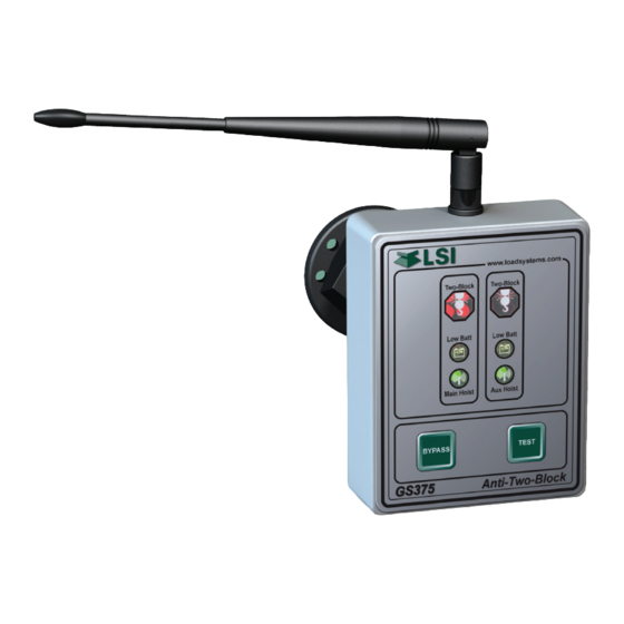
GS375 Display
w w
w w
T w o
T w o
- B l
- B l
o c k
o c k
L o w
B a t
t
M a
i n H
o i s
t
B Y
P A
S S
G S
G S
G S
3 7 5
3 7 5
3 7 5
A n
A n
substitute for safe operating practice.
w w
w . l
. l o
o a
o a
d s
d s
y s t
y
y s t
e m
T w o
T
T w o
s . c
- B l
- B l
B l o
o m
o c k
c k
k
L o w
B a t
t
A u
x H
o i s
t
T E
S T
t i - T
t i - T
w o
w o
- B l
- B l
o c k
o c k
Manufacturers of Wireless
Weighing Systems
www.loadsystems.com
Advertisement
Table of Contents

Related Manuals for LSI GS375


Summary of Contents for LSI GS375
- Page 1 - B l o c k o c k WARNING! The GS375 system is designed as an operator aid and is in no way a substitute for safe operating practice. WARNING! Carefully read and understand this manual before proceeding. GM375 .20090303...
- Page 2 Failure to install all parts, or replacing parts or components with parts or components not supplied by , may lead to system failure, serious injury or death. The GS375 System The GS375 System...
-
Page 3: Table Of Contents
1.3 RECOMMENDED OPERATING PROCEDURES ........14 CONDITIONS ........4 6.3 EXCLUSION OF OTHER 2. INSTALLATION WARRANTIES ........14 2.1 DISPLAY GS375 ........5 6.4 EXCLUSION ........15 2.1a Mounting Bracket ........5 6.5 LIMITATION OF LIABILITY ....15 2.1b Antenna Position ........6 6.6 RECOMMENDED PRACTICES ..15 2.1c Power Supply and Lockout Connection ..6 2.2 GS050 ANTI-TWO BLOCK SWITCH... -
Page 4: Introduction
When an anti-two-block switch goes from safe to alarm condition, the GS375 will activate its alarm and lockout wires within 0.05 seconds. The lockout wire can be connected to a relay to block crane functions such as boom out or hoist up. -
Page 5: Installation
ø2.5 in. min. 0.906 part on the integrity of the membrane. flat surface IMPORTANT! Do not power wash the display. The GS375 display is not designed to 0.594 withstand high-pressure washing devices that 0.594 can erode the membrane fascia seal or create fissures in the membrane fascia. -
Page 6: Antenna Position
2. Connect the red wire to a fused accessory source, rated at least 3 amperes, that supplies +12 or +24 volts when the machine is in use. The GS375 will automatically detect the voltage level and adjust itself. 3. Lockout wire (if required): connect the green wire to a Bosch relay coil terminal. -
Page 7: Gs050 Anti-Two Block Switch And Gs075 All-In-One Anti-Two-Block Switch And Weight
Figure: Anti-two-block switch placement on a telescopic boom • The anti-two-block switch antenna should have a clear line of sight to the GS375 If the head sheave diameter is between 8 and 16 display; in most cases this means mounting... -
Page 8: Gs075 Installation
A) Anti-two-block 4. Adjust chain length as required, see sub-section prevented with switch triggers safety margin two-block alarm Chain length adjustment. 5. Test system function. Figure: Chain length adjustment - Minimum boom angle The GS375 System The GS375 System... - Page 9 the hoisting distance remaining; this distance must be great enough to allow the operator and the lockout system, if Increase Increase installed, to prevent a two-block event. If necessary, add chain between the sensor and weight to increase warning distance. If still insufficient, contact your service representative.
-
Page 10: Operation
In this case Procedure № 1 may be is in alarm. preferable. In normal operation, the GS375 display should 1. Press the Bypass & Test buttons simultaneously indicate one or two steady green lights, depending until the display makes a double beep, after if one or two anti-two-block switches are installed. -
Page 11: Maintenance
MAINTENANCE MAINTENANCE Replacing the Anti-Two- nylon hex bolt of the wire rope. Tighten well. Replacing the Anti-Two- 7. Pull and release the wire rope, the light emitting Block Battery Block Battery diode (LED) on the bottom of the sensor should IMPORTANT! Replace all the batteries of flash red. -
Page 12: Replacing The Sensor Antenna
Do not overtighten. hole in which it is seated. Place the old antenna aside. 11. Reinstall the sensor if necessary. 12. Verify that the sensor functions properly. GS050 GS075 Figure: Pull out the antenna The GS375 System The GS375 System... -
Page 13: Certification Notes
Antenna List installation. If this equipment does cause harmful LSI P/N: ..TA008 interference to radio or television reception, which can be determined by turning the equipment off and Description: .1/2 wave dipole on, the user is encouraged to try to correct the MFG: . -
Page 14: Lsi Product Limited Warranty - 2009/02/16
(60) days, whichever is longer. LSI document) (the “Warranty Period”), when on a LSI reserves the right to require from you the user or installed and used in accordance with specifications owner of the Products, prior to determining if the Limited LSI Installer and User’s Manual, as... -
Page 15: Exclusion
EXPRESSLY DISCLAIMED. NO ORAL OR WRITTEN of the possibility of such damages. In any event, the LSI OR ITS LSI arising from any cause of action or INFORMATION OR ADVICE GIVEN BY total liability of EMPLOYEES... - Page 16 LSI Contact Information Technical Support: Technical Support: LSI Technical Support is available 24 hours a day, 7 days a week from our Houston and Dubai locations. Please direct all technical support questions to either of these locations or contact us via email: techsupport@loadsystems.com...
Need help?
Do you have a question about the GS375 and is the answer not in the manual?
Questions and answers