
Summary of Contents for Cambridge Sound Management Qt Emitters
- Page 1 Conference Room Edition ® A speech protection system designed for conference rooms Installation and Operations Guide...
- Page 2 Emitter layout – normal installation – two rows of emitters Emitter layout – when to use up to 4 rows of emitters Controller and privacy sign layout Installation Pre-wiring Installing qt emitters Custom cabling guidelines Installing the controller and privacy signs System set-up and calibration Acoustic calibration...
-
Page 3: Safety
SA FE TY Safety Important Safety Instructions: Read these instructions. Keep these instructions. Heed all warnings. Follow all instructions. Do not use this apparatus near water. Indoor use only. Clean only with dry cloth. Do not block any ventilation openings. Install in accordance with the manufacturer’s instructions. Do not install near any heat sources such as radiators, heat registers, stoves, or other apparatus (including amplifiers) that produce heat. -
Page 4: Packing List
4-gang adaptor plate for control module (used for 3-gang EU/UK boxes) ▪ Automatically lighted privacy signs ▪ 1-gang adaptor plate for privacy signs ▪ Power supply ▪ Qt Emitters ▪ 16 ft audio cables ▪ 50 ft homerun audio cable ▪ 50 ft two-conductor cables for privacy signs ▪... -
Page 5: Introduction
Introduction General The Qt Conference Room Edition (QtCRE) from Cambridge Sound Management is a very cost- effective solution to provide confidential speech privacy for conference rooms, executive offices and suites, boardrooms and other sensitive spaces, to the immediate areas surrounding such spaces. For convenience we may refer to all such rooms as conference rooms although that may not be their actual use. -
Page 6: Full Feature List
INT R OD UCT IO N Alternatively, levels may be set using the standard settings chart later in the manual, which will work fine for most installations. The QtCRE control module supports one zone of sound masking with 2 cable homeruns. Each run supports up to 60 emitters. -
Page 7: Planning The System
PLA N NI N G T H E S Y S T EM Planning the System Sound Masking Guidelines This manual covers system installation of the controller, privacy signs and emitters, as well as masking level setting and system maintenance. This introduction section discusses guidelines to ensure effective sound masking coverage. -
Page 8: Emitter Spacing And Ceiling Height
PLA N NI N G T H E S Y S T EM Emitter spacing and ceiling height Spacing between emitters generally should follow the same rules as for other CSM direct field masking systems, i.e. should be not less than the ceiling height above the finished floor. The English dimensions are based on America drop ceiling tile sizes (24x24”, 24x48”). -
Page 9: Emitter Layout – Normal Installation – Two Rows Of Emitters
PLA N NI N G T H E S Y S T EM Emitter layout – Normal installation – two rows of emitters Place the first row adjacent any party wall between the conference room and exterior spaces at ½ the height of the ceiling or less, e.g. -
Page 10: Emitter Layout – When To Use Up To 4 Rows Of Emitters
PLA N NI N G T H E S Y S T EM Emitter layout – When to use up to 4 rows of emitters Consider using 4 rather than 2 rows of emitters in the conditions described below. Four rows may not be required if no speech is intelligible beyond the first two rows. -
Page 11: Controller And Privacy Sign Layout
PLA N NI N G T H E S Y S T EM Controller and privacy sign layout Options on how to control the system It is important to understand how the system will be used and controlled to decide the location of the controller and privacy signs. -
Page 12: Installation
INSTAL LATI O N Installation Pre-wiring Homerun Four Channel Distribution The 50’ CAT distribution line supplied with the base kit should be sufficient as the homerun for almost all installations. It may be replaced by a longer CAT cable to the first emitter without excessive loss or impact privacy signal level difference between the first and last emitters on the line. - Page 13 INSTAL LATI O N Power supply In most cases the 24v power supply will need to be located remotely, with a cable run from the power supply to the controller. In some cases a wall plate such as the Vanco 120614X permits in-wall running of the power wire to an AC plug on the exterior of the wall.
- Page 14 INSTAL LATI O N Connection to privacy signs Run a separate cable from the controller mounting location to each lighting location. Do not daisy chain signs as this may cause the lights to be of different brightness. Two 50 ft. (15.2m) plenum rated cables are provided with the kit.
-
Page 15: Installing Qt Emitters
INSTAL LATI O N Installing Qt Emitters Important Considerations: Each run has a maximum of 60 emitters! ▪ Each run supports a maximum cable length of 1000 ft. ▪ Each home run cable attached to the control module should be labeled by Zone # and Run #. - Page 16 INSTAL LATI O N Run the cable to next designated tile specified on emitter layout and wiring diagram. Tie cables up to structure or suspend from deck as required by local building code. On the next emitter, connect this cable to the INPUT jack. Repeat Steps 4 through 9 for the remaining emitters on the home run.
-
Page 17: Custom Cabling Guidelines
INSTAL LATI O N Custom Cabling Guidelines Important Considerations: Use solid conductor 24 AWG CAT cable that meets local code requirements. If the system is installed in a return air plenum, the cable must be plenum rated. Shielding is not required. Unshielded twisted pair (UTP) cable is acceptable. Snagless boots are not required. - Page 18 INSTAL LATI O N Flush mount with supplied box Cut hole in wall to dimensions x by x (use template) and run cables to this hole. After the cables have been run to the hole in the wall, place the flush mount box in the wall (make sure up is actually up) and snap the four clips that clamp to the back side of the drywall surface.
- Page 19 INSTAL LATI O N Surface mount on a suitable 4-gang electrical box (3-gang using EU/UK hardware) 4-gang electrical box (pre-installed or retrofitted) – after the cables have been run to the box, use four supplied screws to attach the wall plate adapter. (In the case of EU 3-gang boxes, use M3 or M3.5 screws as needed –...
- Page 20 INSTAL LATI O N Surface mount directly to the wall Surface or panel mount of back plate – either with cables through hole (if cables can be run through the wall) or out the side to end up on the surface of the wall or mounting point. Mark holes with template, open up larger holes for cables if desired, run cables, attach back plate.
- Page 21 INSTAL LATI O N Mounting options for the privacy signs There are several options for mounting the privacy signs. These options allow for mounting on a variety of wall surfaces, including glass. 1-gang box (North American NEMA or UK/EU types) If using a 1-gang box, retrofit or pre-installed, first run cable to the box.
- Page 22 INSTAL LATI O N Surface mount (double-sided tape), with cabling running through wall or on surface of wall. If running a cable through the wall, get this into position first. Note that the exit point for the cable on the back of the sign is centered across the bottom Connect the cable using the push terminals.
- Page 23 INSTAL LATI O N Mounting on glass plus using “hider” plate for other side of glass surface Best practices – it’s best to use self-adhesive tape, NOT a 1-gang box (because of sound transmission issues). If mounting the signs to either side of the same wall, don’t locate the boxes closer than 2 ft. from each other.
-
Page 24: System Set-Up And Calibration
SYST E M SE T- UP AND CALIBR ATIO N System Set-Up And Calibration Acoustic calibration Direct Field technology minimizes the need for equalization or measurements during system setup. Sensitivity and efficiency of the emitter array is known and listeners are typically in the direct field of emitters without an intervening acoustical ceiling which would change the effective output level and frequency response of the system. -
Page 25: System Configuration Via The Front Pane
SYST E M SE T- UP AND CALIBR ATIO N System Configuration via the Front Panel After the Qt CRE is mounted and the emitters have been tested, it is time to configure the Qt CRE for general operation. The front panel display shows system information and allows for adjustment of the masking and the auxiliary audio input levels. -
Page 26: User Mode
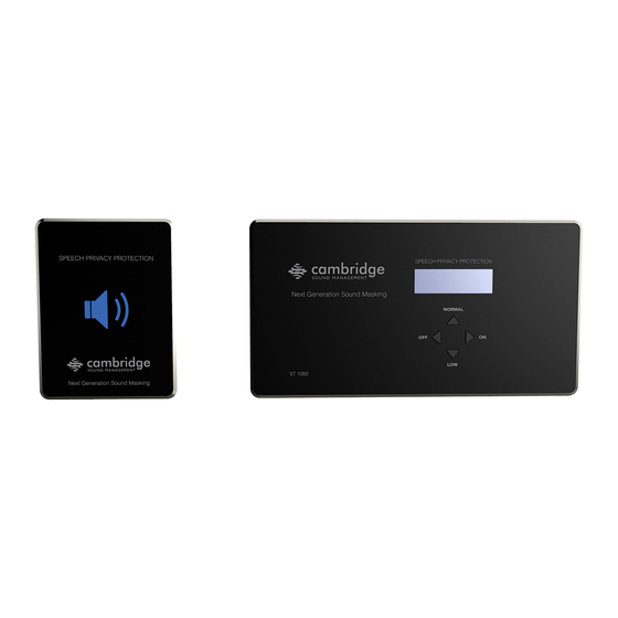
SYST E M SE T- UP AND CALIBR ATIO N User Mode User Mode gives minimal functionality and simple intuitive display read-outs. Buttons NORMAL Correct level for speech privacy in the conference room ▪ Optional lower level masking ▪ Note: does not give full privacy Turns system on to last used level (normal or low) ▪... -
Page 27: Set-Up Mode
SYST E M SE T- UP AND CALIBR ATIO N Set-Up Mode Changing from User Mode to Set-Up Mode: Hold down the ON and OFF buttons (left and right) for 5 seconds, then the display will blink three times (500ms on / 500ms off, etc.) In set-up mode information and settings can be accessed by pushing the right (ON) and left (OFF) buttons. - Page 28 SYST E M SE T- UP AND CALIBR ATIO N Exiting Set-Up mode to return to User Mode: Hold down the ON and OFF buttons (left and right) for 5 seconds, then the display will blink three times. Commissioning ramp With traditional sound masking systems, a commission process is use that ramps up the sound masking over several weeks’...
-
Page 29: System Acoustic Calibration
SYST E M SE T- UP AND CALIBR ATIO N System acoustic calibration Setting the masking volumes can be approached in one of three ways: Best: The Qt system has a companion iPad app that takes acoustic measurements and relays the results to the control module via Bluetooth to set the appropriate masking sound level. - Page 30 SYST E M SE T- UP AND CALIBR ATIO N e.g. lightweight “accordion” doors or those with poor or no seals at the top and bottom or low quality lightweight or sound “leaky” demountable walls, it may not be feasible to obtain adequate privacy between them whether or not sound masking is installed around their perimeter.
-
Page 31: Troubleshooting
SYST E M SE T- UP AND CALIBR ATIO N Troubleshooting Privacy signs do not illuminate Check wiring polarity Note that the small switch on the side of the controller must be set to the “up” position (closer to the top of the case) for the lights to work. The “down” setting enables the external USB jack, used for firmware updates or for the optional Bluetooth dongle supplied the Qt100 iPad app. - Page 32 SYST E M SE T- UP AND CALIBR ATIO N Error Codes If one or more errors exist in the sound masking system, an eight digit error code is displayed on the LCD display (scroll forward to the “Error” screen). The error state is indicated by an eight digit code of the form: Error: 0_000000 Error Code for Zone 1...
-
Page 33: Warranty
® Cambridge Sound Management, Inc. (the “warrantor”) will, for a period of five (5) years, starting with the date of purchase, warrant that the Emitters (the “speakers”) will be free of defects in materials and workmanship that interfere with proper operation as a sound masking, ®... -
Page 34: Zone Destination Records
ZON E DE S TI NAT IO N R EC OR D S Zone Destination Record Zone 1 Run 1 Run 2 Settings Record Volumes: Zone: Masking: Input A: Installation / Service: Company name: Install date: Phone: Qt Conference Room Edition Installation and Operations Guide page 34... -
Page 35: Hole Cut Guide For Flush Mount Box
HO L E CU T G UID E F O R F LU S H M OU N T BOX Qt Conference Room Edition Installation and Operations Guide page 35... - Page 36 Qt Conference Room Edition Installation and Operations Guide page 36...
-
Page 37: Hole Cut Guide For Privacy Sign
HO L E CU T G UID E F O R PR IVA CY S IG N 90mm 113mm Wire exit area Hole cut guide for privacy sign Cut hole wire in (6mm) from lower edge of sign Hole shape is not important, but be careful to stay within area to be covered by sign. - Page 38 Cambridge Sound Management, Inc. 404 Wyman St. Suite 200 Waltham, MA 02451 USA cambridgesound.com © Copyright 2015 Cambridge Sound Management Inc. Quiet Technology, Qt, Cambridge Sound Management, and the logo are trademarks of Cambridge Sound Management.
- Page 39 This two page document is an addendum to the Qt Conference ® Room Edition manual. Please read. NOTE: Below are supplemental images for the content contained on page 14 of the Qt Conference Room Edition manual. ® Connection to privacy signs Run a separate cable from the controller mounting location to each lighting location.
- Page 40 This two page document is an addendum to the Qt Conference ® Room Edition manual. Please read. NOTE: Two new options have been added to the program menu of the Conference Room Edition. These options are outlined below: ® 1. Contact Closure = Normal/Off or Normal/Low. When this option is set to “Normal/Off”, the contact switch will toggle between Normal Volume (Contact Open) and Off (Contact Closed).
Need help?
Do you have a question about the Qt Emitters and is the answer not in the manual?
Questions and answers