Table of Contents
Advertisement
Advertisement
Table of Contents
Troubleshooting

Related Manuals for Zapi ACE3


Summary of Contents for Zapi ACE3
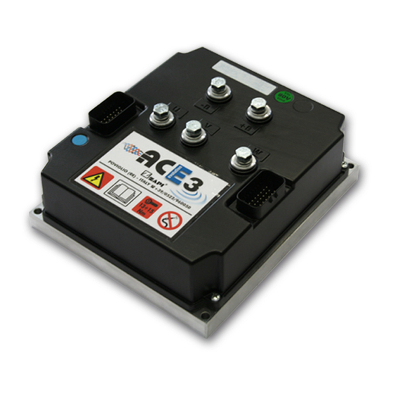
- Page 1 ELECTRONIC • OLEODYNAMIC • INDUSTRIAL EQUIPMENTS CONSTRUCTION Via Parma, 59 – 42028 – POVIGLIO (RE) – ITALY Tel +39 0522 960050 (r.a.) – Fax +39 0522 960259 e-mail: zapi@zapispa.it – web: www.zapispa.it User Manual ACE3 INVERTER Publication N°: AFFZP0BB Edition: 08 May 2017...
- Page 2 Under no circumstances will Zapi S.p.A. be held responsible to third parties for damage caused by the improper use of the present publication and of the device/devices described in it. Zapi spa reserves the right to make changes or improvements to its products at any time and without notice.
- Page 3 2.5 Diagnoses ........................ 12 3 DRAWINGS ......................... 13 3.1 Mechanical drawing – ACE3 / ACE3 Power ............. 13 3.2 Connection drawing – ACE3 Traction Standard ............14 3.3 Connection drawing – ACE3 Traction Premium ............15 3.4 Connection drawing – ACE3 Pump Standard ............16 ...
- Page 4 INVERTER SETTINGS ....................... 40 7.1 Settings overview ..................... 40 7.2 Settings description ....................41 7.2.1 PARAMETER CHANGE ................41 7.2.2 SET OPTIONS ................... 45 7.2.3 ADJUSTMENT ................... 53 7.2.4 SPECIAL ADJUST..................58 Page – 4/139 AFFZP0BB – ACE3 – User Manual...
- Page 5 Troubleshooting of master-uC warnings ........... 110 9.4 Warnings overview (supervisor uC) ................ 120 9.4.1 Troubleshooting of supervisor-uC warnings ..........120 10 SPARE PARTS ......................... 122 11 PERIODIC MAINTENANCE ....................123 12 APPENDICES ........................124 AFFZP0BB – ACE3 – User Manual Page – 5/139...
- Page 6 12.1.4 Lift & Lower acquisition ................128 12.1.5 Steering acquisition .................. 128 12.1.6 TESTER functionality ................129 12.1.7 Alarm Logbook ..................129 12.2 Appendix B: Zapi Smart Console user guide............130 12.2.1 Operational Modes ................... 130 12.2.2 The keyboard .................... 131 12.2.3 Home Screen .................... 131 ...
-
Page 7: Introduction
1.1.2 Manual revision This revision replaces all previous revisions of this document. Zapi has put much effort to ensure that this document is complete and accurate at the time of printing. In accordance with Zapi policy of continuous product improvement, all data in this document are subject to change or correction without prior notice. -
Page 8: About The Controller
It is responsibility of the vehicle manufacturer to identify the correct standards and to ensure that the vehicle meets these standards. As a major electrical control component, the role of a Zapi motor controller should be carefully considered and relevant safety precautions taken. It has several features which can be configured to help the system integrator meeting vehicle safety standards. -
Page 9: Specifications
2 SPECIFICATIONS 2.1 General features Within the ZAPIMOS family, the ACE3 inverter (E stands for evolution) is a controller designed to control AC induction, BLDC and PMAC motors, in the range from 10 kW to 20 kW continuous power, used in a variety of battery-powered material-handling trucks. -
Page 10: Technical Specifications Of Ace3
Digital control based upon microcontroller Voltage: ................... 24, 36, 48, 80 V Maximum current ACE3 PW 24V: ..........700 A (RMS) for 2' Maximum current ACE3 PW 36-48V: ........650 A (RMS) for 2' Maximum current ACE3 PW 80V: ..........550 A (RMS) for 2' 1 hour current rating ACE3 PW 24V: .......... -
Page 11: Functional Features
High efficiency of motor and battery due to high frequency commutations. Double microcontroller for safety functions. Self-diagnosis, the faults can be monitored through the Console or through Zapi MDI/Display. Modification of parameters through the programming console. -
Page 12: Diagnoses
Diagnoses can be provided in two ways: the digital console can be used, which gives detailed information about failures; as an alternative the failure code is sent on the CAN bus and can be monitored by means of Zapi PC CAN Console. Page – 12/139... -
Page 13: Drawings
3 DRAWINGS 3.1 Mechanical drawing – ACE3 / ACE3 Power Other versions (without power fuse, with base-plate and with other heat sinks) exist. AFFZP0BB – ACE3 – User Manual Page – 13/139... -
Page 14: Connection Drawing – Ace3 Traction Standard
3.2 Connection drawing – ACE3 Traction Standard Page – 14/139 AFFZP0BB – ACE3 – User Manual... -
Page 15: Connection Drawing – Ace3 Traction Premium
3.3 Connection drawing – ACE3 Traction Premium AFFZP0BB – ACE3 – User Manual Page – 15/139... -
Page 16: Connection Drawing – Ace3 Pump Standard
3.4 Connection drawing – ACE3 Pump Standard Page – 16/139 AFFZP0BB – ACE3 – User Manual... -
Page 17: Connection Drawing – Ace3 Pump Premium
3.5 Connection drawing – ACE3 Pump Premium AFFZP0BB – ACE3 – User Manual Page – 17/139... -
Page 18: Description Of The Connectors
Standard and Premium versions of ACE3 and for Traction and Pump configurations. For each I/O pin, the default Zapi function is indicated. The function of each pin can be changed in the customized software. Also, some I/O pins can have special functionality depending on the HW configuration of the controller. -
Page 19: Ace3 Traction Standard
-Batt. Freewheeling diode to A17 is built-in. CAN_L1 CAN bus 1 low-level signal. CAN_H1 CAN bus 1 high-level signal. NCAN CAN bus negative supply. Motor-temperature-sensor input. It is possible to use a digital or analog (PTC) sensor. AFFZP0BB – ACE3 – User Manual Page – 19/139... -
Page 20: Ace3 Pump Standard
CAN_L1 CAN bus 1 low-level signal. CAN_H1 CAN bus 1 high-level signal. NCAN CAN bus negative supply. PTHERM Motor-temperature-sensor input. It is possible to use a digital or analog (PTC) sensor. Page – 20/139 AFFZP0BB – ACE3 – User Manual... -
Page 21: Ace3 Traction Premium
-Batt. Freewheeling diode to A17 is built-in. CAN_L1 CAN bus 1 low-level signal. CAN_H1 CAN bus 1 high-level signal. NCAN CAN bus negative supply. Motor-temperature-sensor input. It is possible to use a digital or analog (PTC) sensor. AFFZP0BB – ACE3 – User Manual Page – 21/139... - Page 22 1 A maximum continuous current (driving to -Batt). Freewheeling diode to B1 is built-in. CAN_L2 CAN bus 2 low-level signal. CAN_H2 CAN bus 2 high-level signal. Third Hall-sensor input, active low. FREE Free pin. Page – 22/139 AFFZP0BB – ACE3 – User Manual...
-
Page 23: Ace3 Pump Premium
CAN_L1 CAN bus 1 low-level signal. CAN_H1 CAN bus 1 high-level signal. NCAN CAN bus negative supply. PTHERM Motor-temperature-sensor input. It is possible to use a digital or analog (PTC) sensor. AFFZP0BB – ACE3 – User Manual Page – 23/139... - Page 24 1 A maximum continuous current (driving to -Batt). Freewheeling diode to B1 is built-in. CAN_L2 CAN bus 2 low-level signal. CAN_H2 CAN bus 2 high-level signal. Third Hall-sensor input, active low. FREE Free pin. Page – 24/139 AFFZP0BB – ACE3 – User Manual...
-
Page 25: Input Devices
5 INPUT DEVICES This chapter describes the external devices needed to complete the ACE3 installation kit. 5.1 Key Input 5.1.1 Function Start key switch of the vehicle, generally connected to the KEY input. It supplies with the battery voltage the controller logic circuitry and it also pre-charges the DC-link capacitors at key-on. -
Page 26: Accelerator Unit
On the other hand, before calibration it results mapped over the default 0 – 5 V range. Before PROGRAM VACC After PROGRAM VACC Page – 26/139 AFFZP0BB – ACE3 – User Manual... -
Page 27: Other Analog Control Unit
PC CAN Console or of the Smart Console, as: A3MT2B ZP1.13 Where: A3MT = ACE3 traction controller (M stands for “Master μC”, S for “Slave μC”) (A3MP = ACE3 pump controller) 2 = poles pair number B = 64 pulses/rev... -
Page 28: Sin/Cos Sensor And Hall Sensors
5.5.1 Sin/Cos sensor and Hall sensors ACE3 Premium provides a special interface to connect an absolute sin/cos sensor or three Hall sensors for special applications that use brushless motor. For more details about sensors installation also refer to paragraphs 6.2.6 and 6.2.7. -
Page 29: Installation Hints
For special applications or requirements these values can be reduced. For safety reasons, we recommend the use of protected fuses in order to prevent the spreading of particles in case the fuse blows. AFFZP0BB – ACE3 – User Manual Page – 29/139... -
Page 30: Hardware Installation
They must be tightened onto the controller power posts with a torque in the 13 Nm – 15 Nm range. The ACE3 module should only be connected to a traction battery. Do not use converters outputs or power supplies. For special applications please contact the nearest Zapi Service Centre. -
Page 31: Wirings: Can Bus Connections And Possible Interferences
Power cables Module Module Module The red lines are CAN wires. The black boxes are different modules, for example a traction controller, a pump controller and a display connected via CAN bus. AFFZP0BB – ACE3 – User Manual Page – 31/139... - Page 32 Of course also the diameter of the cables concurs in the voltage drops described before (a greater diameter brings to a lower impedance), so in this last example the cable between negative battery terminal and the center of the ground Page – 32/139 AFFZP0BB – ACE3 – User Manual...
-
Page 33: Wirings: I/O Connections
For information about the pin assignment see chapter 4. 6.2.5 Connection of the encoder ACE3 controller can handle different types of encoder. To control AC motor, it is necessary to install an incremental encoder with two phases shifted by 90°. The encoder supply can be 5 V or 12 V. -
Page 34: Connection Of A Sin/Cos Sensor
It is necessary to specify in the commercial order the type of sensor used, in terms of power supply, electronic output and n° of pulses for revolution, because the logic unit and the software must be set in the correct way by Zapi lines. -
Page 35: Connection Of Hall Sensors
(trapezoidal wave shape). A PMSM is a BLDC when, by turning its shaft lightened, the electromotive force between two motor terminals is of the shape trapezoidal. To control BLDC motor with Zapi inverter, it is necessary to three Hall sensors. Hall sensors power supply can be +5 or +12 V. -
Page 36: Insulation Of Truck Frame
6.3 Protection and safety features 6.3.1 Protection features The ACE3 inverter is protected against: Battery polarity inversion It is necessary to install a main contactor in order to protect the inverter against reverse battery polarity and for safety reasons. -
Page 37: Safety Features
The safety of the machine is strongly related to installation. Length, layout and screening of electrical connections have to be carefully designed. ZAPI is always available to cooperate with customers in order to evaluate installation and connection solutions. Furthermore, ZAPI is available to develop new SW or HW solutions to improve the safety of the machine according to customer requirements. - Page 38 ISOLATION: use anti-static containers when transferring ESD-sensitive material. Page – 38/139 AFFZP0BB – ACE3 – User Manual...
-
Page 39: Various Suggestions
SCR choppers. If it is necessary to use two or more control units (traction and lift for ex.), they must belong to the ZAPIMOS family. During battery charge, disconnect asynchronous from the battery. AFFZP0BB – ACE3 – User Manual Page – 39/139... -
Page 40: Inverter Settings
PWM EV2 EVP CLOSE DELAY PWM EV3 HYDRO TIME PWM EV4 PWM EV5 MAX MOTOR TEMP. STOP MOTOR TEMP. A.SENS.MAX SE A.SENS.MIN SE A.SENS.MAX CE A.SENS.MIN CE MOT.T. T.CUTBACK VACC SETTING Page – 40/139 AFFZP0BB – ACE3 – User Manual... -
Page 41: Settings Description
CO = CANopen controllers N = none The parameters and the functionalities described in the following paragraphs are referred to ZAPI Standard software. They could be different in any other customized software releases depending on customer requests. 7.2.1 PARAMETER CHANGE... - Page 42 0% ÷ 100% This parameter defines the speed of the pump motor when 5 5TH PUMP SPEED speed is requested. It represents a percentage of the maximum (by 1% steps) pump speed. Page – 42/139 AFFZP0BB – ACE3 – User Manual...
- Page 43 Hard-and-Soft function is active. It represents a percentage of (T, TM) (by 1% steps) TOP MAX SPEED. Note: by default H&S function is not present on ACE3. 0% ÷ 100% This parameter defines the maximum traction speed when an CTB. STEER ALARM...
- Page 44 (by steps of 0.05 s) 0 s ÷ 20 s This parameter defines how long the hydraulic steering remains HYDRO TIME active after the traction request is released. (by steps of 0.1 s) Page – 44/139 AFFZP0BB – ACE3 – User Manual...
-
Page 45: Set Options
DC motor power bridge is active or one of the valve outputs is active Note: options 2, 4, 5 and 6 are not effective on ACE3 This parameter decides the configuration for the hour meter HM CUSTOM 2 OPT. - Page 46 This setting is useful especially for traction application. When the truck is travelling over a ramp and the driver wants to stop it by gravity, the motor must not be powered anymore, until the truck stops. Page – 46/139 AFFZP0BB – ACE3 – User Manual...
- Page 47 H&S switch and the accelerator, without the tiller input. ON = H&S function is enabled OFF = H&S function is disabled Note: by default this function is not present on ACE3. AFFZP0BB – ACE3 – User Manual Page – 47/139...
- Page 48 A23. The temperature sensor is a KTY 83-130 PTC (positive thermal coefficient resistance) OPTION#3 = an analog motor thermal sensor is connected to A23. The temperature sensor is a PT1000 PTC (positive thermal coefficient resistance). Page – 48/139 AFFZP0BB – ACE3 – User Manual...
- Page 49 STEERING TYPE connected to the controller. (T, TM) NONE = steering module is not present on the truck; ACE3 does not wait for any CAN message from the EPS and it does not apply EPS and braking steering cutback. OPTION#1 = EPS is present and it is configured with encoder + toggle switches, whose signals are acquired and related data transmitted to ACE3 via CAN bus.
- Page 50 ABSENT = output not enabled, no load on B18. only) DIGITAL = B18 manages a voltage-controlled PWM- modulated valve. The PWM frequency is 1kHz and the duty cycle depends on PWM EV3 (ADJUSTMENT list). Page – 50/139 AFFZP0BB – ACE3 – User Manual...
- Page 51 If the steering performance of the truck does not match your requirements even after you have entered the right truck dimensions, contact a Zapi technician in order to determine if a custom steering table has to be created.
- Page 52 This parameter activates the acquisition of motor speed sensor ABS.SENS.ACQUIRE used for PMSM (Permanent-Magnets Synchronous Motor). (A – Only custom HW with sin/cos) Contact Zapi Technicians for a detailed description of the acquisition procedure. Behavior on a slope. Behavior on a slope STOP-ON-...
-
Page 53: Adjustment
36V, 48V, 72V, 80V Volt Fine adjustment of the key voltage measured by the controller. ADJUST KEY VOLT. Calibrated by Zapi production department during the end of line test. Volt Fine adjustment of the battery voltage measured by the ADJUST BATTERY controller. - Page 54 See paragraph 8.3 0V ÷ 25.5V This parameter records the maximum steering-control voltage STEER ZERO VOLT when it is in the straight-ahead position (T,TM) (by steps of 0.1V) See paragraph 8.3 Page – 54/139 AFFZP0BB – ACE3 – User Manual...
- Page 55 MDI hour meter (connected via the Serial Link). OFF, ON In order to cancel the CHECK UP NEEDED warning, set this CHECK UP DONE parameter ON after the required maintenance service. (T, TM, P, CO) AFFZP0BB – ACE3 – User Manual Page – 55/139...
- Page 56 This parameter specifies the duty-cycle (t ) of the PWM EB VOLTAGE applied to the main-contactor output (A18) during the first (by 1% steps) second after the activation signal that causes the electromechanical brake to release. Page – 56/139 AFFZP0BB – ACE3 – User Manual...
- Page 57 Reference limits of the linear reduction are MAX MOTOR TEMP and TEMP. MOT. STOP. Volt See the PROGRAM VACC procedure in paragraphs 0 and VACC SETTING 12.2.6. AFFZP0BB – ACE3 – User Manual Page – 57/139...
-
Page 58: Special Adjust
Note: SPECIAL ADJUST. must only be accessed by skilled people. To change settings in this group of settings, a special procedure is needed. Ask for this procedure directly to a Zapi technician. In SPECIAL ADJUST. there are factory-adjusted parameters that should be changed by expert technicians only. - Page 59 (Factory adjusted). This parameter defines the power-bridge PWM PWM AT LOW FREQ frequency at low speed. NOTE: only Zapi technicians can change this value through a special procedure. (Factory adjusted). This parameter defines the power-bridge PWM PWM AT HIGH FREQ frequency at high speed.
- Page 60 OFF ÷ ON This parameter enables or disables the console to change settings. RS232 CONSOLLE Reserved. NOTE: only Zapi technicians can change this value. 0 ÷ 56 This parameter defines the offset of the CANopen frame IDs. ID CANOPEN OFST...
-
Page 61: Hardware Setting
7.2.5 HARDWARE SETTING The HARDWARE SETTING parameters group includes the motor-control-related parameters. Only those parameters the user can modify are here described. For descriptions and teaching about missing parameters contact a Zapi technician. HARDWARE SETTING Parameter Allowable range Description 0 Hz ÷ 600 Hz This parameter defines the maximum motor speed. -
Page 62: Hydro Setting
RUNNING = ACE3 drives the pump motor only upon an associated request (for example a lift request). OPTION #1 = ACE3 does not drive the pump motor, but the truck integrates hydraulics and ACE3 acts as master controller managing a valve. The output that drives the hydraulic valve (for example EVP) is activated at key-on. -
Page 63: Tester Function
The actual motor voltage delivered is the product of MOTOR VOLTAGE and INDEX OVEMOD. . Hertz (0.1 Hz) Frequency of the current sine-wave that the inverter is FREQUENCY supplying to the motor. AFFZP0BB – ACE3 – User Manual Page – 63/139... - Page 64 Newton Meter (0.1 Nm) Estimation of the motor torque. MOTION TORQUE NM Degrees (1°) Current steering-wheel angle. When the steering is STEER ANGLE straight ahead STEER ANGLE is zero. (T, TM) Page – 64/139 AFFZP0BB – ACE3 – User Manual...
- Page 65 (T, TM) OFF/ON Status of the forward-inching input (B6). B6 FW-INCH (TS) OFF/ON Status of the backward-inching input (B13). B13 L-BW-IN (TS) OFF/ON Status of the TILLER/SEAT input (A6). A6 SEAT AFFZP0BB – ACE3 – User Manual Page – 65/139...
- Page 66 In case of warning it shows the related warning code. WARNING SYSTEM (CO) Percentage (1%) This value shows the setpoint of proportional TARGET EVP1 electrovalve EVP1 in CAN Open configuration. (CO) Page – 66/139 AFFZP0BB – ACE3 – User Manual...
- Page 67 It shows the status of the EV3 output (B18). B18 OUTPUT EV3 (A – Only Premium version) OFF/ON It shows the status of the EV4 output (B19). B19 OUTPUT EV4 (A – Only Premium version) AFFZP0BB – ACE3 – User Manual Page – 67/139...
- Page 68 (1km) Odometer: overall distance traveled by the truck. ODOMETER KM (T, TM, CO) Reserved for Zapi technicians use. CPU TIME F US Reserved for Zapi technicians use. CPU TIME M US Page – 68/139 AFFZP0BB – ACE3 – User Manual...
-
Page 69: Supervisor Microcontroller
Voltage of analog input A3. A3 POT#1 Volt (0.01V) Voltage of analog input A10. A10 POT#2 Volt (0.01V) Voltage of analog input B2. B2 POT#3 Volt (0.01V) Voltage of analog input B10. B10 POT#4 AFFZP0BB – ACE3 – User Manual Page – 69/139... -
Page 70: Set-Up Procedure For Traction Inverter
(CO) 7.4 Set-up procedure for traction inverter This section describes the basic set-up procedure for the ACE3 inverter in traction configuration. If you need to replicate the same set of settings on different controllers, use the SAVE and RESTORE sequence (see chapter 8); otherwise go down the following sequence. -
Page 71: Sin/Cos-Sensored Case
Inverter goes down the procedure automatically, every phase is marked by a different message on display. In case of problems, mainly in the first phase, please: Check that PM motor pole pairs is set correctly. AFFZP0BB – ACE3 – User Manual Page – 71/139... -
Page 72: Set-Up Procedure For Pump Inverter
7.5 Set-up procedure for pump inverter This section describes the basic set-up procedure for the ACE3 inverter in pump configuration. If you need to replicate the same set of settings on different controllers, use the SAVE and RESTORE sequence (see chapter 8); otherwise go down the following sequence. -
Page 73: Other Functions
0 – 5 V range. Before ‘PROGRAM VACC’ After ‘PROGRAM VACC’ PROGREAM VACC can be carried out through Zapi PC CAN Console or through Zapi Smart Console. For the step-by-step procedures of the two cases, refer to paragraphs 0 and 12.2.6. -
Page 74: Program Lift / Lower Function
The values to be acquired are organized in the ADJUSTEMNT group; they are: STEER RIGHT VOLT STEER LEFT VOLT STEER ZERO VOLT See paragraphs 12.1.5 or 12.2.8 for acquiring procedure. Page – 74/139 AFFZP0BB – ACE3 – User Manual... -
Page 75: Acceleration Time
ACCEL DELAY, in this case 2.5 s. Case 3 (green trace in the graph): Final-speed setpoint = 150 Hz ACCEL DELAY = 2,5 s Acceleration time results: ∙ 2.5 3,75 Figure 1: Acceleration time AFFZP0BB – ACE3 – User Manual Page – 75/139... -
Page 76: Deceleration Time
The deceleration time results: ∙ 2.5 3,75 Note: This example is valid for all the braking-related parameters: DECEL. BRAKING, INVER. BRAKING, RELEASE BRAKING, TILLER BRAKING, PEDAL BRAKING, SPEED LIMIT BRK, STEER BRAKING. Page – 76/139 AFFZP0BB – ACE3 – User Manual... -
Page 77: Acceleration Smoothness
0 rpm. Values have not a phisycal meaning: 1 means linear ramp, higher values (up to 5) result in smoother the accelerations. Figure 2: Smoothness Note: This example is valid for ACC SMOOTH, BRK SMOOTH, INV SMOOTH. AFFZP0BB – ACE3 – User Manual Page – 77/139... -
Page 78: Steering Curve
CURVE CUTBACK = 30% STEER DEAD ANGLE = 40° STEER ANGLE 1 = 50° STEER ANGLE 2 = 80° This parameters set builds the speed profile represented in the graph below. Page – 78/139 AFFZP0BB – ACE3 – User Manual... -
Page 79: Throttle Response
8.8 Throttle response The ACE3 controls the truck speed by means of a not linear function of the accelerator position, as to provide a better resolution of the speed control when the truck is moving slowly. For the definition of such response, the following parameters are used: ... -
Page 80: Nlc & Neb Output
MC VOLTAGE = 70% MC VOLTAGE RED = 70% The contactor is closed by applying 70% of duty-cycle to the coil and then it is reduced to 49% (70% of 70%). Page – 80/139 AFFZP0BB – ACE3 – User Manual... -
Page 81: Battery-Charge Detection
4) Charge percentage is dynamically updated basing on the energy from step 3. Threshold values for the battery charge can be modified by means of BAT.MAX.ADJ. and BAT.MIN.ADJ. as to adapt the battery-charge detection to the specific battery in use. AFFZP0BB – ACE3 – User Manual Page – 81/139... -
Page 82: Evp Control
EVP current from zero up to the maximum. CLOSE DELAY determines the current decrease rate, i.e. it defines the time needed to decrease the EVP current from the maximum down to zero Page – 82/139 AFFZP0BB – ACE3 – User Manual... - Page 83 MAX EVP in a time equal to OPEN DELAY. In the same way, when the lowering request is released, the current set-point is linearly reduced down to zero in a time equal to CLOSE DELAY. AFFZP0BB – ACE3 – User Manual Page – 83/139...
-
Page 84: Torque Profile
1. Not overtaking the maximum torque profile of the motor. 2. Superimposing a limiting profile to the maximum torque as to get different drive performances (Eco mode, Medium performance, High performance). Torque profile Torque curves Page – 84/139 AFFZP0BB – ACE3 – User Manual... -
Page 85: Steering Table
STEERING AXLE MM: axle width of the axle where the steering wheels are. All three previous parameters must be expressed in millimeters. OPTION#1 = three-wheels predefined steering table. OPTION#2 = four-wheels predefined steering table Geometrical steering-related parameters. AFFZP0BB – ACE3 – User Manual Page – 85/139... -
Page 86: Faults Diagnostic System
9 FAULTS DIAGNOSTIC SYSTEM The fault diagnostic system of ACE3 controller consists of two main groups of faults: ALARMS Faults which cause the power section to stop, meaning the power bridge opens and, when possible, the main contactor opens and the electromechanical brake is applied. - Page 87 Start-up, stand-by, EB is applied, POSITIVE LC OPEN Key re-cycle 0xFFD5 running Traction/Pump, valves stopped MC is opened, EB is Valves or FIELD ORIENT KO applied, Traction/Pump, Running 0xFFFD Traction/Pump valves stopped AFFZP0BB – ACE3 – User Manual Page – 87/139...
- Page 88 MC is opened , EB is applied, SPEED FB. ERROR Running Key re-cycle 0xFFAF EVP stopped MC is opened, EB is Valves or ENCODER ERROR Running 0xFF52 applied, Traction/Pump, Traction/Pump Page – 88/139 AFFZP0BB – ACE3 – User Manual...
- Page 89 EB is applied, Key re-cycle WRONG SET KEY 0x3101 running Traction/Pump, valves stopped MC is not closed, WRONG SET Start-up, stand-by, EB is applied, Key re-cycle 0x3100 BATTERY running Traction/Pump, valves stopped AFFZP0BB – ACE3 – User Manual Page – 89/139...
-
Page 90: Troubleshooting Of Master-Uc Alarms
3) LOGIC FAILURE #2 Cause Fault in the hardware section of the logic board which deals with voltage feedbacks of motor phases. Troubleshooting The failure lies in the controller hardware. Replace the controller. Page – 90/139 AFFZP0BB – ACE3 – User Manual... - Page 91 “dirty”. This alarm inhibits the machine operations. Troubleshooting Try to switch the key off and then on again, if the alarm is still present replace the logic board. AFFZP0BB – ACE3 – User Manual Page – 91/139...
- Page 92 Cause The error between the Id (d-axis current) setpoint and the estimated Id is out of range. Troubleshooting Ask for assistance to a Zapi technician in order to do the correct adjustment of the motor parameters. 12) IQ MISMATCHED Cause The error between the Iq (q-axis current) setpoint and the estimated Iq is out of range.
- Page 93 Ask for assistance to Zapi in order to verify that the software diagnoses are in accordance with the type of coil employed. If the problem is not solved, it could be necessary to replace the controller.
- Page 94 Check the motor leakage to truck frame. If the motor connections are OK and there are no external low impedance paths, the problem is inside the controller. Replace it. Page – 94/139 AFFZP0BB – ACE3 – User Manual...
- Page 95 If the alarm occurs while the motor is running, check: motor connections; that the LC power contact closes properly, with a good contact; if no problem is found, the problem is inside the controller. Replace it. AFFZP0BB – ACE3 – User Manual Page – 95/139...
- Page 96 22) POWER MISMATCH Cause The error between the power setpoint and the estimated power is out of range. Troubleshooting Ask for assistance to a Zapi technician about the correct adjustment of the motor parameters. 23) SEAT MISMATCH Cause This alarm can appear only in a Traction + Pump configuration.
- Page 97 Part Number. According with this “sign”, only the customized firmware can be uploaded. Troubleshooting Upload the correct firmware. Ask for assistance to a Zapi technician in order to verify that the firmware is correct. 26) ENCODER ERROR Cause...
- Page 98 Troubleshooting LC contacts are not working. Replace the LC. If LC contacts are working correctly, contact a Zapi technician. 31) CONTACTOR DRIVER Cause The LC coil driver is not able to drive the load. The device itself or its driver circuit is damaged.
- Page 99 Check the connections between the controller outputs and the loads. Collect information about characteristics of the coils connected to the two drivers and ask for assistance to a Zapi technician in order to verify that the maximum current that can be supplied by the hardware is not exceeded.
- Page 100 Replace the controller. In case the problem is not solved, replace the motor. 42) SHORT CIRCUIT KO Cause The HW dedicated to detect faults on power bridge does not work properly Page – 100/139 AFFZP0BB – ACE3 – User Manual...
- Page 101 In case the problem is not solved, replace the logic board. 47) WRONG SET KEY Cause The measured key voltage is not the right one for the inverter. AFFZP0BB – ACE3 – User Manual Page – 101/139...
- Page 102 Record the value stored inside the HARDWARE BATTERY RANGE parameter in the SPECIAL ADJUST. list and contact a Zapi technician. In case the problem is not solved, replace the logic board.
-
Page 103: Alarms – Supervisor Uc
MC is not closed, EB is applied, Key re-cycle WRONG ENC SET Start-up 0XFF51 Traction/Pump, valves stopped MC is opened, Stand-by, ANALOG INPUT Key re-cycle 0XFFFA EB is applied, running traction/pump stopped AFFZP0BB – ACE3 – User Manual Page – 103/139... -
Page 104: Troubleshooting Of Supervisor-Uc Alarms
Troubleshooting: Compare the values read by master and slave through the TESTER function. Ask for the assistance to a Zapi technician. If the problem is not solved, replace the logic board. 2) W.SET. TG-EB Cause: Supervisor microcontroller has detected that the master microcontroller has... - Page 105 This is a safety related test. The master μC has detected a supervisor μC wrong set point. Troubleshooting: Check the matching of the parameters between master and supervisor. Ask for assistance to a Zapi technician. If the problem is not solved, replace the logic board. 9) OUT MISMATCH XX Cause: This is a safety related test.
- Page 106 Part Number. According with this “sign”, only the customized firmware can be uploaded. Troubleshooting Upload the correct firmware. Ask for assistance to a Zapi technician in order to verify that the firmware is correct. 11) ANALOG INPUT Cause: This alarm occurs when the A/D conversion of the analog inputs returns frozen values, on all the converted signals, for more than 400 ms.
-
Page 107: Warnings – Master Uc
COIL SHOR. EVAUX EV stopped EV on Valve EV request 0xFFF1 MC is opened (the Start-up, Valves command is released), CONT DRIV EV XX stand-by, 0xFFE8 EB is applied, Request running Traction/Pump, valves AFFZP0BB – ACE3 – User Manual Page – 107/139... - Page 108 THERMIC SENS. KO stand-by, 0x4211 speed is reduced running Traction controller reduces the max Start-up, TH. PROTECTION current linearly from stand-by, 0x4210 Imax (85°C) down to running 0A (105°C) Page – 108/139 AFFZP0BB – ACE3 – User Manual...
- Page 109 EB is applied, STEER SENSOR KO Continuous Key re-cycle 0xFFB3 traction/pump stopped Save again the MC stays closed, EB is M/S PAR CHK MISM Start-up parameter and Key applied, 0xFFC6 re-cycle Traction/Pump, valves AFFZP0BB – ACE3 – User Manual Page – 109/139...
-
Page 110: Troubleshooting Of Master-Uc Warnings
If the problem is not solved, replace the logic board. 4) DATA ACQUISITION Cause: Controller in calibration state. Troubleshooting: The alarm ends when the acquisition is done. Page – 110/139 AFFZP0BB – ACE3 – User Manual... - Page 111 Check the wirings. If the motor direction is correct, swap the sin and cos signals. If the motor direction is not correct, swap two of the motor cables. If the problem is not solved, contact a Zapi technician. 9) ENCODER D.ERR Cause: This alarm occurs only when the controller is configured as PMSM and the feedback sensor selected is the encoder.
- Page 112 16) VACC OUT OF RANGE Cause: The CPOT input read by the microcontroller is not within the MIN VACC ÷ MAX VACC range, programmed through the PROGRAMM VACC function (see paragraph 8.1). Page – 112/139 AFFZP0BB – ACE3 – User Manual...
- Page 113 If the problem is not solved, replace the logic board. 17) PEDAL WIRE KO This is not implemented in ACE3. Troubleshooting: Ask for help to a Zapi technician. 18) FORW + BACK...
- Page 114 The maximum current gain parameters are at the default values, which means the maximum current adjustment procedure has not been carried out yet. Troubleshooting: Ask for assistance to a Zapi technician in order to do the adjustment procedure of the current gain parameters. 25) COIL SHOR. EVAUX Cause: This alarm occurs when there is an overload of one or more EV driver.
- Page 115 27) WRONG SLAVE VER. Cause: Wrong software version on supervisor uC. Troubleshooting: Upload the correct software version or ask for assistance to a Zapi technician. 28) SENS MOT TEMP KO Cause: The output of the motor thermal sensor is out of range.
- Page 116 The controller has restored the default settings. If a CLEAR EEPROM has been made before the last key re-cycle, this warning informs you that EEPROM was correctly cleared. Troubleshooting: A travel demand or a pump request cancel the alarm. Page – 116/139 AFFZP0BB – ACE3 – User Manual...
- Page 117 37) PEV NOT OK Cause: The PEV connector (B1, only for ACE3 Premium version) is not connected to the battery or the voltage is different from expected. This alarm occurs if one output among EVP, EV1, EV2, EV3, EV4 and EV5 is present or the AUX OUT function is active (POSITIVE EB = 1 or 2).
- Page 118 43) WARNING SLAVE Cause: Warning on supervisor uC. Troubleshooting: Connect the Console to the supervisor uC and check which alarm is present. Page – 118/139 AFFZP0BB – ACE3 – User Manual...
- Page 119 Check the sensor ohmic value and the sensor wiring. If the sensor is OK, improve the cooling of the motor. If the warning is present when the motor is cool, replace the controller. AFFZP0BB – ACE3 – User Manual Page – 119/139...
-
Page 120: Warnings Overview (Supervisor Uc)
2) PARAM RESTORE Cause: The controller has restored the default settings. If a CLEAR EEPROM has been made before the last key re-cycle, this warning informs you that EEPROM was correctly cleared. Page – 120/139 AFFZP0BB – ACE3 – User Manual... - Page 121 If the alarm occurs permanently, it is necessary to replace the controller. If the alarm disappears, the previously stored parameters will be replaced by the default parameters. AFFZP0BB – ACE3 – User Manual Page – 121/139...
-
Page 122: Spare Parts
10 SPARE PARTS Recommended spare parts for ACE3 inverters are here listed. Part number Description ACE3 Version C16590 Protected 500 A strip UL Fuse. 36/48V, 650 A 36/48V, 600 A C16589 Protected 400 A strip UL Fuse. 80V, 550 A C16588 Protected 350 A strip UL Fuse. -
Page 123: Periodic Maintenance
During periodic checks, if a technician finds any situation that could cause damage or compromise safety, the matter should be bought to the attention of a Zapi agent immediately. The agent will then take the decision regarding operational safety of the machine. -
Page 124: Appendices
Zapi PC CAN Console and Zapi Smart Console. The description focuses on the basic information about connection and settings. For additional functionalities available for both tools, it is suggested to contact Zapi technicians in order to receive more detailed information or dedicated documentation. - Page 125 Once you have chosen the node you want to connect to, start the connection. Insert the password in order to have the possibility to change the parameters: choose “Configuration” “Enter Password”. Type the password: “ZAPI” AFFZP0BB – ACE3 – User Manual...
-
Page 126: Parameter Download
Once you have selected the menu inside that resides the parameter you want to change, it is possible to modify the value using the “+” and “–“ buttons. Click on the “Store” button to save the changes on EEPROM. Page – 126/139 AFFZP0BB – ACE3 – User Manual... -
Page 127: Program Vacc
Select the Enable switch, if any; Select the direction switch (either forward or backward); Depress the pedal to its maximum excursion. Displayed values will vary accordingly to operator inputs. AFFZP0BB – ACE3 – User Manual Page – 127/139... -
Page 128: Lift & Lower Acquisition
Choose “Adjustment” menu. Select the value to acquire by pressing “acquiring” button, the acquisition will start: the procedure is the same described for Lift & Lower acquisition in the previous paragraph. Page – 128/139 AFFZP0BB – ACE3 – User Manual... -
Page 129: Tester Functionality
Update user can update alarm logbook; Clear user can clear alarm logbook on inverter EEPROM; Close closes the window; Print prints alarm logbook data on the selected printer. AFFZP0BB – ACE3 – User Manual Page – 129/139... -
Page 130: Appendix B: Zapi Smart Console User Guide
Zapi can provide the serial cable compatible with Molex SPOX connector used in Console Ultra. CAN bus connection The Smart Console can connect to an existing CAN line and connect with any Zapi controller inside this line. Main features of this operational mode: ... -
Page 131: The Keyboard
Green LED can blink in certain cases which will be described better in the following sections. 12.2.3 Home Screen After showing the Zapi logo, the HOME SCREEN will appear on the display: AFFZP0BB – ACE3 – User Manual Page – 131/139... -
Page 132: Connected
First line displays the controller firmware. Second line shows controller voltage, controller current and hour meter. Last line shows the current alarm code, if present. Press OK to access the MAIN MENU. Page – 132/139 AFFZP0BB – ACE3 – User Manual... -
Page 133: How To Modify Parameters
Keep LEFT/RIGHT button pressed to continuously repeat the value modification (“auto-repeat” function): this function will speed up the procedure in case many parameter values must be changed. AFFZP0BB – ACE3 – User Manual Page – 133/139... -
Page 134: Program Vacc
to select the direction switch (either forward or backward); to depress the pedal to its maximum excursion. Displayed values vary accordingly to operator inputs. Page – 134/139 AFFZP0BB – ACE3 – User Manual... -
Page 135: Lift And Lower Acquisition
It is possible to acquire all the values in only one session. At the end you can press ESC and the console will prompt a request to confirm/discard changes. AFFZP0BB – ACE3 – User Manual Page – 135/139... -
Page 136: Steer Acquisition
Compared to standard console Ultra, the TESTER menu has been deeply modified. Now it shows four variables at once: use UP/DOWN keys to scroll the list. 12.2.10 Alarms ALARMS menu has changed from Console Ultra. Display shows all controller alarms at once. Page – 136/139 AFFZP0BB – ACE3 – User Manual... -
Page 137: Download Parameter List Into A Usb Stick
Name of the menu where parameter is placed tools (“Name menu” column). File name is generated as an hexadecimal code of the time and date of save. This codification prevents any overwrite of previously saved files. AFFZP0BB – ACE3 – User Manual Page – 137/139... - Page 138 If the directory does not exist, it is created when download is carried out for the first time. Page – 138/139 AFFZP0BB – ACE3 – User Manual...
- Page 139 During download the led blinks slowly to indicate the console is running. When download has finished USB stick can be unplugged safely. Do not remove USB stick during download or the file will result empty or corrupted. AFFZP0BB – ACE3 – User Manual Page – 139/139...
Need help?
Do you have a question about the ACE3 and is the answer not in the manual?
Questions and answers