Table of Contents

Related Manuals for Zapi VCM 2uC


Summary of Contents for Zapi VCM 2uC
- Page 1 ELECTRONIC • OLEODYNAMIC • INDUSTRIAL EQUIPMENTS CONSTRUCTION Via Parma, 59 – 42028 – POVIGLIO (RE) – ITALY Tel +39 0522 960050 (r.a.) – Fax +39 0522 960259 e-mail: zapi@zapispa.it – web: www.zapispa.it User Manual VCM ZAPI...
- Page 2 Under no circumstances will Zapi S.p.A. be held responsible to third parties for damage caused by the improper use of the present publication and of the device/devices described in it. Zapi spa reserves the right to make changes or improvements to its products at any time and without notice.
-
Page 3: Table Of Contents
Description of the console RESTORE function ............38 9.5 Description of the throttle regulation ................. 38 9.6 Description of the battery charge detection setting ........... 39 9.7 Description of ALARMS menu .................. 40 AFDZP0BA – VCM Zapi 2uC - User Manual Page - 3/54... - Page 4 PERIODIC MAINTENANCE TO BE REPEATED AT TIMES INDICATED ......54 APPROVAL SIGNS COMPANY FUNCTION INITIALS SIGN PROJECT MANAGER TECHNICAL ELECTRONIC MANAGER VISA SALES MANAGER VISA Publication N°: AFDZP0BA Edition: November 2013 Page - 4/54 AFDZP0BA – VCM Zapi 2uC - User Manual...
-
Page 5: Introduction
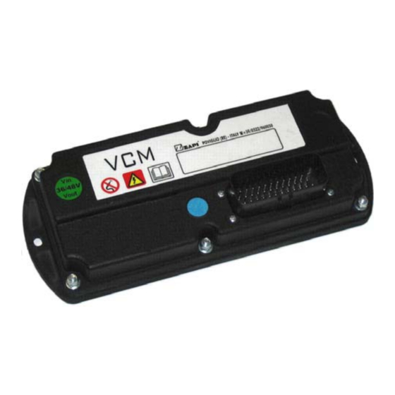
The high number of I/Os accommodates a large number and wide range of vehicle controls and sensors. It can easily work in conjunction with Zapi motor controllers and other CAN devices. The VCM offers many digital and analog inputs for interfacing with microswitches or potentiometers. - Page 6 The VCM can be supplied in two different configurations: Standard Version 36/48V, 80V, with a 35 poles Ampseal connector Premium Version 36/48V, 80V, with an additional second 23 poles Ampseal connectors, enhanced I/O STANDARD VERSION PREMIUM VERSION Page - 6/54 AFDZP0BA – VCM Zapi 2uC - User Manual...
-
Page 7: Specification
+5V output supply [n°] .................... 2 CAN Interface[n°] ....................2 IP Protection ..................... IP65 External Operating temperature range ..........-40°C;+50°C VCM can be operated with 36V or 48V battery without any hardware modification. AFDZP0BA – VCM Zapi 2uC - User Manual Page - 7/54... -
Page 8: Block Diagram
3 BLOCK DIAGRAM Page - 8/54 AFDZP0BA – VCM Zapi 2uC - User Manual... -
Page 9: Specification For The I/O Interaces
When full load connected, the voltage between the key switch contacts must be lower than 0.1V. If the microswitch to be used has different characteristic, it is suggested to discuss them and their application with Zapi technicians. 4.2 Analog inputs The analog units can consist of potentiometers or Hall effect devices. -
Page 10: Outputs
(typically 4-20mA). It is suggested to discuss about analog inputs and their application with Zapi technicians to properly configure each input signal range according to the analog device connected . -
Page 11: Incremental Encoder
6. Different built-in programmable levels for dither amount & frequency 7. Overload protection, short circuit protection and open load protection Please refers to chapter 7 or contact Zapi for further information about outputs. All the output pins can be converted to input pins if necessary. Please contact Zapi for further information 4.4 Incremental encoder... -
Page 12: Can Bus
It is possible configure them via hardware in order to obtain one of these two possible configurations: 1) Two independent lines, each one managed by only one uC. Master and Supervisor uC are able to communicate each other by local Can Bus. Page - 12/54 AFDZP0BA – VCM Zapi 2uC - User Manual... - Page 13 Can Bus. VERY IMPORTANT It is necessary to specify in the order the type of configuration used because the logic unit must be set in the correct way by Zapi. AFDZP0BA – VCM Zapi 2uC - User Manual Page - 13/54...
-
Page 14: Additional Features
5 ADDITIONAL FEATURES 5.1 Real Time Clock Real-time clock function is available. It is possible to modify the calendar using the Zapi Console and adjusting properly the related parameters in the menu “ADJUSTMENT” (See Chapter 9). Built in 3V battery is present. -
Page 15: Installation Hints
Do not connect the controller to a battery with a nominal voltage different than the value indicated on the controller label. A higher battery voltage may cause valves driver section failure. A lower voltage may prevent the logic operating. AFDZP0BA – VCM Zapi 2uC - User Manual Page - 15/54... -
Page 16: Wirings: Can Connections And Possible Interferences
In the following figures there is an overview of wrong and right layouts of the cables routing. Wrong Layout: Can Bus Power cables Module Module Module Page - 16/54 AFDZP0BA – VCM Zapi 2uC - User Manual... - Page 17 In this case the power cables starting from the two similar controllers must be as short as possible. Of course also the diameter of the cable concurs in the voltage AFDZP0BA – VCM Zapi 2uC - User Manual Page - 17/54...
-
Page 18: Wirings: I/O Connections
IP65. 6.3.2 Safety Features ZAPI controllers are designed according to the prEN954-1 specifications for safety related parts of control system and to UNI EN1175-1 norm. The safety of the machine is strongly related to installation; length, layout and Page - 18/54 AFDZP0BA –... -
Page 19: Double Microcontroller Architecture
ZAPI is always available to cooperate with the customer in order to evaluate installation and connection solutions. Furthermore, ZAPI is available to develop new SW or HW solutions to improve the safety of the machine, according to customer requirements. - Page 20 Zapi product. The main source of emission may be the CANbus because its wire is often very long and it can be a quite good antenna. As usual, a good layout of the cables and their shielding can solve the majority of the emission problems.
-
Page 21: Description Of The Connectors
Common positive supply for EV1 and EV2 .This signal is the voltage redirected from CNA-1 through a diode. Input of the switch DI4. The input is active high. Read by both microcontrollers. AFDZP0BA – VCM Zapi 2uC - User Manual Page - 21/54... - Page 22 CAN L 2 and CAN H 2. -BATT Ground. Connect to ground reference. PPOT1 Low power regulated output (+12V). Maximum current 550mA. PPOT2 Low power regulated output (+5V). Maximum current 100mA. Analog input 2. Page - 22/54 AFDZP0BA – VCM Zapi 2uC - User Manual...
-
Page 23: Cnb Ampseal 23 Poles (Only For Vcm Premium)
Input of the switch DI11. The input is active high. NEVP9 Output of the current controlled electrovalve EVP9 driver; 4A maximum continuous current (driving to – Batt); built-in freewheeling diode to B7. AFDZP0BA – VCM Zapi 2uC - User Manual Page - 23/54... -
Page 24: Drawings
8 DRAWINGS 8.1 Mechanical drawing 8.1.1 VCM STANDARD Page - 24/54 AFDZP0BA – VCM Zapi 2uC - User Manual... -
Page 25: Vcm Premium
8.1.2 VCM PREMIUM AFDZP0BA – VCM Zapi 2uC - User Manual Page - 25/54... -
Page 26: Functional Drawing
8.2 Functional drawing 8.2.1 VCM STANDARD Page - 26/54 AFDZP0BA – VCM Zapi 2uC - User Manual... -
Page 27: Vcm Premium
8.2.2 VCM PREMIUM AFDZP0BA – VCM Zapi 2uC - User Manual Page - 27/54... -
Page 28: Programming & Adjustments
9 PROGRAMMING & ADJUSTMENTS To access and adjust all parameters it is necessary to use the Zapi PC CAN console. Since the VCM has no external serial connector, the Zapi handset console can be used only if it is connected in remote through a different module, like Traction controller, Pump controller or other. - Page 29 10%, an alarm is signaled and the maximum current is reduced to the half of the programmed value. OFF: the battery discharge level check is carried out but no alarm is AFDZP0BA – VCM Zapi 2uC - User Manual Page - 29/54...
- Page 30 10) WATCH MONTH It permits to set the month of the Real Time Clock. 11) WATCH DATE It permits to set the date of the Real Time Clock. 12) WATCH HOURS Page - 30/54 AFDZP0BA – VCM Zapi 2uC - User Manual...
- Page 31 EVP5 when the position of the command is at the minimum. 12) I MAX EVP5 From 0 to 100. This parameter determines the maximum current applied to the EVP5 when the position of the command is at the maximum. AFDZP0BA – VCM Zapi 2uC - User Manual Page - 31/54...
- Page 32 24) EVP1 CLS DELAY 2 Seconds. It determines the deceleration ramp on EVP1. The parameter sets the time needed to decrease the current from the MAX EVP1 to MIDDLE EVP1. Page - 32/54 AFDZP0BA – VCM Zapi 2uC - User Manual...
- Page 33 35) EVP7 OPN DELAY Seconds. It determines the acceleration ramp on EVP7. The parameter sets the time needed to increase the current from MIN EVP7 to the MAX EVP7. AFDZP0BA – VCM Zapi 2uC - User Manual Page - 33/54...
- Page 34 It is expressed as 2000mA/255 3) DITHER FREQUENCY It is the dither signal frequency. 4 levels are available. L0=50Hz, L1=62,5Hz, L2=83Hz, L3=125Hz, L4=250Hz 4) ADDRESS Reserved. 5) RS232 CONSOLE Reserved Page - 34/54 AFDZP0BA – VCM Zapi 2uC - User Manual...
-
Page 35: Description Of The Tester Function
% value. Percentage of the maximum current applied on the output group #4 (EVP7 and EVP8). 14) NEVP9 OUTPUT % value. Percentage of the maximum current applied on the EVP9 (Load wheels brakes). AFDZP0BA – VCM Zapi 2uC - User Manual Page - 35/54... - Page 36 ON/OFF. This is the level of the digital input A21. ON +VB = When it is closed to positive voltage the input is active. OFF GND = When it is open the input is not active. Page - 36/54 AFDZP0BA – VCM Zapi 2uC - User Manual...
-
Page 37: Description Of The Console Save Function
Volt value. This is the level of the analog input B12. 9.3 Description of the console SAVE function The SAVE function allows the operator to save the values of all parameters of AFDZP0BA – VCM Zapi 2uC - User Manual Page - 37/54... -
Page 38: Description Of The Console Restore Function
From the X3 point up to the maximum, the slope of the relationship between the speed (or set point) and the throttle position is different to match to match the full Page - 38/54 AFDZP0BA – VCM Zapi 2uC - User Manual... -
Page 39: Description Of The Battery Charge Detection Setting
(e.g. if the Battery Discharged Detection occurs when the battery is not totally discharged, it is necessary to reduce the Bat.Min.Adj setting as indicated in the figure below). 48V NOMINAL BATTERY VOLTAGE AFDZP0BA – VCM Zapi 2uC - User Manual Page - 39/54... -
Page 40: Description Of Alarms Menu
If an alarm is continuously happening, the controller does not use new memory of the logbook but it just updates the memory cell about that particular alarm. Page - 40/54 AFDZP0BA – VCM Zapi 2uC - User Manual... -
Page 41: Controller Diagnostic
The complete list of the Master and Slave alarms is shown in the following table. The list also shows the corresponding alarm codes in the Zapi format (the same shown from an MDI or an Eco Smart Display) and in the CANopen format. -
Page 42: Description Of Alarms Displayed On The Console
2) LOGIC FAILURE #1 This alarm signals that an undervoltage at the key input has been detected. All functions are blocked. Troubleshooting depends on which is the reason of the alarm: Page - 42/54 AFDZP0BA – VCM Zapi 2uC - User Manual... - Page 43 EEPROM was correctly cleared. A travel demand or a pump request cancel the alarm. If this alarm appears at keyon without any CLEAR EEPROM request by the operator, there could be a problem inside AFDZP0BA – VCM Zapi 2uC - User Manual Page - 43/54...
- Page 44 14) ANALOG INPUT Cause: There is a problem in the analog-to-digital module of the microcontroller. All functions are stopped. Troubleshooting: this a failure internal to the microcontroller, replace the Page - 44/54 AFDZP0BA – VCM Zapi 2uC - User Manual...
- Page 45 There is a problem in the communication of HM between VCM and traction Troubleshooting: Verify the communication between the two controllers. If all is ok try to replace the board. AFDZP0BA – VCM Zapi 2uC - User Manual Page - 45/54...
- Page 46 Check the CAN connection on display side. Verify that the display communicates on CAN bus 29) CAN BUS DISPLAY Cause: The key relay driven by display is open Troubleshooting: Check the relay. Page - 46/54 AFDZP0BA – VCM Zapi 2uC - User Manual...
- Page 47 A) The typical root cause for this error code to be displayed is in the harness or in the load coil. So the very first check to carry out concerns AFDZP0BA – VCM Zapi 2uC - User Manual Page - 47/54...
- Page 48 B) In case no failures/problems have been found externally, the problem is in the controller, which has to be replaced. 10) EV2 COIL SH Cause: This alarm occurs when there is a short circuit of the EV2 coil. Page - 48/54 AFDZP0BA – VCM Zapi 2uC - User Manual...
- Page 49 16) PEV DRV SHORT Cause: The high side driver of output PEVP1 is shorted. Troubleshooting: A) Check if there is a short or a low impedance pull-up between pin A13 and AFDZP0BA – VCM Zapi 2uC - User Manual Page - 49/54...
- Page 50 Switch OFF and ON. If the alarm is still present replace the board. 24) CONTROLLER MISM Cause: Wrong customer ID code found in the protected area of memory where this parameter are stored Troubleshooting: Page - 50/54 AFDZP0BA – VCM Zapi 2uC - User Manual...
- Page 51 Troubleshooting: A) It is suggested to check the harness, in order to verify if some coil is connected to the right connector pin and if it is not interrupted. AFDZP0BA – VCM Zapi 2uC - User Manual Page - 51/54...
- Page 52 35) DRV OPEN EVP9 Cause: VCM is not able to drive of the output NEVP9. Troubleshooting: This type of fault is not related to external components; replace the logic board. Page - 52/54 AFDZP0BA – VCM Zapi 2uC - User Manual...
-
Page 53: Recommended Spare Parts For Controller
Part Number Description C16520 6.3 A 20 mm Control Circuit Fuse C12796 Female Ampseal pin harness side C12532 Ampseal Connector 35 pins Female C12531 Ampseal Connector 23 pins Female AFDZP0BA – VCM Zapi 2uC - User Manual Page - 53/54... -
Page 54: Periodic Maintenance To Be Repeated At Times Indicated
The installation of this electronic controller should be made according to the diagrams included in this Manual. Any variations or special requirements should be made after consulting a Zapi Agent. The supplier is not responsible for any problem that arises from wiring methods that differ from information included in this Manual.
Need help?
Do you have a question about the VCM 2uC and is the answer not in the manual?
Questions and answers