Table of Contents

Subscribe to Our Youtube Channel
Related Manuals for Zapi AC-0 SSL


Summary of Contents for Zapi AC-0 SSL
- Page 1 ELECTRONIC • OLEODYNAMIC • INDUSTRIAL EQUIPMENTS CONSTRUCTION Via Parma, 59 – 42028 – POVIGLIO (RE) – ITALY Tel +39 0522 960050 (r.a.) – Fax +39 0522 960259 e-mail: zapi@zapispa.it – web: www.zapispa.it FREE VERSION User Manual AC-0 SSL SENSORED...
- Page 2 Under no circumstances will Zapi S.p.A. be held responsible to third parties for damage caused by the improper use of the present publication and of the device/devices described in it. Zapi spa reserves the right to make changes or improvements to its products at any time and without notice.
-
Page 3: Table Of Contents
Connection drawing – Pump configuration ...............32 ONE SHOT INSTALLATION PROCEDURE...............33 Traction configuration ....................33 8.1.1 Sequence for Ac traction Inverter setting............34 Pump configuration....................35 8.2.1 Sequence for Ac pump Inverter setting............35 AE0ZP0EC - AC-0 SSL SENSORED - User Manual Page - 3/100... - Page 4 Five Blinks Alarms ..................94 12.1.6 Six Blinks Alarms..................94 12.1.7 Seven Blinks Alarms................... 96 12.1.8 Eigth Blinks Alarms..................96 12.1.9 No Blink Alarms ..................96 12.1.10 Thirty Two Blinks Alarms ................97 Page - 4/100 AE0ZP0EC - AC-0 SSL SENSORED - User Manual...
- Page 5 14 PERIODIC MAINTENANCE TO BE REPEATED AT TIMES INDICATED .......100 APPROVAL SIGNS COMPANY FUNCTION INITIALS SIGN GRAPHIC AND LAYOUT PROJECT MANAGER TECHNICAL ELECTRONIC MANAGER VISA SALES MANAGER VISA Publication N°: AE0ZP0EC Edition: September 2006 AE0ZP0EC - AC-0 SSL SENSORED - User Manual Page - 5/100...
-
Page 6: Introduction
Sensor Bearing. The correct part number for the 24 V AC-0 SSL with Encoder is FZ2008. The 36 V has a different part number is FZ3006. -
Page 7: Specification
Operating frequency:..........8 kHz with center aligned PWM External temperature range: ............-30 °C ÷ 40 °C Maximum inverter temperature (at full power): ..........78 °C 2.2 Block diagram Figure 2–1 AE0ZP0EC - AC-0 SSL SENSORED - User Manual Page - 7/100... -
Page 8: Specification For The Input Devices Filling Up The Installation Kit
The Procedure for automatic potentiometer signal acquisition is carried out using the Hand Set. This enables adjustment of the minimum and maximum useful signal level (see paragraph 10.3 PROGRAM VACC function), in either direction. Page - 8/100 AE0ZP0EC - AC-0 SSL SENSORED - User Manual... -
Page 9: Other Analog Control Unit
The encoder resolution is given by the second-last letter in the following list: 32 pulses/rev 48 pulses/rev 64 pulses/rev 80 pulses/rev AE0ZP0EC - AC-0 SSL SENSORED - User Manual Page - 9/100... -
Page 10: Installation Hints
For special applications or requirements these values can be reduced. For Safety reasons, we recommend the use of protected fuses in order to prevent the spread of fused particles should the fuse blow. Page - 10/100 AE0ZP0EC - AC-0 SSL SENSORED - User Manual... -
Page 11: Installation Of The Hardware
Do not connect the inverter to a battery with a nominal voltage different than the value indicated on the controller label. A higher battery voltage may cause power section failure. A lower voltage may prevent the logic operating. AE0ZP0EC - AC-0 SSL SENSORED - User Manual Page - 11/100... -
Page 12: Wirings: Can Connections And Possible Interferences
The red lines are can wires. The black boxes are different modules, for example traction controller, pump controller and display connected by canbus. The black lines are the power cables. Page - 12/100 AE0ZP0EC - AC-0 SSL SENSORED - User Manual... - Page 13 Battery and the common ground point (pointed by the arrow in the image) must be dimensioned taking into account thermal and voltage drop problems. AE0ZP0EC - AC-0 SSL SENSORED - User Manual Page - 13/100...
-
Page 14: Wirings: I/O Connections
“description of the connectors”. 4.2.5 Connection of the encoder 1) AC-0 card is fit for different types of encoder. To control AC motor with Zapi inverter, it is necessary to install an incremental encoder with 2 phases shifted of 90°. The encoder power supply can be +5 or +12 V. It can have different electronic output. -
Page 15: Main Contactor And Key Connection
Zapi. The n° of pulses revolution the controller can handle is given by the second-last letter in the software release name (see 3.5). -
Page 16: Safety Features
ZAPI is always available to cooperate with the customer in order to evaluate installation and connection solutions. Furthermore, ZAPI is available to develop new SW or HW solutions to improve the safety of the machine, according to customer requirements. -
Page 17: Emc
Special attention must be given to the lengths and the paths of the electric connections and the shields. This situation is beyond ZAPI's control. Zapi can offer assistance and suggestions, based on its years experience, on EMC related items. - Page 18 B) SHIELDING: enclosing contactor and controller in a shielded box; using shielded cables; C) LAYOUT: a good layout of the cables can minimize the antenna effect; cables running nearby the truck frame or in iron channels connected to Page - 18/100 AE0ZP0EC - AC-0 SSL SENSORED - User Manual...
- Page 19 So it is strongly suggested to connect to truck frame all the parts of the truck which can be touched by the operator, who is most of the time the source of ESD. AE0ZP0EC - AC-0 SSL SENSORED - User Manual Page - 19/100...
-
Page 20: Operational Features
2) Standby diagnosis in standby that checks: phase's voltages, contactor driver, Page - 20/100 AE0ZP0EC - AC-0 SSL SENSORED - User Manual... - Page 21 Diagnosis is provided in two ways. The digital console can be used, which gives a detailed information about the failure; the failure code is also sent on the Can- Bus. AE0ZP0EC - AC-0 SSL SENSORED - User Manual Page - 21/100...
-
Page 22: Description Of The Connectors
6 DESCRIPTION OF THE CONNECTORS AC-0 INVERTER Figure 6–1 6.1 Connectors of the logic – Traction configuration 6.1.1 Standard version with Encoder Figure 6–2 Page - 22/100 AE0ZP0EC - AC-0 SSL SENSORED - User Manual... - Page 23 BELLY SW Quick inversion function input; must be connected to the Belly microswitch; it is active high. LOWERING SW Lowering request input, active high. AE0ZP0EC - AC-0 SSL SENSORED - User Manual Page - 23/100...
-
Page 24: Mdi Prc Version With Encoder
Negative of the auxiliary output. CAN LOW Low level CAN-BUS voltage I/O. -BATT -Batt. ENC + Encoder Positive Supply (+5 or +12 Vdc). ENC - Encoder Negative Supply (GND to minus battery). Page - 24/100 AE0ZP0EC - AC-0 SSL SENSORED - User Manual... - Page 25 Negative serial reception. PCLTXD Positive serial transmission. NCLTXD Negative serial transmission. Negative console power supply. +12V Positive console power supply. FLASH Must be connected to C8 for the Flash memory AE0ZP0EC - AC-0 SSL SENSORED - User Manual Page - 25/100...
-
Page 26: Connectors Of The Logic - Pump Configuration
This output provides a +12 V signal for the MDI PRC; 100 mA maximum current. CAN HIGH High level CAN-BUS voltage I/O. CPOTB Proportional electrovalves potentiometer wiper. ENC A Encoder Channel A. Page - 26/100 AE0ZP0EC - AC-0 SSL SENSORED - User Manual... - Page 27 Positive console power supply. FLASH Must be connected to C8 for the Flash memory programming (if used). FLASH Must be connected to C7 for the Flash memory programming (if used). AE0ZP0EC - AC-0 SSL SENSORED - User Manual Page - 27/100...
-
Page 28: Description Of Power Connections
Figure 6–5 Negative of the battery. Positive of the battery. FU; FV; FW Connection bars of the three motor phases; follow this sequence and the indication on the motor. Page - 28/100 AE0ZP0EC - AC-0 SSL SENSORED - User Manual... -
Page 29: Drawings
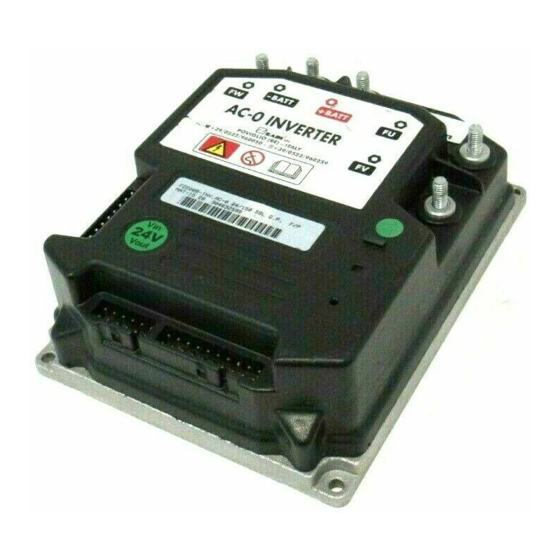
7 DRAWINGS 7.1 Mechanical drawing AC-0 INVERTER ZAPI PRODUCTION DATA Voltage Reference Figure 7–1 AE0ZP0EC - AC-0 SSL SENSORED - User Manual Page - 29/100... -
Page 30: Connection Drawing - Traction Configuration
7.2 Connection drawing – Traction configuration 7.2.1 Standard version with Encoder Figure 7–2 Page - 30/100 AE0ZP0EC - AC-0 SSL SENSORED - User Manual... -
Page 31: Mdi-Prc Version With Encoder
7.2.2 MDI-PRC Version with Encoder Figure 7–3 AE0ZP0EC - AC-0 SSL SENSORED - User Manual Page - 31/100... -
Page 32: Connection Drawing - Pump Configuration
7.3 Connection drawing – Pump configuration Figure 7–4 Page - 32/100 AE0ZP0EC - AC-0 SSL SENSORED - User Manual... -
Page 33: One Shot Installation Procedure
5) to handle a pump contactor 6) to handle a belly switch and an Inching operative mode 7) to handle the communication via CAN Bus with our MDI-PRC or other Zapi controllers 8) to handle a proportional input for the forks lifting/lowering You must fill your I/O equipment with your optional functions. -
Page 34: Sequence For Ac Traction Inverter Setting
When the "Key Switch" is closed, if no alarms or errors are present, the Console Display will be showing the Standard Zapi Opening Display (Home Display). For the setting of your truck, use the procedure below. If you need to reply the same setting on different controller, use the Save and Restore sequence as described in the 10.1 and 10.2 paragraphs. -
Page 35: Pump Configuration
Can see also the Figure 9–7 for details on the settings. Depending on the motor used it is necessary to set some parameters: giving Zapi the motor curves it is possible to know the optimal setting in order to the motor runs efficiently. - Page 36 Can see also the Figure 9–7 for details on the settings. Depending on the motor used it is necessary to set some parameters: giving Zapi the motor curves it is possible to know the optimal setting in order to the motor runs efficiently.
-
Page 37: Programming & Adjustments Using Digital Console
9.2 Description of console (hand set) & connection Figure 9–1 Digital consoles used to communicate with AC inverter controllers must be fitted with EPROM CK ULTRA, minimum "Release Number 3.02". AE0ZP0EC - AC-0 SSL SENSORED - User Manual Page - 37/100... -
Page 38: Description Of Standard Console Menu
The section describes the Zapi hand set functions. Numbers inside the triangles correspond to the same number on the hand set keyboard buttons shown in the Figure 9–1. The orientation of the triangle indicates the way to the next function. - Page 39 MDI PRC Version Figure 9–3 AE0ZP0EC - AC-0 SSL SENSORED - User Manual Page - 39/100...
-
Page 40: Pump Configuration
9.3.2 Pump configuration Figure 9–4 Page - 40/100 AE0ZP0EC - AC-0 SSL SENSORED - User Manual... -
Page 41: Function Configuration
This input must be connected to a Key voltage. The SR#2 becomes active when CNA#14 is opened. The inching forward becomes active when the CNA#14 is closed to a key voltage. AE0ZP0EC - AC-0 SSL SENSORED - User Manual Page - 41/100... - Page 42 If this option is programmed ON the traction inverter manages an hydraulic steering function when the "key" is switched ON (only if the AUX OUTPUT #1 option is programmed as HYDRO CONTACTOR or as EXCLUSIVE HYDRO). Page - 42/100 AE0ZP0EC - AC-0 SSL SENSORED - User Manual...
- Page 43 When there is also a switch connected to the pedal braking (i.e. SET INPUT #4 to level BRAKE), it must be closed, otherwise the release braking is stuck to the minimum strength disregarding the pedal potentiometer AE0ZP0EC - AC-0 SSL SENSORED - User Manual Page - 43/100...
- Page 44 Lowering). The CNB#9 input is the Lifting request to enable the pump contactor on CNA#4. The CNB#8 input is the Lowering request to enable the descent valve on CNA#6. Page - 44/100 AE0ZP0EC - AC-0 SSL SENSORED - User Manual...
- Page 45 (MDI-PRC version only). This option specifies the Electrovalve #2 type. The EVP2 is connected on the pin 9 of the MDI-PRC. OPTION #1: EVP2 is an On/Off valve. OPTION #2: EVP2 is a proportional valve AE0ZP0EC - AC-0 SSL SENSORED - User Manual Page - 45/100...
- Page 46 10) ADJUST BATTERY Fine adjustment of the battery voltage measured by the controller. 11) THROTTLE 0 ZONE It establishes a deadband in the accelerator input curve (see also paragraph Page - 46/100 AE0ZP0EC - AC-0 SSL SENSORED - User Manual...
- Page 47 Controller HourMeter plus this offset. This offset value is 5 Digits with: OPTION 05 is the MSDigit OPTION 01 is the LSDigit It is possible to change this offset only when the controller HourMeter is less AE0ZP0EC - AC-0 SSL SENSORED - User Manual Page - 47/100...
-
Page 48: Pump
OPTION #2: an analog motor thermal sensor (KTY84) is connected to A13 input. NONE: no motor thermal sensor switch is connected. 4) HOUR COUNTER This option specifies the hour counter mode. It can be set one of two: Page - 48/100 AE0ZP0EC - AC-0 SSL SENSORED - User Manual... - Page 49 4) MAX LOWER Not used. 5) MOTOR OVERTEMP With this setting, it is possible to raise a warning when the motor temperature overtakes a threshold specified by the MOTOR OVERTEMP value. AE0ZP0EC - AC-0 SSL SENSORED - User Manual Page - 49/100...
- Page 50 16) CHECK UP TYPE It specifies the handling of the CHECK UP NEEDED warning: NONE: No CHECK UP NEEDED warning. OPTION #1: CHECK UP NEEDED warning on the hand set after 300 Page - 50/100 AE0ZP0EC - AC-0 SSL SENSORED - User Manual...
- Page 51 Equal to OPTION#2 but the truck definitively stops after 380 hours. 17) OPTION 05 Not used. 18) OPTION 04 Not used. 19) OPTION 03 Not used. 20) OPTION 02 Not used. 21) OPTION 01 Not used. AE0ZP0EC - AC-0 SSL SENSORED - User Manual Page - 51/100...
- Page 52 CONFIG MENU The Display will show: SET OPTIONS SET OPTIONS Press OUT again. Display now will show the ' ' ' ' % ' opening Zapi menu. Figure 9–5 Page - 52/100 AE0ZP0EC - AC-0 SSL SENSORED - User Manual...
- Page 53 Press OUT ' % ' ' % ' Press ENTER to confirm ' ' ' Repeat the same from 5 to 12 points for the other adjustment Figure 9–6 AE0ZP0EC - AC-0 SSL SENSORED - User Manual Page - 53/100...
-
Page 54: Parameter Regulation
9.5 Parameter regulation In addition to the input configuration, parameter modification is made directly by ZAPI on customer specifications, or by the customer, making the adjustments using the programming console. 9.5.1 Traction The following parameters can be modified: 1) ACCELER. DELAY Level 0 to 9. - Page 55 TYPE in “Set options” submenu for the handling). 20) MAX VALVE 1 (MDI-PRC version only). 0 to 255 digit. This parameter determines the maximum voltage applied on the EVP1 when the position of the AE0ZP0EC - AC-0 SSL SENSORED - User Manual Page - 55/100...
- Page 56 PRC) in the opening transition (if proportional); this is the time necessary to go from the minimum to the maximum voltage. If the electrovalve is programmed like an On/Off valve this parameter is not effective. Page - 56/100 AE0ZP0EC - AC-0 SSL SENSORED - User Manual...
- Page 57 This parameter can be adjusted from 1 to 255 with regulation of 1digit MAX VALVE 2 This parameter can be adjusted from 1 to 255 with regulation of 1digit AE0ZP0EC - AC-0 SSL SENSORED - User Manual Page - 57/100...
-
Page 58: Pump
(SR on CNB#8) is active. When set to 100% the speed reduction is ineffective. 10) FREQUENCY CREEP Hz value. This is the minimum speed applied when lifting (LIFT ENABLE on Page - 58/100 AE0ZP0EC - AC-0 SSL SENSORED - User Manual... - Page 59 Time units value (seconds). It determines the time delay when an hydraulic steering function request is switched off. The following table shows the different values at which the parameters can be set. AE0ZP0EC - AC-0 SSL SENSORED - User Manual Page - 59/100...
- Page 60 (***) Adjustable with a 1 Hz resolution in the 0 to 200 Hz range. Page - 60/100 AE0ZP0EC - AC-0 SSL SENSORED - User Manual...
- Page 61 YES=ENTER NO=OUT Press ENTER to accept the changes, or press OUT ' ' ' ' % ' to discard them. MAIN MENU The Display will show PARAMETER CHANGE Figure 9–7 AE0ZP0EC - AC-0 SSL SENSORED - User Manual Page - 61/100...
-
Page 62: Zapi Menu "Hardware Settings" Functions List
9.5.3 Zapi menu “HARDWARE SETTINGS” functions list Confidential documentation. Page - 62/100 AE0ZP0EC - AC-0 SSL SENSORED - User Manual... -
Page 63: Zapi Menu "Special Adjustments" Functions List
9.5.4 Zapi menu “SPECIAL ADJUSTMENTS” functions list Note: the below set-up description is for skilled persons only: if you aren’t please keep your hands off. To enter this Zapi hidden menu a special procedure is required. Ask, this procedure, directly to a Zapi technician. -
Page 64: Main Menu "Tester" Functions List
10) TEMPERATURE °C value. This is the temperature of the inverter base plate. This temperature is used for the HIGH TEMPERATURE alarm detection (see 11.1.7.1). Page - 64/100 AE0ZP0EC - AC-0 SSL SENSORED - User Manual... - Page 65 When CNA#15 is closed to a battery (key) voltage the Aux Lowering request is active. OFF GND = When CNA#15 is not closed to a battery (key) voltage (or AE0ZP0EC - AC-0 SSL SENSORED - User Manual Page - 65/100...
- Page 66 SET INPUT#4 is set BRAKE: QUICK INVERSION reading becomes ON when the brake pedal switch closes and connects the CNB#7 input to a key voltage. SET INPUT#4 is set EX. HYDRO: Page - 66/100 AE0ZP0EC - AC-0 SSL SENSORED - User Manual...
-
Page 67: Pump
2) MOTOR VOLTAGE Percentage value. It is the voltage generated by the inverter expressed in per cent of the actual battery voltage. 100% means the sine wave width is close AE0ZP0EC - AC-0 SSL SENSORED - User Manual Page - 67/100... - Page 68 ON/OFF. This is the level of the CNB#5 digital input (first speed request): ON +VB = When CNB#5 is closed to a battery (key) voltage, the first speed request is active. Page - 68/100 AE0ZP0EC - AC-0 SSL SENSORED - User Manual...
- Page 69 In this case Exclusie hydro is the level of the CNB#7 digital input (Hydro steering switch): ON GND = When CNB#7 is not connected to a battery (key) voltage (or it is connected to GND) the hydraulic steering function AE0ZP0EC - AC-0 SSL SENSORED - User Manual Page - 69/100...
- Page 70 OFF +VB= When CNB#7 is closed to a battery (key) voltage the hydraulic steering function is not active. Page - 70/100 AE0ZP0EC - AC-0 SSL SENSORED - User Manual...
-
Page 71: Other Functions
You can see the items that are being stored whilst READING … ACCEL. DELAY (ECC.) the SAVE routine is happening SELECT: MOD. 01 When finished, the Console shows: FREE AE0ZP0EC - AC-0 SSL SENSORED - User Manual Page - 71/100... - Page 72 ' ' ' Press OUT to return to the Opening Zapi Display ' % ' NOTE: in reality the SAVE and RESTORE function requires the Windows PC- Console. Page - 72/100 AE0ZP0EC - AC-0 SSL SENSORED - User Manual...
-
Page 73: Description Of Console "Restore" Function
Press ENTER for YES, or OUT for No ' ' ' ' % ' You can see the items that are being stored in the STORING chopper memory whilst the RESTORE routine is ACCELER. DELAY happening AE0ZP0EC - AC-0 SSL SENSORED - User Manual Page - 73/100... - Page 74 MAIN MENU When finished, the Console shows: RESTORE PARAM. ' ' ' Press OUT to return to the Opening Zapi Display ' % ' NOTE: in reality the SAVE and RESTORE function requires the Windows PC- Console. Page - 74/100...
-
Page 75: Description Of Console "Program Vacc" Function
It enables compensation for non symmetry of the mechanical system between directions. The operation is performed by operating the pedal after entering the PROGRAM VACC function. AE0ZP0EC - AC-0 SSL SENSORED - User Manual Page - 75/100... - Page 76 Press ENTER for yes, or OUT for NO ' % ' MAIN MENU When finished, the Console shows: PROGRAM VACC ' ' ' Press OUT to return to the Opening Zapi Display ' % ' Page - 76/100 AE0ZP0EC - AC-0 SSL SENSORED - User Manual...
-
Page 77: Shortform Table Of The Aux Output #1 Setting (Traction Version)
EXCL. -Drives the coil The truck is not electrically hold on a slope, HYDRO of a hydraulic but comes down very slowly till the flat is steering reached. contactor. AE0ZP0EC - AC-0 SSL SENSORED - User Manual Page - 77/100... -
Page 78: Description Of The Throttle Regulation
(see Figure 10– 2 below) to match the full speed in the truck with the MAX VACC voltage in the accelerator position. Figure 10–2 Page - 78/100 AE0ZP0EC - AC-0 SSL SENSORED - User Manual... -
Page 79: Description Of The Battery Charge Detection Setting
(e.g. if the Battery Discharged Detection occurs when the battery is not totally discharged, it is necessary to reduce the ADJUSTMENT #02 setting as indicated in the Figure 10–3 below). Figure 10–3 AE0ZP0EC - AC-0 SSL SENSORED - User Manual Page - 79/100... -
Page 80: Alarms List - Traction Configuration
Try to execute a CLEAR EEPROM operation. This consists of Entering the ALARMS item in the MAIN MENU. Push at the same time the two right side buttons to enter the hidden ZAPI MENU. Roll up and Down until the CLEAR EEPROM appears on the hand set display. -
Page 81: Two Blinks Alarms
(e.g. when the pump inrush current makes the battery temporary collapsed). So first of all check for your failure mode then contact the Zapi technician to look for a countermeasure. As a matter of fact this alarm may occurs also for a HW failure and, in this case, it is necessary to replace the Controller. -
Page 82: Three Blinks Alarms
- Remedy: Three possibilities: - Another device, connected in parallel with the Rail Capacitors, has a failure - At least a motor phase is not connected to the controller or Page - 82/100 AE0ZP0EC - AC-0 SSL SENSORED - User Manual... -
Page 83: Four Blinks Alarms
The SW continuously checks for the connection of the two supply ends of the potentiometer in the accelerator. The test consists of reading the voltage drop on a sense diode, AE0ZP0EC - AC-0 SSL SENSORED - User Manual Page - 83/100... -
Page 84: Five Blinks Alarms
Frequently we experienced one of the two Sensor bearing’s ring, slips inside its seat raising this alarm condition. Also the electromagnetic noise on the sensor bearing can be a Page - 84/100 AE0ZP0EC - AC-0 SSL SENSORED - User Manual... -
Page 85: Six Blinks Alarms
The controller checks if the MC contact is closed when the coil isn’t driven, trying to discharge the capacitor bank. If they don’t discharge, the fault condition is entered. AE0ZP0EC - AC-0 SSL SENSORED - User Manual Page - 85/100... - Page 86 See 11.2 and the manual of the MDI-PRC. 10) MDI DRV 2 OPEN MDI-PRC Code = 75 - Cause: This alarm occurs on the MDI-PRC and the information is Page - 86/100 AE0ZP0EC - AC-0 SSL SENSORED - User Manual...
-
Page 87: Seven Blinks Alarms
CAN Bus and check if this alarm disappears. When you are quite sure the problem is in the present module, it is necessary to replace the controller. AE0ZP0EC - AC-0 SSL SENSORED - User Manual Page - 87/100... -
Page 88: No Blink Alarms
Then it is necessary to specify if the controller is AC-0 or AC-1 type (see AC TYPE 0 in the hidden hardware setting Zapi menu). If the alarm is present, by switching off the key the AC TYPE 0 setting will be turned automatically On (and the controller is specified to be an AC-0). -
Page 89: Mdi-Prc "Alarms" List
WRONG SET BATT. CHECK UP NEEDED The Alarm Code List Sourced by the MDI-PRC (Source Device Code 16) is the following: CAN BUS KO The Can Bus communication is broken AE0ZP0EC - AC-0 SSL SENSORED - User Manual Page - 89/100... - Page 90 MDI NEVP1 NOT OK At least one Proportional Valve driver on pin#8 and #9 is shorted Example: 02A79 is an INCORRECT START alarm on the AC-0 traction controller. Page - 90/100 AE0ZP0EC - AC-0 SSL SENSORED - User Manual...
-
Page 91: Alarms List - Pump Configuration
Try to execute a CLEAR EEPROM operation. This consists of Entering the ALARMS item in the MAIN MENU. Push at the same time the two right side buttons to enter the hidden ZAPI MENU. Roll up and Down until the CLEAR EEPROM appears on the hand set display. -
Page 92: Two Blinks Alarms
(e.g. when the pump inrush current makes the battery temporary collapsed). So first of all check for your failure mode then contact the Zapi technician to look for a countermeasure. As a matter of fact this alarm may occurs also for a HW failure and, in this case, it is necessary to replace the Controller. -
Page 93: Four Blinks Alarms
The test consists of reading the voltage drop on a sense diode, connected between NPOT (CNB#11) and GND and cascaded with the potentiometer: if the potentiometer gets disconnected on PPOT AE0ZP0EC - AC-0 SSL SENSORED - User Manual Page - 93/100... -
Page 94: Five Blinks Alarms
- Remedy: Check the coils of the main contactor (CNA#1) and of the first (CNA#3), the second (CNA#4) and the third (CNA#6) auxiliary outputs. Page - 94/100 AE0ZP0EC - AC-0 SSL SENSORED - User Manual... - Page 95 Braked (probably the Driver of the Electromechanical Brake is opened) and this alarm occurs. - Remedy: Probably it is necessary to replace the controller because the driver of the Electromechanical Brake has a failure. AE0ZP0EC - AC-0 SSL SENSORED - User Manual Page - 95/100...
-
Page 96: Seven Blinks Alarms
Then it is necessary to specify if the controller is AC-0 or AC-1 type (see AC TYPE 0 in the hidden hardware setting Zapi menu). If the alarm is present, by switching off the key the AC TYPE 0 setting will be turned automatically On (and the controller is specified to be an AC-0). -
Page 97: Thirty Two Blinks Alarms
- Remedy: The maximum current set-up is factory adjusted and so this alarm never should happen when the controller is on the field. So ask for the assistance of a Zapi technicians when this alarm occurs. 12.1.10 Thirty Two Blinks Alarms... - Page 98 VACC NOT OK INCORRECT START PEDAL WIRE KO CURRENT SENS KO WRONG SET BATT. CHECK UP NEEDED Example: 05A79 is an INCORRECT START alarm on the AC-0 Pump controller. Page - 98/100 AE0ZP0EC - AC-0 SSL SENSORED - User Manual...
- Page 99 Description C29508 SW 180 24V Single Pole Contactor C12407 Molex Minifit Connector 12 pins Female C12408 Molex Minifit Connector 20 pins Female C12777 Female Molex Minifit pin harness side AE0ZP0EC - AC-0 SSL SENSORED - User Manual Page - 99/100...
- Page 100 The installation of this electronic controller should be made according to the diagrams included in this Manual. Any variations or special requirements should be made after consulting a Zapi Agent. The supplier is not responsible for any problem that arises from wiring methods that differ from information included in this Manual.
Need help?
Do you have a question about the AC-0 SSL and is the answer not in the manual?
Questions and answers