Doms PSS 5000 Technical Manual
Hide thumbs
Also See for PSS 5000:
- Technical manual (152 pages) ,
- Hardware configuration manual (55 pages) ,
- Product manual (33 pages)
Table of Contents
Advertisement
Quick Links
Download this manual
See also:
Installation Manual
Advertisement
Table of Contents

Related Manuals for Doms PSS 5000


Summary of Contents for Doms PSS 5000
- Page 1 PSS 5000 Technical Manual Date October 31, 2014 Document number PSS5000/TEMA/803046/14 Doms ApS Formervangen 28 Tel. +45 4329 9400 info@doms.dk DK-2600 Glostrup Fax. +45 4343 1012 www@doms.com...
-
Page 2: Legal Notices
Legal Notices Copyright Statement This Doms documentation is owned by Doms or its licensors and is protected. Your right to use this documentation is subject to the limitations and restric- tions imposed by applicable licenses and copyright laws. Unauthorized repro- duction, modification, distribution, display or other use of this documentation may result in criminal and civil penalties. - Page 3 PSS 5000 Hardware ........
- Page 4 PSS 5000 – Technical Manual Contents Protocol to Port Assignment (Menu 2.1) ..... . . 35 5.1.1 Changing Protocol to Port Assignments ....36 5.1.2...
- Page 5 Referenced Documents ........143 PSS 5000 XML Output ........144 Accessing the XML Files .
- Page 6 PSS 5000 – Technical Manual Contents Config.xml File ......... . 145 Site_sta.xml File .
-
Page 7: Part I: Getting To Know The Pss 5000
PSS 5000 – Technical Manual Part I: Getting to Know the PSS 5000 Part I: Getting to Know the PSS 5000 ‘1 Architectural Overview’ on page 8 • ‘2 System Description’ on page 11 • ‘3 Configuration and Service’ on page 21 •... -
Page 8: Architectural Overview
PSS 5000 – Technical Manual 1 Architectural Overview Architectural Overview List of PSS 5000 The PSS 5000 can be used in 3 basic configurations. These are described in the configurations following topics: • ‘1.1 PSS 5000 Without a Network Connection’ on page 8 •... -
Page 9: Pss 5000 With A Network Connection
1 Architectural Overview PSS 5000 With a Network Connection Illustration of a system This illustration shows how POS terminals can be used by connecting them to using an Ethernet the PSS 5000 using an Ethernet connection. network PSS5000/TEMA/803046/14 9 of 155... -
Page 10: Pss 5000 In A Mixed Configuration
PSS 5000 – Technical Manual 1 Architectural Overview PSS 5000 in a Mixed Configuration Illustration of a system This illustration shows how POS terminals can be used through a serial POS using both an Ethernet driver even when an Ethernet connection is present. -
Page 11: System Description
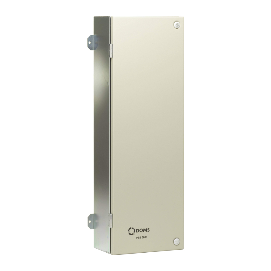
PSS 5000 – Technical Manual 2 System Description System Description List of PSS 5000 The basic components of the PSS 5000 are described in the following topics: components • ‘2.1 PSS 5000 Hardware’ on page 11 • ‘2.2 PSS 5000 Software’ on page 16... - Page 12 The external label On the outside of the cabinet, located above the power input socket, is a label. This label provides the serial number of the PSS 5000 and informs you which power supply voltage the PSS 5000 can use.
-
Page 13: Pss 5000 Computer Processor Boards
PSS 5000 – Technical Manual 2 System Description 2.1.2 PSS 5000 Computer Processor Boards PSS 5000 CPU Board The product specifications for the CPU boards of the PSS 5000 are presented specifications in the table below: Parameters CPU Board Version... -
Page 14: Hardware Interface Modules
PSS 5000 – Technical Manual 2 System Description Service Port Cable The Service Port is used to connect a PC to the PSS 5000 when access via the Connections Ethernet port is not possible. In such circumstances, it is necessary to use a... -
Page 15: Service And Maintenance
PSS 5000 – Technical Manual 2 System Description Illustration of HIMs Examples of a DSB HIM and a DMB HIM are shown below. Note: The black serial connectors on the DMB modules are wider than those on the DSB models. This extra width is a result of more pins, which are required for the signals used to control the onboard multiplexer. -
Page 16: Pss 5000 Software
‘2.2.7 Network Connection’ on page 20 2.2.1 Virtual File System Structure of virtual file The PSS 5000 has a UNIX inspired virtual file system, with the following top- system level structure: Description of the virtual Each of the catalogs present in the virtual file system are described in the table... -
Page 17: Memory Structure
2.2.2 Memory Structure Memory areas on the The memory on the PSS 5000 CPU board is divided in to 4 areas. CPU board The difference between the separate memory areas is indicated by what is re- quired to clear or change the data. -
Page 18: The Software Components
2.2.3 The Software Components List of PSS 5000 The software components of the PSS 5000 comprises 3 separate binary pro- software components gram blocks. Each block is loaded separately and comes complete with its own check sum. The blocks are: •... -
Page 19: Web Server
PSS 5000 – Technical Manual 2 System Description rity of the data and make sure that the PSS 5000 is operating correctly and complies to the legal requirements. The LAM ID has the program type ID: 498-BB-VVV The program branch number (BB) normally is associated with a country or re- gion. -
Page 20: Serial Server
2 System Description Illustration of an FTP This illustrates how to access the file system in a PSS 5000 using a web brows- connection to file system er and an FTP connection. The FTP connection to the PSS 5000 is made by in PSS 5000 FTP://admin:password@<IP address>... -
Page 21: Configuration And Service
Methods to access There are 2 methods to access the service menus that enable you to configure menus and monitor the PSS 5000. Information about the access tools are described in the following topics: • ‘3.1.1 Local Service Panel’ on page 21 •... -
Page 22: Pss5000/Tema/803046/14
PSS 5000 – Technical Manual 3 Configuration and Service Functions of the In general, the navigation buttons are used as follows: navigation buttons Buttons Description These buttons are used in the following ways: • To move down and up through the structure of the service menus. -
Page 23: Pss5000/Tema/803046/14
PSS 5000 – Technical Manual 3 Configuration and Service Display cycles during The illustration below shows the Local Service Panel display messages and startup LEDs during the start up phase. LSP Display BOOT APPL Status (Blank) BOOT started, call LAM module, initialize LAM. -
Page 24: Pss5000/Tema/803046/14
CPU board is powered down. Viewing data in the Local Data stored in the PSS 5000 memory, such as Recent Transactions or Trans- Service Panel display action Log, can be viewed using the local service panel display. However, be- cause of the size of the display, it is important to understand how the data ap- pears and how it can be read. -
Page 25: Web Service
PSS 5000 – Technical Manual 3 Configuration and Service 3.1.2 Web Service Pages Web Service page start- When accessing the Web Service pages a user_id and password is required. up page For more information about user IDs and passwords, see ‘5.4.1 Password... -
Page 26: Software Changes
Changes to the Application Program and/or Legal Authority Module on the changes PSS 5000 board take place by uploading the software using the Web Service Menus (with a Java applet) or using an FTP connection. (FTP requires only a few commands). -
Page 27: Pss5000/Tema/803046/14
PSS 5000 when changing the software in the PSS 5000. Note: Before software can be uploaded, the PSS 5000 must be set in a state that allows the upload. ‘To upload software with the web service menus’ on page 60 ‘To upload software using FTP’... -
Page 28: Pss5000/Tema/803046/14
PSS 5000 – Technical Manual Part II: Using the Service Menus Note: The individual menu options available in the Service Menus depend on the functions present in the program applications installed in the fore- court controller. ‘4 Information (Menu 1)’ on page 29 •... -
Page 29: Information (Menu 1)
PSS 5000 – Technical Manual 4 Information (Menu 1) Information (Menu 1) Overview of Information Information menu is divided into the following sub-menus: menu • ‘4.1 Program Versions (Menu 1.1)’ on page 29 • ‘4.2 Board Info (Menu 1.2)’ on page 30 •... -
Page 30: Board Info (Menu 1.2)
View program versions The program version information is also available in the following files using using virtual file system the PSS 5000 Virtual File System. • /pss_proc/sys/boot_inf.txt – contains BOOT information • /pss_proc/sys/lam_inf.txt – contains Legal Authority Module information • /pss_proc/sys/appl_inf.txt – contains Application information Board Info (Menu 1.2) -
Page 31: Pss5000/Tema/803046/14
PSS 5000 – Technical Manual 4 Information (Menu 1) To view production This procedure describes how to use the Service Menu in the web browser to information with web view the production information for the CPU board. service pages ... -
Page 32: Sealing Switch (Menu 1.2.2)
Press the buttons in the sequence shown below to move to the sub-menus and view the production information for the PSS 5000. The serial number and production number shown in the display are unique for the CPU Board of the PSS 5000 you are currently viewing. 4.2.2 Sealing Switch (Menu 1.2.2) -
Page 33: Sw Blocks (Menu 1.3)
SW Blocks (Menu 1.3) To view software blocks Each application program in the PSS 5000 is built from several software code in PSS 5000 with web blocks. This procedure describes how to use the Service Menu in the web service pages browser to view the SW blocks (names, ID, version and checksum). -
Page 34: Protocols (Menu 1.4)
PSS 5000 – Technical Manual 4 Information (Menu 1) Protocols (Menu 1.4) To view available This procedure describes how to use the Service Menu in the web browser to protocols with web view the protocols that are supported and can be assigned. -
Page 35: Installation (Menu 2)
‘5.8 Backup (Menu 2.8)’ on page 65 Protocol to Port Assignment (Menu 2.1) Description of the The PSS 5000 application can use a large number of protocols with which to protocol to port communicate with the other system devices. assignment menu Generally, the serial interface supports only one protocol per port. -
Page 36: Changing Protocol To Port Assignments
PSS 5000 – Technical Manual 5 Installation (Menu 2) 5.1.1 Changing Protocol to Port Assignments To configure protocol to This procedure describes how to use the Service Menu in the web browser to port assignment with configure the protocol to port assignment values. -
Page 37: Pss5000/Tema/803046/14
- restores all the Protocol to Port assignments to their original values. In the confirmation window, click The changes are saved and the PSS 5000 is Master Reset. To edit a protocol to port This procedure describes how to use the Service Menu in the web browser to assignment with web edit a protocol to port assignment. -
Page 38: Pss5000/Tema/803046/14
PSS 5000 – Technical Manual 5 Installation (Menu 2) To add a protocol to Port This procedure describes how to use the Service Menu in the web browser to 41 or Port 99 with web add/change the protocol to port assignment values for Port 41 or Port 99. -
Page 39: Setting The Protocol Parameter Values
PSS 5000 – Technical Manual 5 Installation (Menu 2) Click Protocol to Port Assignment The page returns to the list; go to ‘To configure protocol to port assignment with web service pages’ on page 36, Step 2. Note: Protocol to... -
Page 40: Limitations
Note: Discard Changes If you do not wish to apply the changes, click In the confirmation window, click The changes are saved and the PSS 5000 is Master Reset. 5.1.3 Limitations List of areas with Not all protocol to port assignments are possible. There can be a number of limitations reasons why an assignment is not possible. -
Page 41: Date And Time (Menu 2.2)
Date and Time (Menu 2.2) Description of Date and The PSS 5000 has it's own Real Time Clock (RTC), which is used to time Time menu stamp various events. The RTC setting can be changed via the Web, the Local Service Panel and in some applications via the POS Protocol. -
Page 42: Communication Setup (Menu 2.3)
PSS 5000 – Technical Manual 5 Installation (Menu 2) Press the buttons in the sequence shown below to move to the sub-menus and view/change the date and time values in the PSS 5000. Communication Setup (Menu 2.3) Overview of Configuration Setup... -
Page 43: Tcp/Ip Setup (Menu 2.3.1)
PSS 5000 – Technical Manual 5 Installation (Menu 2) 5.3.1 TCP/IP Setup (Menu 2.3.1) Description of TCP/IP Configuration of the TCP/IP parameters must be done in accordance with the Setup menu IP address plan for the location. In order to avoid conflicts with other network devices, consult your network administrator regarding this subject. -
Page 44: Pss5000/Tema/803046/14
5 Installation (Menu 2) To view/change the This procedure describes how to use the Service Menu in the web browser to TCP/IP setup with web view/change the values for the TCP/IP setup parameters in the PSS 5000. service pages ... -
Page 45: Pss5000/Tema/803046/14
TCP/IP SETUP 2.3.1 Press to move to the menu. Press the buttons in the sequence shown below to move to the sub-menus and view the MAC address of the Ethernet module in the PSS 5000. PSS5000/TEMA/803046/14 45 of 155... -
Page 46: Service Port Setup (Menu 2.3.2)
The values underlined are the default values. To view/change the This procedure describes how to use the Service Menu in the web browser to Service Port setup with view/change the values for the Service Port Setup in the PSS 5000. web service pages ... -
Page 47: Datalink Timeout For Serial Driver (Menu 2.3.3)
Press the buttons in the sequence shown below to move to the sub-menus and view/change the baud rate and the PPP device values in the PSS 5000. Note: The current setting is flashing in each of the sub-menus. -
Page 48: Service Port Protocol (Menu 2.3.4)
The new value is effective after the board is reset. To view/change the This procedure describes how to use the Local Service Panel to view/change Datalink Timeout with the values of the Datalink Timeout for the serial driver in the PSS 5000. local service panel INFORMATION 1 Press to move to the menu. -
Page 49: Menu 2.3.5 – Reserved For Future Use
Dialup Setup/Test menu enables you to set up the communication param- Setup/Test eters for a modem connected to one of the DMB ports in the PSS 5000. Before the dialup connection can work, the following parameters must be defined: Parameter... -
Page 50: Online/Offline Event Time (Menu 2.3.7)
PSS 5000 – Technical Manual 5 Installation (Menu 2) 2 Installation 2.3 Communication Setup 2.3.6 Dialup Setup/Test Select Dialup Settings page appears. Select the Baud rate value that matches your system. Select the PPP device value that matches your system. -
Page 51: System Profile (Menu 2.4)
5 Installation (Menu 2) To view/change the This procedure describes how to use the Service Menu in the web browser to Online/Offline Event view/change the values for the Online/Offline Event Timer in the PSS 5000. Time with web service ... -
Page 52: Pss5000/Tema/803046/14
PSS 5000 – Technical Manual 5 Installation (Menu 2) Note: When a Super Master Reset takes place on the PSS 5000, all the pass- words are reset to their default settings. User Description admin This is used by the PSS system administrator and has all privileges: •... -
Page 53: Pss5000/Tema/803046/14
In the field, re-type the password given in Step Click to save the changes. A message appears which confirms that the password was changed and tells you to log off and reconnect to the PSS 5000. PSS5000/TEMA/803046/14 53 of 155... -
Page 54: Pss5000/Tema/803046/14
"Doms password of the day". This password has 4 HEX characters (0– 9, A–F) and can be obtained by contacting Doms Support. The PSS 5000 has a password validation routine in the Legal Authority Mod- ule with fixed user_id/password combinations. The default password for all users is "password". -
Page 55: Name And Number (Menu 2.4.2)
Name and Number (Menu 2.4.2) To change the system This procedure describes how to use the Service Menu in the web browser to name and number change the system name and number for the PSS 5000. 2 Installation 2.4 System Profile... -
Page 56: Web Preferences (Menu 2.4.4)
You can include your own logo or graphic in the top left-hand cor- ner of the service menu pages, and you can change the rate by which informa- tion in the Operational Status web pages is updated from the PSS 5000. To change the web... -
Page 57: Pss5000/Tema/803046/14
PSS 5000 – Technical Manual 5 Installation (Menu 2) 2 Installation 2.5 Application Software Select Application Setup page appears. Select Setup Group Setup Group? In the table, open the drop-down list. Select one of the following: Forecourt Control Setup •... -
Page 58: Software Upload (Menu 2.6)
PSS 5000 – Technical Manual 5 Installation (Menu 2) Wet Stock Setup New Setup In the page, select the required radio button. Note: On should be selected if delivery information is required but the sys- tem does not contain a POS that is capable of clearing the delivery report. -
Page 59: Pss5000/Tema/803046/14
Setting the PSS 5000 to accept software uploads is enabled using either the web service pages or the local service panel. -
Page 60: Pss5000/Tema/803046/14
5 Installation (Menu 2) To upload software with This procedure describes how to use the Service Menu in the web browser to the web service menus upload software to the PSS 5000. Note: Before you start this procedure, read ‘Important information about BOOT and LAM software’... -
Page 61: Pss5000/Tema/803046/14
Type in the correct information for the following fields: User name • – PSS 5000 user name Password • – password for PSS 5000 user name Log text • – additional text to help identify the upload Files • – location and file name of software you want to upload Backup PSS •... -
Page 62: Pss5000/Tema/803046/14
To upload software using This procedure describes how to use FTP to upload software to the PSS 5000. The commands used in this procedure use FileZilla to illustrate the commands. However, other FTP clients may be used. -
Page 63: Peripheral Configuration (Menu 2.7)
To overcome limitations in some POS interfaces, a set-up file (setup.ini which, file using FTP for example, contains device pre-configuration) can be uploaded. The set- up.ini file can be downloaded from and/or uploaded to the PSS 5000 using any FTP client (WP_FTP, CuteFTP) or from a command line using ftp.exe. Note: If a device item is pre-configured in the setup.ini file, the specified value... -
Page 64: Memory Module (Menu 2.7.1)
From the menu you can configure the number of memory Module menu modules installed in the PSS 5000. This menu is only available using the local service panel. To configure the number The number of memory modules, also known as peripheral devices, can be of memory modules with configured using the local service panel. -
Page 65: Backup (Menu 2.8)
PSS 5000 – Technical Manual 5 Installation (Menu 2) Note: This prepares the PSS 5000 for the new setup.ini file, which is not deleted during a Master Reset. Syntax errors in the setup.ini file are reported in the file /pss_proc/sys/bel.txt. -
Page 66: Pss5000/Tema/803046/14
The path to the selected setup.ini file appears in the field. Click The setup.ini file is now copied to /pss_mem/2/appl/ on the PSS 5000. Perform a Master Reset on the PSS 5000 to activate the parameter values in the new setup.ini file. 66 of 155 PSS5000/TEMA/803046/14... -
Page 67: Operation (Menu 3)
‘6.9 Reconciliation Report (Menu 3.9)’ on page 75 Enter Fallback Mode (Menu 3.1) Description of fallback With the PSS 5000, there is an option to operate in Attendant Fallback Mode. mode menu In this mode, the PSS system internally authorizes each pump when a nozzle is lifted and clears transactions without involving any external POS or OPT device. -
Page 68: Pss5000/Tema/803046/14
Fallback Mode Select Click The PSS 5000 is now in Fallback mode and will remain there until an op- erational POS forces it back to normal operation. To set Fallback Mode This procedure describes how to use the Local Service Panel to select the Fall- with local service panel back Mode in the PSS 5000. -
Page 69: Grade Prices (Menu 3.2)
To view/change grade This procedure describes how to use the Local Service Panel to view/change prices with local service the grade prices in the PSS 5000. panel Note: This function is not available for all Application Programs. -
Page 70: Fp Transactions (Menu 3.3)
PSS 5000 – Technical Manual 6 Operation (Menu 3) To change the prices for the remaining products, repeat Step 3. When you have changed the price for the last product, you are ready to update the pric- Press to set the new prices. -
Page 71: Log (Menu 3.3.2)
Description of Payment The Payment Server menu is used to control which cards that can be used on Server menu the site. Note: Not all versions of the PSS 5000 application software include the pay- ment server. PSS5000/TEMA/803046/14 71 of 155... -
Page 72: Operation Mode (Menu 3.5)
6 Operation (Menu 3) To check the validity of a Card Check menu enables you to check if a card is included in the white card list loaded in the PSS 5000. 3 Operation 3.4 Payment Server 3.4.1 Card Check... -
Page 73: Menu 3.6 Reserved For Future Use
Confirmation of the selected operation mode appears briefly on screen. Verify the values shown on screen are correct. Menu 3.6 Reserved for Future Use Reserved This menu is reserved for implementation of future features in the PSS 5000. PSS5000/TEMA/803046/14 73 of 155... -
Page 74: Operational Status (Menu 3.7)
Operational Status menu provides the current status of all the forecourt de- Operational Status menu vices connected to the PSS 5000. The status is updated automatically or, if necessary, can be updated manually. Note: The value for the automatic update period is defined in the Web Prefer- ences page, see ‘5.4.4 Web Preferences (Menu 2.4.4)’... -
Page 75: Teleterminal (Menu 3.8)
The Reconciliation Report page presents both Totalizer Readings and ATG Readings with start and stop time stamps. The Totalizer Readings are provided by the PSS 5000 and are metered sales values for each of the tanks associated with each fueling point. The ATG Readings are gauged tank volumes provided by the tank gauge system. -
Page 76: Pss5000/Tema/803046/14
Parameter Description Report Identifiers System name This is the id assigned to the PSS 5000. Number This shows which report is displayed. Note: If the Number value is equal to or greater than 7, then there are 7 reconciliation reports you can view. -
Page 77: Pss5000/Tema/803046/14
PSS 5000 – Technical Manual 6 Operation (Menu 3) Parameter Description Manual report creation A check box and Enable/Disable button that al- low you to activate/deactivate the Create Report button. Note: Both the check box and the button must be used to change the state of the Create Report button. -
Page 78: Pss5000/Tema/803046/14
PSS 5000. Note: Before reconciliation reports can be created by the PSS 5000, it is im- portant that the relationships between each of the fueling points and the associated tanks are configured in the PSS 5000. -
Page 79: Reset (Menu 4)
PSS 5000 – Technical Manual 7 Reset (Menu 4) Reset (Menu 4) Overview of Reset menu Reset menu is divided into the following sub-menus: • ‘7.1 Soft Reset (Menu 4.1)’ on page 79 • ‘7.2 Master Reset (Menu 4.2)’ on page 80 •... -
Page 80: Master Reset (Menu 4.2)
PSS 5000 – Technical Manual 7 Reset (Menu 4) SOFT RESET? Press to select the menu. Use the buttons to toggle between Select and press The system performs a soft reset. Master Reset (Menu 4.2) Description of a master A Master Reset will, in general, clear the configuration data for the Applica- reset tion, for example, the configuration data for Fuelling Points and Tank Gauges. -
Page 81: Super Master Reset (Menu 4.3)
PSS 5000 – Technical Manual 7 Reset (Menu 4) MASTER RESET? Press to select the menu. Press and hold for 10 seconds. OK MASTER RE- The system performs a master reset. The display shows SET... Super Master Reset (Menu 4.3) Description of a super The Super Master Reset simply clears all the memory. -
Page 82: Pss5000/Tema/803046/14
PSS 5000 – Technical Manual 7 Reset (Menu 4) SUPER M RESET? Press to select the menu. Press and hold for 10 seconds..SUPER The system performs a Super Master Reset and the display shows MASTER RESET 82 of 155... -
Page 83: Diagnostics (Menu 5)
PSS 5000 – Technical Manual 8 Diagnostics (Menu 5) Diagnostics (Menu 5) Overview of Diagnostics Diagnostics menu is divided into the following sub-menus: menu • ‘8.1 Forecourt Devices (Menu 5.1)’ on page 83 • ‘8.2 System Logs (Menu 5.2)’ on page 95 •... -
Page 84: Pss5000/Tema/803046/14
Use the list to see which devices are currently online. The columns contain the following information: Column Description Port The number of the port on the PSS 5000 CPB to which the devices are connected. Protocol List of protocols assigned to the port (see ‘5.1 Protocol to Port Assignment (Menu 2.1)’... -
Page 85: Device Errors (Menu 5.1.2)
PSS 5000 – Technical Manual 8 Diagnostics (Menu 5) 8.1.2 Device Errors (Menu 5.1.2) Description of Device Device Errors From the menu it is possible to view the latest error that has oc- Errors menu curred on each device and/or view the last error for a specific device. -
Page 86: Price Pole Test (Menu 5.1.3)
PSS 5000 – Technical Manual 8 Diagnostics (Menu 5) Device Id Open the drop-down list and select the ID for the specific device. DEVICE ID OK Click A table with the error details for this device appears. The example below shows the error details for a price pole. -
Page 87: Pss5000/Tema/803046/14
PSS 5000 – Technical Manual 8 Diagnostics (Menu 5) To start a price pole test This procedure describes how to use the Service Menu in the web browser to with web service pages test the price pole. 5 Diagnostics 5.1 Forecourt Devices... -
Page 88: Device Status (Menu 5.1.4)
PSS 5000 – Technical Manual 8 Diagnostics (Menu 5) UPDATE PRICES Click The prices are sent to the price pole and the updated prices appear on the price pole. To start a price pole test This procedure describes how to use the Service Menu in the local service pan- with local service panel el to start a price pole test. -
Page 89: Pss5000/Tema/803046/14
PSS 5000 – Technical Manual 8 Diagnostics (Menu 5) VRC Controller Open the drop-down list for the and select a device ID for the controller. DEVICE ID OK Click The most important Vapor Recovery Monitoring status information ap- pears. Refresh If required, click to update the data shown on this page. -
Page 90: Pss5000/Tema/803046/14
5.1.4.2 Specific Device Status page appears. Note: Device Type list includes only those device types that are con- nected to and available from the PSS 5000. Device Type In the list select the specific device type. 90 of 155 PSS5000/TEMA/803046/14... -
Page 91: Device Test (Menu 5.1.5)
Description Device Test The Special Vapor Recovery Monitoring functions for test and service can menu for VRC only be accessed when you are logged on to the PSS 5000 System as a VRC user. password Log in details: User name:... -
Page 92: Pss5000/Tema/803046/14
PSS 5000 – Technical Manual 8 Diagnostics (Menu 5) 5 Diagnostics 5.1 Forecourt Devices 5.1.5 Device Test 5.1.5.1 Select Vapour Recovery Monitoring Test page appears. Device Id Open the drop-down list and select the ID for the selected device type. -
Page 93: Pss5000/Tema/803046/14
The PSS 5000 replies with a message that informs you which function is activated. Device Test menu The PSS 5000 has a built-in text bank. This makes it possible to show different description for Terminal texts in the terminal’s display. The actual text in the text bank changes depend- Text Test ing on which application programs are installed. -
Page 94: Pss5000/Tema/803046/14
PSS 5000 – Technical Manual 8 Diagnostics (Menu 5) To view the available This procedure describes how to use the Service Menu in the web browser to terminal display texts view the terminal display texts available. with web service pages ... -
Page 95: System Logs (Menu 5.2)
LAM and application Log menu software were uploaded to the PSS 5000. Each record contains a date stamp, the software version number and an ID of the user who made the upload. To view the Upload Log... -
Page 96: Reset Logs (Menu 5.2.2)
PSS 5000 – Technical Manual 8 Diagnostics (Menu 5) Use the navigation buttons, & to move vertically and & move horizontally around the log data. For more details about viewing data, see ‘Viewing data in the Local Service Panel display’ on page Press to exit the log data. -
Page 97: Pss5000/Tema/803046/14
PSS 5000 – Technical Manual 8 Diagnostics (Menu 5) To view the Master This procedure describes how to use the Service Menu in the web browser to Reset Logs with web view the Master Reset logs. service pages ... -
Page 98: Pss5000/Tema/803046/14
PSS 5000 – Technical Manual 8 Diagnostics (Menu 5) To view the Super This procedure describes how to use the Service Menu in the web browser to Master Reset Logs with view the Super Master reset logs. web service pages ... -
Page 99: Application Log (Menu 5.2.3)
PSS 5000 – Technical Manual 8 Diagnostics (Menu 5) To view the Master This procedure describes how to use the Service Menu in the local service pan- Reset Log with local el to view the Master reset log. service panel... -
Page 100: Access Log (Menu 5.2.4)
PSS 5000 – Technical Manual 8 Diagnostics (Menu 5) To view the Application This procedure describes how to use the Service Menu in the local service pan- Log with local service el to view the Application Log. panel INFORMATION 1... -
Page 101: Board Error Log (Menu 5.2.5)
PSS 5000 – Technical Manual 8 Diagnostics (Menu 5) To view the Access Log This procedure describes how to use the Service Menu in the local service pan- with local service panel el to view the Access log. INFORMATION 1... -
Page 102: Communication (Menu 5.3)
Port Statistics (Menu 5.3.2) Description of Port Port Statistics menu provides data about the amount of traffic and the Statistics menu number of errors present on each of the ports on the PSS 5000 CPU board. 102 of 155 PSS5000/TEMA/803046/14... -
Page 103: Protocols (Menu 5.3.3)
8 Diagnostics (Menu 5) To view the Port This procedure describes how to use the Service Menu in the web browser to Statistics with web view the PSS 5000 statistics for the communication ports on the CPU board. service pages ... -
Page 104: Peep (Menu 5.4)
Application software. Peep (Menu 5.4) Description of the Peep The PSS 5000 has an embedded communication dump facility, which is called menu a peep. The peep can basically run in two different modes. These modes are described in the table below:... -
Page 105: Pss5000/Tema/803046/14
The Peeper Applet has a digital signature from VeriSign. This proves that it is an authentic Doms Java Applet. When the Applet is activated you are prompt- ed to accept the digital signature. This ensures that the peep files are written to the hard disk. -
Page 106: Pss5000/Tema/803046/14
PSS 5000 – Technical Manual 8 Diagnostics (Menu 5) Note: If you have not used this function previously, click to accept the digital signature when the security warning appears. Peeper The Java Applet starts and the page appears. Settings In the... -
Page 107: Test (Menu 5.5)
Restricted Do not use this menu item. The use of this menu item is restricted to software developers. The function forces the PSS 5000 to remain in the boot mode. This prevents the Application Program installed from starting. 8.5.3 GDB (Menu 5.5.3) Restricted Do not use this menu item. -
Page 108: Online List (Menu 5.6.1)
CPU board. pages Note: The items listed in this list are devices associated with the PSS 5000, for example a memory module. 5 Diagnostics 5.6 Peripherals... -
Page 109: Pss5000/Tema/803046/14
PSS 5000 – Technical Manual 8 Diagnostics (Menu 5) To view recent errors This procedure describes how to use the Service Menu in the web browser to with web service pages view which errors have occurred recently on the peripherals. -
Page 110: Memory Module (Menu 5.6.3)
To view status of the This procedure describes how to use the Service Menu in the web browser to memory module with view the status of the memory module(s) installed in the PSS 5000. web service pages ... -
Page 111: Pss5000/Tema/803046/14
PSS 5000 – Technical Manual 8 Diagnostics (Menu 5) Note: If multiple modules are installed, the details for each module appear in separate tables. To view errors on This procedure describes how to use the Service Menu in the web browser to specific peripherals with see where memory modules that have been installed previously were used. -
Page 112: Lam Version (Menu W.1)
Local Service Panel display, and see if the PSS 5000 reacts accordingly. By being able to do this and see the results, you can verify that no errors are present on any of the checking fa- cilities. -
Page 113: Lam Parameters (Menu W.2)
This procedure describes how to use the Local Service Panel to view the ver- with local service panel sion and checksum number of the LAM currently loaded in the PSS 5000. Note: It is assumed that the Idle menu is shown in the display. -
Page 114: Pss5000/Tema/803046/14
This procedure describes how to use the Local Service Panel to view the ver- with local service panel sion and checksum number of the LAM currently loaded in the PSS 5000. Note: It is assumed that the Idle menu is shown in the display. -
Page 115: Memory Module Version (Menu W.3)
Note: This menu is only relevant if the PSS 5000 is configured with at least one memory module and the memory module(s) must be configured in the setup.ini file. For information about configuring the file see ‘5.7 Peripheral Configuration (Menu 2.7)’... -
Page 116: Program Upload Log (Menu W.4)
The upload log menu provides a record of when the LAM and application soft- Log menu ware were uploaded to the PSS 5000. Each record contains a date stamp, the software version number and an ID of the user who made the upload. -
Page 117: Recent Transactions (Menu W.5)
To view Recent This procedure describes how to use the Local Service Panel to view all the Transactions data with data for recent transactions that have taken place in the PSS 5000. local service panel Note: It is assumed that the Idle menu is shown in the display. -
Page 118: Pss5000/Tema/803046/14
To view payment log This procedure describes how to use the Local Service Panel to view all the data with local service data for payments that have taken place in the PSS 5000. panel Note: It is assumed that the Idle menu is shown in the display. -
Page 119: Checking Devices (Menu W.7)
Menu. By simulating an error on an operational critical function you are pages able to make sure that the checking facility in the PSS 5000 registers the error and responds in the correct manner. ... -
Page 120: Display Error (Menu W.7.1)
Checking devices set OK The message appears. This informs you that the selected device now has a simulated error present. You are now able to check that the PSS 5000 has responded in the correct way. W.7 Checking Devices Select again. -
Page 121: Send Error Security Telegram (Menu W.7.2)
PSS 5000 must react accordingly. Return the checking device setting to before you leave the PSS 5000. Failure to do this will result in the PSS 5000 not operating correctly. 9.7.3 LAM Code Error (Menu W.7.3) -
Page 122: Rtc Error (Menu W.7.4)
PSS 5000 must react accordingly. Return the checking device setting to before you leave the PSS 5000. Failure to do this will result in the PSS 5000 not operating correctly. 9.7.4 RTC Error (Menu W.7.4) -
Page 123: Trans Memory (Menu W.7.5)
PSS 5000 must react accordingly. Return the checking device setting to before you leave the PSS 5000. Failure to do this will result in the PSS 5000 not operating correctly. 9.7.5 Trans Memory (Menu W.7.5) -
Page 124: Pss5000/Tema/803046/14
PSS 5000 – Technical Manual Part III: Reference Information ‘A File Formats in the PSS 5000’ on page 125 • ‘B Web Service Connections’ on page 129 • ‘C Virtual File System’ on page 134 • ‘D PSS 5000 Reference Information’ on page 141 •... -
Page 125: A File Formats In The Pss 5000
PSS 5000 – Technical Manual A File Formats in the PSS 5000 File Formats in the PSS 5000 Overview of file format File formats used in PSS 5000 are described in the following topics: information • ‘A.1 Recent Transactions File Format’ on page 125 •... -
Page 126: A.2 Transaction Log File Format
PSS 5000 – Technical Manual A File Formats in the PSS 5000 Transaction Log File Format Transaction Log file The figure below shows an example of a single line from a Transaction Log format (card payment) file. The data shows that it was a card payment transaction that occurred. -
Page 127: A.3 Upload Log File Format
PSS 5000 – Technical Manual A File Formats in the PSS 5000 The table below explains what is represented by the values in the different col- umns of the transaction data. Column Explanation W&M character. "¤" indicates that the security telegram is intact. -
Page 128: Pss5000/Tema/803046/14
PSS 5000 – Technical Manual A File Formats in the PSS 5000 Note: The name and location of the file is: /pss_mem/1/sys/bul.txt The table below explains what is represented by the values in the different col- umns of the log. -
Page 129: B Web Service Connections
Access to the web pages is supported both for Microsoft Internet Explorer and browser requirements for Firefox. In order to have full access to the PSS 5000 system functionality, Microsoft Internet Explorer version 6 or higher, or Firefox 1.5 or higher is re- quired. -
Page 130: B.3.2 Null Modem Connection
Description of null A null modem connection enables a PC to connect directly to the Service Port modem connections of the PSS 5000 using a serial cable. A null modem connection involves the following procedures: Note: Windows Vista does not support null modem connections. -
Page 131: B.3.4 Dialling Up Using A Null Modem Connection
PSS 5000 – Technical Manual B Web Service Connections Finish Click to complete the hardware installation. Phone and Modem Options The wizard closes and returns to the window. Click . The setup is now saved and ready. To install null modem on... -
Page 132: Pss5000/Tema/803046/14
Next Select the radio button and click Connection Name page of the wizard appears. Type in a name that identifies the connection, for example PSS 5000 and Next click Select a Device page of the wizard appears. Select a device... -
Page 133: Pss5000/Tema/803046/14
Type in a user name ( ) and password ( ) for the PSS 5000 Connect and click The PC now uses the null modem cable and the connection configured above to connect to the PSS 5000. PSS5000/TEMA/803046/14 133 of 155... -
Page 134: C Virtual File System
PSS 5000 – Technical Manual C Virtual File System Virtual File System Overview The information about the virtual file system is divided into the following top- ics: • ‘C.1 The Virtual File System’ on page 134 • ‘C.2 System Setup’ on page 134 •... -
Page 135: C.3 Board Upload Log
PSS 5000 – Technical Manual C Virtual File System ProtocolToPortAssignment Port_1_0=0201 Port_1_1=0102 Port_2_0=0022 Port_3_0=001D Port_4_0=0009 Port_5_0=0406 Port_5_1=0407 Port_6_0=0019 Port_7_0=0015 Port_8_0=0024 Port_9_0=0205 Port_9_1=001A Port_9_2=0405 Port_9_3=1013 Port_9_4=003C Port_11_0=0206 Port_11_1=0207 Port_11_2=0035 Port_11_3=0108 Port_11_4=0701 Port_11_5=0702 Port_12_0=0208 Port_12_1=0207 Port_12_2=0310 Port_12_3=0701 Port_12_4=0702 Checksum=7CB3 BPDatalinkTransport Timeout=50 Board Upload Log... -
Page 136: C.4 Load Response
PSS 5000 – Technical Manual C Virtual File System Load Response Description of the Load The Load Response file is a log of events that occurred while uploading files. Response file The location and name of the file is: /pss_mem/2/sys/load_rsp.txt... -
Page 137: C.5 Hardware Information
PSS 5000 – Technical Manual C Virtual File System Hardware Information Description of the The Hardware Information file provides information about the CPB hardware. hardware information file The location and name of the file is: /pss_proc/sys/hw_inf.txt Here is an example of the contents of the file:... -
Page 138: C.6 Ok2Load File
This file is only present when it has been created using either the web service ok2upload file menu or the local service panel. This file makes it possible to upload software to the PSS 5000. The location and name of the file is: /pss_mem/2/sys/ok2upload.txt Here is an example of the contents of the file:... -
Page 139: C.8 Lam (Legal Authority Module) Information
PSS 5000 – Technical Manual C Virtual File System LAM (Legal Authority Module) Information Description of the LAM The Legal Authority Module file provides information about the parameters information file set by the installed LAM. The parameters are specific for each LAM. The lo- cation and name of the file is: /pss_proc/sys/lam_inf.txt... -
Page 140: C.9 Application Information
PSS 5000 – Technical Manual C Virtual File System Application Information Description of the The Application Information file provides information about the type and ver- application information sion of the application program installed. The location and name of the file is: file /pss_proc/sys/appl_inf.txt... -
Page 141: D Pss 5000 Reference Information
PSS 5000 – Technical Manual D PSS 5000 Reference Information PSS 5000 Reference Information Overview of reference This documentation refers to several types of reference information. These are information described in the following topics: • ‘D.1 List of Abbreviations’ on page 141 •... -
Page 142: D.2 List Of Terms
Doms Connection Board. A print board with a specific function, for example DCB449 provides a LON interface. DSB Module Doms Serial Bus module that connects to the PSS 5000 via a DSB port. It is used for protocols that have addressable devices. DSB Port Port with a Doms Serial Bus hardware interface. -
Page 143: D.3 Referenced Documents
[4] PSS 5000 Processor Board, Description of CPB509– CPB509/MODA/805414/-- [5] PSS 5000 Processor Board, Description of CPB505– CPB505/MODA/805413/-- [6] PeepShow User’s Manual – DSW23301/USGU/803151/-- [7] PSS 5000 Cook Book, Using BOOT Exchange with 411-41 Applications – PSS5000/DESC/804828/-- PSS5000/TEMA/803046/14 143 of 155... -
Page 144: E Pss 5000 Xml Output
All you require to access the xml files is a standard browser, the IP address of the PSS 5000, and the name of the file you want to view. To view the contents of the xml file, type the following syntax in the URL field: URL syntax: http://<PSS IP address>/<file name>.xml... -
Page 145: E.2 Config.xml File
Site_sta.xml File Description of The site_sta.xml file provides a status report for the PSS 5000 and the devices site_sta.xml file associated with it. The status shown in the file is a snap shot of the current sta-... -
Page 146: E.4 Site_Rep.xml File
00:00). The previous file is overwritten each time a new file is generated. Note: When a site_rep.xml file is downloaded from the PSS 5000 (not just viewed using a browser) then the file is cleared. A new file is not avail- able until the next scheduled file generation. -
Page 147: Pss5000/Tema/803046/14
PSS 5000 – Technical Manual E PSS 5000 XML Output When the site_rep.xml file is viewed in the PSS 5000, only a template for the information is displayed. The downloaded file contains all the accumulated in- formation and is similar to the one shown below. -
Page 148: F Revision Information
PSS 5000 – Technical Manual F Revision Information Revision Information Revision history This documentation has changed as follows: Rev. Date Description of Changes Jan. 21, 2002 First release Aug. 23, 2002 Description of BOOT Exchange added May 27, 2003 •... -
Page 149: Pss5000/Tema/803046/14
PSS 5000 – Technical Manual F Revision Information Rev. Date Description of Changes Nov. 30, 2010 • Updated HIM information • Only the admin user is able to change Passwords • Only the admin user is valid on CPBs without LAM •... -
Page 150: Index
PSS 5000 – Technical Manual Index Index functions 22 Boot program Access log description 18 view using local service panel 101 location 18 view using web service pages 100 view version with local service panel 30 Access Log menu view version with web service pages 29 description 100 bul.txt file... -
Page 151: Pss5000/Tema/803046/14
PSS 5000 – Technical Manual Index Device test Wet Stock Setup 57 view terminal text text using web service pages 94 Forecourt Devices menu Device Test menu list of sub-menus 83 description for terminal text test 93 FTP server description for VRC 91... -
Page 152: Pss5000/Tema/803046/14
PSS 5000 – Technical Manual Index details 136 description 20 Local service panel Null modem display 23 description of connections 130 display cycles at startup 23 idle menu 23 navigation buttons functions 22 ok2upload file purpose 21 details 138 view program versions 30... -
Page 153: Pss5000/Tema/803046/14
PSS 5000 – Technical Manual Index using Ethernet 9 Recent transaction data using serial POS driver 8 view using local service panel 117 Price Pole Test menu Reconcilation Report menu description 86 description 75 start using local service panel 88... -
Page 154: Pss5000/Tema/803046/14
59 view using web service pages 95 Specifications Upload Log menu for PSS 5000 cabinets 12 description 95 for PSS 5000 CPU Board 13 Upload logs description 116 term 143 Use password for a day Statistics for emergency access 54... - Page 155 PSS 5000 – Technical Manual Index catalogs 16 list of significant files 134 structure 16 user rights 52 VRC test description 91 W & M menu list of sub-menus 112 W&M description 112 Web browser FTP connection to PSS 20...
Need help?
Do you have a question about the PSS 5000 and is the answer not in the manual?
Questions and answers