Doms PSS 5000 Installation Manual
For systems with cpb539
Hide thumbs
Also See for PSS 5000:
- Technical manual (152 pages) ,
- Hardware configuration manual (55 pages) ,
- Product manual (33 pages)
Table of Contents
Advertisement
Quick Links
Advertisement
Table of Contents

Subscribe to Our Youtube Channel
Related Manuals for Doms PSS 5000


Summary of Contents for Doms PSS 5000
- Page 1 PSS 5000 Installation Guide For Systems with CPB539 Contains embedded configuration tool and online help Date January 27, 2017 Document number PSS5000/INGU/805799/04 Doms ApS Formervangen 28 Tel. +45 4329 9490 info@doms.dk DK-2600 Glostrup www.doms.com...
-
Page 2: About This Documentation
Purpose This documentation describes the preparations and installation procedures for the PSS 5000 Forecourt Controller on an operational site. When you are finished using this guide the controller will be mounted correctly, connect- ed to all the necessary devices and relevant equipment, and ready to be used. -
Page 3: Table Of Contents
Mount the Cabinet ........6 Power Up the PSS 5000 ....... . . 7 Set the IP Address . -
Page 4: Safety Information
PSS 5000 – Installation Guide 1 Environmental Conditions Safety Information Warnings! Do not install this equipment in a hazardous area. Do not install this equipment unless you have the proper training. Note: The CPB has its own UPS. Consequently, the board may be en- ergized even if it is disconnected from the Mains power source. -
Page 5: Installing The Pss 5000 Forecourt Controller
Ethernet connection, and the ends of the communication cables for both the forecourt and POS devices. Installation Process This process lists the separate stages involved in installing the PSS 5000. It is assumed that the correct Hardware Interface Modules (HIMs) Note: are present and the protocols are assigned to the relevant ports. -
Page 6: Mount The Cabinet
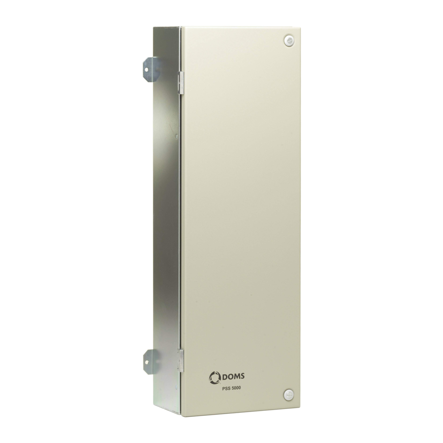
70 mm 170 mm Secure the PSS 5000 to the wall using the mounting lugs on the cabinet. The mounting lugs are located on the sides of the Standard cabinets. Use screws or bolts that are capable of supporting the weight of Note: the cabinet and its contents. -
Page 7: Power Up The Pss 5000
PSS 5000 – Installation Guide 2 Power Up the PSS 5000 Power Up the PSS 5000 To power up the PSS 5000 This procedure describes how to connect the power cable and LAN Ether- net connection to the PSS 5000. -
Page 8: Set The Ip Address
• Static – assigned manually via the service menus We recommend using a Static IP address as a dynamic IP address Note: may make it difficult to access the PSS 5000 remotely. The IP addresses for Port 41 and Port 42 must belong to separate Note: subnets. - Page 9 PSS 5000 – Installation Guide 2 Set the IP Address Methods of Setting the IP address of the LAN Port The IP address for Port 41 on the CPB539 can be set in one of two ways: • To assign an IP address to Port 41 (via a browser) •...
- Page 10 PSS 5000 – Installation Guide 2 Set the IP Address Locate Port 42 on the CPB and using a suitable Ethernet cable connect it to your Service PC. Ethernet Port 42 (IP address:192.168.1.2) Open a standard browser on your Service PC and in the URL field type in the IP address for Port 42: 192.168.1.2...
- Page 11 PSS 5000 – Installation Guide 2 Set the IP Address Do one of the following: • ) To assign a static IP address, go to step 7. Recommended • To assign a dynamic IP address, select and go to Enable DHCP Client step 8.
- Page 12 PSS 5000 – Installation Guide 2 Set the IP Address To assign an IP address to Port 41 (via Local Service Panel) This procedure describes how to use the Local Service Panel (LSP) on the CPB539 to set an IP address for Port 41. This is used to connect the to the LAN.
- Page 13 Set the IP address so that Port 41 and Port 42 belong to separate Note: subnets. The PSS 5000 can be connected to the LAN and you are ready to proceed to the next step in the process. See Also •...
-
Page 14: List The Protocol To Port Assignments
PSS 5000 – Installation Guide 2 List the Protocol to Port Assignments List the Protocol to Port Assignments To view the current protocol to port assignments This procedure describes how to use the FCC Web Application to view which protocols are assigned to the individual serial ports on the CPB. -
Page 15: Cable The Forecourt Devices
PSS 5000 – Installation Guide 2 Cable the Forecourt Devices Select 5. Setup 5.3. Protocol to Port Assignment A list of all the ports and the corresponding protocol to port assignments appears. Keep this page open and use the protocol to port assignment informa- tion to assist you in connecting the forecourt devices to the correct Hardware Interface Modules (HIMs). - Page 16 PSS 5000 – Installation Guide 2 Cable the Forecourt Devices Prepare the communication cables by removing the insulation as illus- trated below. Refer to the web service page and insert Protocol to Port Assignment each communication cable through the rubber grommet opposite the relevant HIM.
-
Page 17: Validate Device Connectivity
You are now ready to validate that all the forecourt devices are connected correctly and communicating with the PSS 5000. Validate Device Connectivity To validate connectivity between the PSS 5000 and the forecourt devices This procedure describes how to validate that the forecourt devices are communicating correctly with the PSS 5000. - Page 18 PSS 5000 – Installation Guide 2 Validate Device Connectivity Select 7. Diagnostics 7.1. Online List page appears. Online List Make sure that each forecourt device is listed in the col- Device Address umn. If this is not the case, repeat the steps in this section: •...
-
Page 19: Maintenance
To replace the fuse This procedure describes how to remove defective Mains fuses from the PSS 5000 Forecourt Controller and replace them with new ones. Turn off the power by removing the plug from the power inlet socket. Locate the fuse drawer, which is located at the power inlet socket. -
Page 20: Changing Hardware Interface Modules (Hims)
Changing Hardware Interface Modules (HIMs) To remove a HIM This procedure describes how to remove a HIM from the PSS 5000 cabinet. Turn off the power by removing the plug from the power inlet socket. Open the front cover by releasing the securing screws (and the lock if present). - Page 21 3 Changing Hardware Interface Modules (HIMs) To insert a HIM This procedure describes how to insert a HIM into the PSS 5000 cabinet. Turn off the power by removing the plug from the power inlet socket. Open the front cover by releasing the securing screws (and the lock if present).
-
Page 22: Technical Data
PSS 5000 – Installation Guide Technical Data General information Only equipment approved by Doms ApS is permitted to be installed in the PSS 5000 Forecourt Controller. The cables connecting the Hardware Interface Modules (HIMs) to the fore- court devices should be twisted pair with a plaited shield and with a mini- mum 80% cover. - Page 23 Forecourt devices (electronics for dispensers, terminals, tank gauges, etc.) The Mains cable must be installed according to the local regulations. The Mains power to the PSS 5000 is switched off by removing the Mains cable. 230 V version Mains power voltage (max.) 230 VAC +10% = 253 VAC Mains power voltage (min.)
- Page 24 PSS 5000 – Installation Guide Approvals data The approvals for the PSS 5000 are: Approvals • UL 60950-1, file E256596 • CB, IEC 60950-1 • Customs union TRCU, RU C-DK.AB72.B.01103 • MID Parts Certificate, SC0257-15 System States The LED states provided in the table below indicate the status of the sys- tem.
- Page 25 PSS 5000 – Installation Guide PSS Suite States The LED states provided in the table below indicate the status of the PSS Suite software. PSS LED Status PSS Application is not running PSS Suite error state Flashing PSS Suite operational (0.5 Hz)
-
Page 26: Revision Information
PSS 5000 – Installation Guide 5 Revision Information Revision Information Revision History This documentation has changed as follows: Rev. Date Description of Changes Jun. 13, 2016 First release. Nov. 04, 2016 Updated illustrations containing a CPB539. Dec. 15, 2016 Updated default IP address for Port 41.
Need help?
Do you have a question about the PSS 5000 and is the answer not in the manual?
Questions and answers