
Related Manuals for YOKOGAWA AQ7260 OTDR


Summary of Contents for YOKOGAWA AQ7260 OTDR
- Page 1 User’s Manual AQ7260 OTDR IM 813920300-01E 2nd Edition Y okogawa Electric Corporation...
- Page 2 This user's manual refers to AQ7260 OTDR which software version is 2.00 or later. Before using the AQ7260 (hereafter referred to as the instrument), please read this manual thoroughly.
- Page 3 • A certificate of compliance to guarantee the designed quality accompanies YOKOGAWA products. Prior to shipment, every YOKOGAWA product undergoes strict inspections that are carried out according to its quality assurance system. However, should breakdown occur arising from defects in manufacturing or accidents during transport, please contact the agent from whom the product was purchased.
- Page 4 CONVENTIONS USED IN THIS MANUAL Conventions Used in this Manual Safety Graphic Marks The following graphic marks are given in this manual to ensure the safe use of this instrument and to prevent injury and property damage. Before operating the instrument, please read the following carefully to gain thorough understanding.
- Page 5 CONVENTIONS USED IN THIS MANUAL Other Graphic Marks Caution This is called a caution mark. It indicates an operation or procedure that requires special care or a point to be observed regarding handling of the instrument. This is called a TIP mark. It indicates information that is useful for operation of the instrument.
- Page 6 SAFETY PRECAUTIONS Safety Precautions This section must be read to ensure safe use of the instrument. After reading, keep this manual in a safe place so that it can be referred to anytime it is required. For Safe Use of Laser Products This instrument uses a laser light source and as such, falls into the category of “class 1M laser product”...
- Page 7 SAFETY PRECAUTIONS WARNING Invisible laser beam is output from the emitter section. The emitter section is located on the top panel. A message “LASER ON” is displayed while a laser beam is emitted. Class 1M laser invisible radiation when LASER ON. Viewing the laser output with certain optical instruments (for example, eye loupes, magnifiers and microscopes) within a distance of 100mm may pose eye hazard.
- Page 8 SAFETY PRECAUTIONS Notes on Power Supply The instrument can be powered by the following two methods. • AC adapter (supplied with the instrument) • Battery pack (Model name : 3UR18650F-2) Refer For details on use of power supply, refer to page 3-3. Before connecting the instrument to the power, read the safety precautions given below.
-
Page 9: Battery Pack
SAFETY PRECAUTIONS Battery Pack WARNING If the battery fluid leaks from the battery pack and enters the eyes, immediately wash with clean water, such as tap water, (never rub the eyes) and consult a doctor. Failure to do so may cause damage to the eyes. The instrument and battery pack must be kept out of the reach of children. - Page 10 SAFETY PRECAUTIONS CAUTION Do not disassemble or modify the battery pack. The battery pack has built-in safety and protective functions designed to prevent danger. If these functions are damaged, the battery fluid may leak from the battery pack, resulting in heat generation, smoke, explosion or fire.
- Page 11 SAFETY PRECAUTIONS CAUTION The battery pack must only be used for this instrument. If charging is not complete even if the specified charging time has elapsed, stop charging. Continuing to charge the battery pack may result in battery fluid leakage, heat generation, smoke, explosion or fire.
- Page 12 Failure to observe this may result in fire, electric shock or breakdown. Restrictions Regarding Operating Conditions WARNING The power cord specified by YOKOGAWA must be used. Use of any other power cord may result in fire, electric shock or accident.
- Page 13 SAFETY PRECAUTIONS Notes on Installation For Personnel Performing Installation WARNING Do not connect the instrument to an AC outlet using an extension power cord. Doing so may result in heat generation or fire. CAUTION Do not dissemble or modify the instrument. Doing so may result in electric shock, fire or accident.
- Page 14 SAFETY PRECAUTIONS Restricted and Prohibited Items Regarding Operating Environment and Conditions WARNING Do not insert metal bars or such like into gaps on the instrument. Doing so may result in fire, electric shock or accident. CAUTION Keep the power cord away from heaters etc. Failure to observe this may result in electric shock.
- Page 15 SAFETY PRECAUTIONS Prohibited Items Regarding Installation Method WARNING Do not place heavy objects on the power cord, heat or pull it, and do not modify the power cord. Doing so may damage the cord, resulting in fire or electric shock. CAUTION Before transferring the instrument to another site, make sure that the power plug is removed from the AC outlet and all the external connecting cables are disconnected.
- Page 16 SAFETY PRECAUTIONS CAUTION When closing panels and covers, take care not to trap your fingers. If you are not going to use the instrument for a long period of time, the power plug must be removed from the AC outlet for safety reasons. It must also be removed in the event of thunderstorms.
- Page 17 SAFETY PRECAUTIONS Actions to be Taken in Case of Abnormalities WARNING Do not repair the instrument even though the instrument becomes faulty. Doing so may result in electric shock or injury. In addition, the instrument repaired by the user without permission will be exempt from the warranty. Should the instrument be dropped or damaged, turn OFF the power switch on the instrument, disconnect the power plug from the AC outlet and then contact your agent from whom the instrument was purchased.
-
Page 18: Other Precautions
SAFETY PRECAUTIONS Other Precautions Notes on Backup Battery CAUTION The instrument uses a lithium battery for memory backup. The instrument may malfunction suddenly due to battery life, therefore, early replacement of the battery is recommended. The life of the battery is approximately five years. Refer For details on replacement of the backup battery, refer to page 1-25. - Page 19 CONTENTS Structure of this Manual Chapter 1 BEFORE USING THE INSTRUMENT Explains the names and functions of each part of the instrument, and how to carry out daily maintenance. Chapter 2 BEFORE STARTING MEASUREMENT Explains how to set up the instrument. Chapter 3 PERFORMING MEASUREMENTS Explains how to set measurement conditions and how to measure optical fiber cables.
- Page 20 CONTENTS Contents Preface..................... I Warranty ....................II Conventions Used in this Manual ............III Safety Graphic Marks ......................III Other Graphic Marks ......................IV Safety Precautions ................V For Safe Use of Laser Products ..................... V Notes on Power Supply ......................VII Notes on Operating Environment and Conditions..............
- Page 21 CONTENTS Daily Maintenance ..................1-8 Cleaning the Exterior of the Instrument ................1-8 Cleaning the Optical Connector ...................1-9 Cleaning the Optical Adapter....................1-11 Replacing the Optical Module ..............1-12 Removing the Optical Module ....................1-12 Attaching a New Optical Module ..................1-14 Replacing the Optical Adapter ............... 1-16 Removing the Optical Adapter....................1-16 Attaching a New Optical Adapter..................1-17 Replacing the Battery Pack ..............
- Page 22 CONTENTS Warming Up the Instrument [Step 2] ............3-6 Connecting an Optical Fiber to the Instrument [Step 3] ......3-7 Cleaning the Optical Connector and Adapter............... 3-7 Connecting the Optical Fiber ....................3-8 Setting the Measurement Conditions/Auto Search Conditions [Step 4] .......................3-9 Displaying the Measurement Condition Change Window ..........
- Page 23 CONTENTS Inserting an Event ........................5-3 Deleting an Event .........................5-6 Moving an Event ........................5-9 Editing an Event Marker ................. 5-12 Editing the Event List................5-15 Displaying the List Edit Window ..................5-16 Editing the Event List......................5-18 Attaching a Comment to an Event ............5-23 Changing the Conditions and Performing Auto Search Again....
- Page 24 Return Value Format......................8-59 Command Input Examples (RS-232C) ................8-61 Chapter 9 SPECIFICATIONS ............9-1 Specifications of main frame ..............9-2 Specifications of optical modules ............9-4 Specifications of optional units..............9-7 Outside view drawings ................9-8 AQ7260 OTDR ........................9-9 AQ7261 SMF MODULE..................... 9-10 XXIII...
- Page 25 CONTENTS AQ7264 SMF MODULE ..................... 9-11 AQ7265 SMF MODULE .....................9-12 PRINTER/FDD UNIT......................9-13 PRINTER UNIT ........................9-14 Chapter 10 APPENDIX ..............10-1 10.1 Software Upgrade..................10-2 10.2 Troubleshooting ..................10-5 When the Instrument Appears Faulty .................10-5 When the Problem Cannot Be Solved................10-7 10.3 Glossary....................
- Page 26 CONTENTS Secondary reflection ......................10-15 Spatial resolution ......................10-15 Splice loss........................10-15 Two Point Approximate (TPA)..................10-15...
-
Page 28: Chapter 1 Before Using The Instrument
Chapter 1 BEFORE USING THE INSTRUMENT What is the AQ7260? ....................1-2 Installation, Storage and Transport................1-3 Power Supply ......................1-7 Daily Maintenance....................1-8 Replacing the Optical Module................. 1-12 Replacing the Optical Adapter ................1-16 Replacing the Battery Pack ..................1-19 Charging the Battery Pack.................. -
Page 29: What Is The Aq7260?
Chapter 1 BEFORE USING THE INSTRUMENT 1.1 What is the AQ7260? This instrument emits a light pulse into an optical fiber and searches faults from the end of the fiber, then calculates transmission loss effectively by detecting back scattering rays caused by Rayleigh scattering inside the fiber, and rays reflecting at connection points and fault points. -
Page 30: Installation, Storage And Transport
Chapter 1 BEFORE USING THE INSTRUMENT 1.2 Installation, Storage and Transport This section explains points to be observed when installing, storing or transporting the instrument. Unpacking and Receiving Inspection Prior to shipment, the instrument has undergone strict mechanical and electrical inspection to ensure its correct operation. -
Page 31: Notes On Storage
Chapter 1 BEFORE USING THE INSTRUMENT Notes on Storage This section explains points to be observed when storing the instrument for a long period of time. Notes Before Storage Dust, fingerprints, dirt and stains etc. collected on the instrument must be wiped off with a piece of cloth. -
Page 32: Notes On Transport
Chapter 1 BEFORE USING THE INSTRUMENT Notes on Transport This section explains points to be observed when transporting the instrument. Repacking To repack the instrument, the packing materials used to deliver the instrument must be used. If they have been discarded or damaged, pack the instrument as explained below. Wrap the instrument with a thick vinyl sheet to prevent entry of dust. - Page 33 Chapter 1 BEFORE USING THE INSTRUMENT Transport During transport, make sure that vibration is avoided and the required storage conditions are satisfied. Refer For details on the storage conditions, refer to page 1-4. Caution When the battery pack is transport by using aircraft. Pleas each package contains 12 battery pack or less.
-
Page 34: Power Supply
Chapter 1 BEFORE USING THE INSTRUMENT 1.3 Power Supply The instrument can run on AC power (AC battery is supplied with the instrument) or battery pack. The AC adapter must be connected to an AC power outlet (100 to 240 V, 50/60Hz). Necessary measures must be taken to prevent the following. -
Page 35: Daily Maintenance
Chapter 1 BEFORE USING THE INSTRUMENT 1.4 Daily Maintenance The instrument can be used for many years if daily maintenance is carried out properly. Daily maintenance is also important to prevent trouble and breakdowns. This section explains how to clean the following items. •... -
Page 36: Cleaning The Optical Connector
Chapter 1 BEFORE USING THE INSTRUMENT Cleaning the Optical Connector The end of the optical connector must be kept clean at all times. Collection of dust or dirt on the end may damage the optical adapter of the instrument, hindering correct measurement. - Page 37 Chapter 1 BEFORE USING THE INSTRUMENT •To check the condition of the end of the optical connector, use of a surface check microscope (x200 to x400) is helpful. •Various cleaners designed for optical fiber cables are available, including “OPTICAL FIBER CONNECTOR CLEANER” manufactured by NTT-ME. Product Name Appropriate Connector Types CLETOP reel-type A...
-
Page 38: Cleaning The Optical Adapter
Chapter 1 BEFORE USING THE INSTRUMENT Cleaning the Optical Adapter This section explains how to clean the optical adapter. Make sure that the power to the instrument is turned OFF. WARNING Never clean the instrument if the power is ON. Laser beams are invisible to the naked eye, but if they enter the eyes, they may cause impaired eyesight. -
Page 39: Replacing The Optical Module
Chapter 1 BEFORE USING THE INSTRUMENT 1.5 Replacing the Optical Module This section explains how to replace the optical module with a new one. Removing the Optical Module Caution The optical module cannot be replaced if the expansion unit is connected. Refer For the method of removing the expansion unit, refer to page 8-5. - Page 40 Chapter 1 BEFORE USING THE INSTRUMENT Remove the optical module cover. Loosen the four screws shown below counter-clockwise. Lift the optical module cover straight to remove it. Remove the optical module. Loosen the three screws shown below counter-clockwise. Then, pull out the optical module as shown below to remove it.
-
Page 41: Attaching A New Optical Module
Chapter 1 BEFORE USING THE INSTRUMENT Attaching a New Optical Module This section explains how to attach a new optical module. It is assumed that the optical module and its cover have been removed. Make sure that the power to the instrument is turned OFF. WARNING Do not replace the optical module while the instrument is powered ON. - Page 42 Chapter 1 BEFORE USING THE INSTRUMENT Fix the optical module. Tighten the three screws shown below clockwise to secure the optical module. Caution Make sure that the screws are tightened firmly. Attach the optical module cover. Tighten the four screws shown below clockwise. Caution Make sure that the screws are tightened firmly.
-
Page 43: Replacing The Optical Adapter
Chapter 1 BEFORE USING THE INSTRUMENT 1.6 Replacing the Optical Adapter This section explains how to replace the optical adapter with a new one. Removing the Optical Adapter Refer Refer to the Cautions given on page 1-18. Make sure that the power to the instrument is turned OFF. WARNING Do not replace the optical adapter while the power to the instrument is ON. -
Page 44: Attaching A New Optical Adapter
Chapter 1 BEFORE USING THE INSTRUMENT Attaching a New Optical Adapter Refer Refer to the Cautions given on page 1-18. Make sure that the power to the instrument is turned OFF. WARNING Do not replace the optical adapter while the power to the instrument is ON. Should the laser emit and enter the eyes, they may be seriously damaged or loss of eyesight may result. - Page 45 Chapter 1 BEFORE USING THE INSTRUMENT CAUTION • Take care not to damage the end of the optical fiberl. If the end of the optical fiber is damaged, correct measurement may no longer be possible or the optical fiber to be measured may also be damaged. •...
-
Page 46: Replacing The Battery Pack
Chapter 1 BEFORE USING THE INSTRUMENT 1.7 Replacing the Battery Pack This section explains how to replace the battery pack with a new one. Removing the Battery Pack Make sure that the power to the instrument is turned OFF. WARNING Do not replace the battery pack while the power to the instrument is ON. - Page 47 Chapter 1 BEFORE USING THE INSTRUMENT Remove the battery pack bracket. Loosen the screw shown below counter-clockwise to remove the bracket. CAUTION When removing the bracket, make sure that the right side of the instrument is not facing the floor. Doing so may cause the battery pack to drop, resulting in damage.
-
Page 48: Attaching A New Battery Pack
Chapter 1 BEFORE USING THE INSTRUMENT Attaching a New Battery Pack This section explains how to attach a new battery pack. It is assumed that the battery pack bracket has been removed. Make sure that the power to the instrument is turned OFF. WARNING Do not replace the battery pack while the power to the instrument is ON. - Page 49 Chapter 1 BEFORE USING THE INSTRUMENT Attach the battery pack bracket. Tighten the screw shown below clockwise to secure the bracket. Caution Make sure that the screw is tightened firmly. Close the battery pack protecting rubber. CAUTION Make sure that the battery pack protecting rubber is closed firmly. Failure to observe this may result in breakdown.
-
Page 50: Charging The Battery Pack
Chapter 1 BEFORE USING THE INSTRUMENT 1.8 Charging the Battery Pack This section explains how to charge the battery pack. When there is insufficient power in the battery pack, charge it as explained below. Caution Charging of the battery pack must be performed at temperatures of 5°C to 35°C. Charging outside this temperature range may not only deteriorate the battery pack’s performance or shorten its life, but in the worst case may also prevent start of charging. - Page 51 Chapter 1 BEFORE USING THE INSTRUMENT Refer For the method of removing the battery pack, refer to page1-19. Make sure that the power to the instrument is turned OFF. Refer For the method of turning OFF the power, refer to page 3-107. With the battery pack installed in the instrument, connect the AC adapter to the instrument.
-
Page 52: Replacing The Backup Battery
Chapter 1 BEFORE USING THE INSTRUMENT 1.9 Replacing the Backup Battery This section explains how to replace the backup battery with a new one. The backup battery must be replaced with a new one periodically, since it may cause sudden malfunctions due to its battery life even though the instrument is working properly. The backup battery must be replaced approximately every five years. - Page 53 Chapter 1 BEFORE USING THE INSTRUMENT Remove the battery. 3-1. Slide the battery as shown below. 3-2. Pull up the battery Caution When removing the backup battery, take care not to short-circuit the instrument. Insert a new battery. Caution Make sure that the battery is inserted in the correct direction. The printing board side is minus.
- Page 54 Chapter 1 BEFORE USING THE INSTRUMENT Attach the optical module and then attach its cover. Refer For the method of attaching the optical module and its cover, refer to page 1-12. CAUTION The instrument uses a lithium battery for memory backup. So, disposal of the instrument must be carried out according to the laws and regulations of the country and local authorities.
-
Page 55: Names Of Instrument Parts
Chapter 1 BEFORE USING THE INSTRUMENT 1.10 Names of Instrument Parts This section explains the name and function of each part of the instrument (front, rear, top and right side panels). It also explains standard accessories and options. Front View Caution The instrument uses a color LCD (hereafter called LCD). - Page 56 Chapter 1 BEFORE USING THE INSTRUMENT Name Description 8.4-inch color TFT (640 x 480 dots). Measured trace, measurement conditions and measured values are displayed. MODE key Used to switch the operation mode. Rotary knob Used to move the distance cursor or increase/decrease entered values. Holding down the key will allow you to move the distance cursor at different speeds.
-
Page 57: Rear View
Chapter 1 BEFORE USING THE INSTRUMENT Rear View Name Description Optical adapter Used to connect the optical fiber to be measured. Optical adapter cover Used to protect the optical adapter when the fiber to be measured is not connected. Sub module cover Used to protect the sub module port when no sub module is connected. - Page 58 Chapter 1 BEFORE USING THE INSTRUMENT WARNING When no optical fiber is connected, make sure that the optical adapter cover is closed. Laser beams are invisible to the naked eye, but if they enter the eyes, they may cause impaired eyesight. CAUTION When carrying the instrument, do not carry it by the stand.
-
Page 59: Top View
Chapter 1 BEFORE USING THE INSTRUMENT Top View Name Description Sub module port Used to connect an optional visible light source or optical power meter. Optical adapter Used to connect the optical fiber to be measured. DC power connector Used to connect the AC adapter. Power switch Used to turn ON/OFF the power to the instrument. -
Page 60: Right Side View
Chapter 1 BEFORE USING THE INSTRUMENT Right Side View Name Description Optical module cover Used to protect the optical module Battery pack section Used to accommodate a battery pack. 1-33... -
Page 61: Accessories
Chapter 1 BEFORE USING THE INSTRUMENT Accessories This section explains the accessories supplied with the instrument. Battery pack Shoulder belt User’s Manual 1-34... -
Page 62: Options
Chapter 1 BEFORE USING THE INSTRUMENT Options The section explains the options that can be purchased individually. AC adapter AC power cord Battery pack Optical module Universal adapter AQ9441 (*) Soft carrying case Expansion Unit Printer/FDD unit Printer unit 1-35... -
Page 63: Screen Display
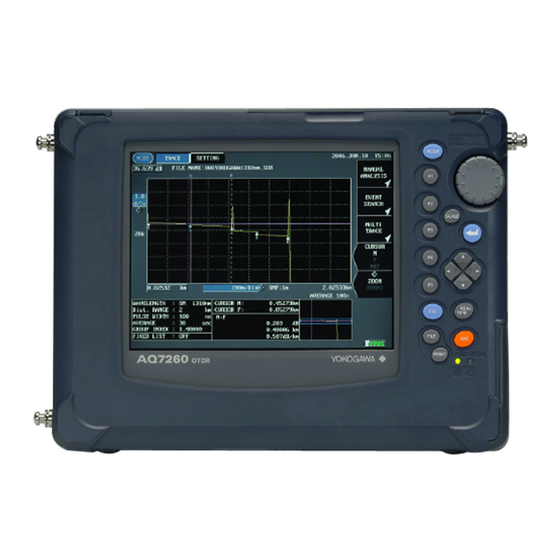
Chapter 1 BEFORE USING THE INSTRUMENT 1.11 Screen Display This section explains screen display. Description of Screen Display The main screen displays the measured trace and measurement conditions. The name and function of each part of the screen are explained below. 1-36... - Page 64 Chapter 1 BEFORE USING THE INSTRUMENT Name Description MODE Highlights the currently selected mode. Display start level Displays the vertical-axis display start level (above the trace display section). Vertical-axis scale Displays the value per grid along the vertical axis. Measurement conditions Displays various measurement conditions. Display start distance Displays the horizontal-axis display start distance (left to the trace display section).
- Page 65 Chapter 1 BEFORE USING THE INSTRUMENT Display of Measurement Conditions Name Description Displayed when the cursor link function is currently enabled. Displays the currently selected data size. 5k mode 20k: 20k mode 60k: 60k mode Displays the currently selected approximate method. LSA: Least squares approximate TPA: Two point approximate Displayed when the filter function is currently enabled.
- Page 66 Chapter 1 BEFORE USING THE INSTRUMENT Function Keys and Hierarchy Level Display When [MODE] is pressed, the function menu for currently selected mode will be displayed. The function keys are displayed in one of the three shapes, for each of which execution format has been set.
-
Page 67: Meaning Of Each Part Of The Trace
Chapter 1 BEFORE USING THE INSTRUMENT Meaning of Each Part of the Trace Near Reflection Splice loss Far end Near end Connection point between the instrument and optical fiber and its surrounding area Far end The end of an optical fiber cable and its surrounding area If the end of the optical fiber cable cannot be detected due to noise, “far end”... - Page 68 Chapter 1 BEFORE USING THE INSTRUMENT Splice Loss Splice loss occurs at areas where the optical fiber cable is fusion spliced. Spliced area Approximate straight line Splice loss Refer For details on approximate straight line, refer to pages 3-80 and 3-84. Reflection Reflection occurs at areas where the optical fiber cable is connected by a connector or areas where the optical fiber is cut off.
-
Page 69: Notes Before Performing Measurement
Caution • Special care must be taken not to allow communication failure. Should communication failure occur by mistake by the user, YOKOGAWA will not accept responsibility arising from that communication failure. • The AQ7260 main frame can use AQ7265 module at the software version 2.00 or later. -
Page 70: Chapter 2 Before Starting Measurement
Chapter 2 BEFORE STARTING MEASUREMENT Changing System Settings ..................2-2... -
Page 71: Changing System Settings
Chapter 2 CHANGING SYSTEM SETTINGS 2.1 Changing System Settings This chapter explains how to change the following system settings. • Changing the Display Language • Changing the Trace Type • Changing the Cursor Type • Changing the Grid Setting • Changing the Second Cursor Setting •... -
Page 72: Displaying The Setting Change Window
Chapter 2 CHANGING SYSTEM SETTINGS Displaying the Setting Change Window This section explains how to display the window by which system settings can be changed. Make sure there is no measurement currently in progress. Caution If measurement is in progress, it is not possible to change system parameter settings. -
Page 73: Changing Settings
Chapter 2 CHANGING SYSTEM SETTINGS Changing Settings This section explains how to change the setting for each parameter. The system settings are retained in the internal memory even if the instrument is turned OFF. So, when the instrument is turned ON, the system settings in effect just before the instrument was turned OFF last time will be restored. - Page 74 Chapter 2 CHANGING SYSTEM SETTINGS Locate the cursor to “日本語” by using the rotary knob or [ ] / [ ]. Press [ENTER] to register the change made to the language setting. Caution The change will not be registered if [ESC] is pressed instead of [ENTER].
- Page 75 Chapter 2 CHANGING SYSTEM SETTINGS Changing the Trace Type The trace type can be changed as explained below. ♦ Example: “LINE” → “DOT” Locate the cursor to “TRACE TYPE” by using the rotary knob or the arrow key. Press [ENTER]. A selection window will appear.
- Page 76 Chapter 2 CHANGING SYSTEM SETTINGS When “LINE” is selected When “DOT” is selected...
- Page 77 Chapter 2 CHANGING SYSTEM SETTINGS Changing the Cursor Type The cursor type can be changed as explained below. ♦ Example: “CROSS(+)” → “LINE( | )” Locate the cursor to “CURSOR” by using the rotary knob or the arrow key. Press [ENTER]. A selection window will appear.
- Page 78 Chapter 2 CHANGING SYSTEM SETTINGS When “CROSS(+)” is selected When “LINE( | )” is selected...
- Page 79 Chapter 2 CHANGING SYSTEM SETTINGS Changing the Grid Setting The grid setting can be changed as explained below. ♦ Example: “DISPLAY” → “NonDISPLAY” Locate the cursor to “GRID” by using the rotary knob or the arrow key. Press [ENTER]. A selection window will appear. NonDISPLAY Hides the grid.
- Page 80 Chapter 2 CHANGING SYSTEM SETTINGS When “DISPLAY” is select ed When “NonDISPLAY” is selected 2-11...
- Page 81 Chapter 2 CHANGING SYSTEM SETTINGS Changing the Second Cursor Setting Before explaining how to change the setting, an explanation is given below about the second cursor. The second cursor is used to check for the secondary reflection. The secondary reflection makes an event look as if it were present in places where it is actually not.
- Page 82 Chapter 2 CHANGING SYSTEM SETTINGS The second cursor can be changed as explained below. ♦ Example: “NonDISPLAY” → “DISPLAY” Locate the cursor to “SECOND CURSOR” by using the rotary knob or the arrow key. Press [ENTER]. A selection window will appear. *NonDISPLAY Hides the second cursor.
- Page 83 Chapter 2 CHANGING SYSTEM SETTINGS When “NonDISPLAY” is selected secondary reflection When “DISPLAY” is selected second cursor The second cursor is displayed at a position twice as far as the distance from the zero point as the cursor. 2-14...
- Page 84 Chapter 2 CHANGING SYSTEM SETTINGS Changing the Trace Form Setting Before explaining how to change the setting, an explanation is given below about trace form. This instrument can acquire data of maximum 60,000 points. However, since the number of dots on the LCD is limited, it is not possible to display all the acquired data at the same time.
- Page 85 Chapter 2 CHANGING SYSTEM SETTINGS MAXIMUM The data to be displayed on each dot is the maximum reflection level value among the data assigned to each dot. 1st dot: Display the maximum value among the 1st to 120th data. 2nd dot: Display the maximum value among the 121st to 240th data. 499th dot: Display the maximum value among the 59761st to 59880th data.
- Page 86 Chapter 2 CHANGING SYSTEM SETTINGS The trace form can be changed as explained below. ♦ Example: “DECIMATION” → “MAXIMUM” Locate the cursor to “TRACE FORM” by using the rotary knob or the arrow key. Press [ENTER]. A selection window will appear. *DECIMATION Selectable MEAN...
- Page 87 Chapter 2 CHANGING SYSTEM SETTINGS Changing the Distance Unit The distance unit can be changed as explained below. ♦ Example: “km” → “mile” Locate the cursor to “DIST. UNIT” by using the rotary knob or the arrow key. Press [ENTER]. A selection window will appear.
- Page 88 Chapter 2 CHANGING SYSTEM SETTINGS Changing the Distance Reference Mark Type The distance reference mark type can be changed as explained below. ♦ Example: “LINE” → “ARROW” Refer For the method of changing the distance reference, refer to page 7-27. Locate the cursor to “DIST.
- Page 89 Chapter 2 CHANGING SYSTEM SETTINGS When “LINE” is selected When “ARROW” is selected 2-20...
- Page 90 Chapter 2 CHANGING SYSTEM SETTINGS Changing the Number of dB Display Digits The number of dB display digits can be changed as explained below. ♦ Example: “∗∗.∗∗∗” → “∗∗.∗∗” Locate the cursor to “dB DIGIT” by using the rotary knob or the arrow key. Press [ENTER].
- Page 91 Chapter 2 CHANGING SYSTEM SETTINGS Changing the Display Color The display color can be changed as explained below. ♦ Example: “COLOR3” → “B&W” Locate the cursor to “DISPLAY” by using the rotary knob or the arrow key. Press [ENTER]. A selection window will appear. *COLOR1 Selectable COLOR2...
- Page 92 Chapter 2 CHANGING SYSTEM SETTINGS Changing the Date/Time Display Format The date/time display format can be changed as explained below. ♦ Example: “2004.APR.30 12:00” → “2004.4.30 12:00” Locate the cursor to “TYPE” by using the rotary knob or the arrow key. Press [ENTER].
- Page 93 Chapter 2 CHANGING SYSTEM SETTINGS Press [ENTER] to register the change made to the date/time display format. Caution The change will not be registered if [ESC] is pressed instead of [ENTER]. The selected display format will be reflected on the current time (displayed in the upper right corner of the screen), and date/time for the file list.
- Page 94 Chapter 2 CHANGING SYSTEM SETTINGS Changing the Date/Time The date/time can be changed as explained below. ♦ Example: “2004.JUN.15 9:06” → “2005.JUN.15 9:20” Locate the cursor to “INPUT” by using the rotary knob or the arrow key. Press [ENTER]. The following window will appear. 2-25...
- Page 95 Chapter 2 CHANGING SYSTEM SETTINGS Change the year. 3-1. Locate the cursor to “YEAR” by using the rotary knob or [ ] / [ ]. 3-2. Press [ENTER]. A selection window will appear. 3-3. Locate the cursor to “2005” by using the rotary knob or [ ] / [ ]. 3-4.
- Page 96 Chapter 2 CHANGING SYSTEM SETTINGS Changing the Lockout Setting The lockout function is to prevent the preset measurement conditions and system settings being changed by other operators. If this function is enabled, the measurement conditions and system settings cannot be changed. The lockout setting can be changed as explained below.
- Page 97 Chapter 2 CHANGING SYSTEM SETTINGS Press [ENTER]. The following window will appear. Enter a lockout code (4-digit code) as follows. In this example, “7260” is entered. 5-1 Locate the cursor to “7” by using the rotary knob or [ ] / [ ]. 5-2 Press [ENTER].
- Page 98 Chapter 2 CHANGING SYSTEM SETTINGS Enter the same lockout code again. Enter it according to steps 5-1 to 5-9. Caution The lockout function will be enabled when the same lockout code is entered at both steps 5 and 6. Do not forget the lockout code. It will be required when disabling the function. Disabling the Lockout Function Perform steps 1 and 2.
- Page 99 Chapter 2 CHANGING SYSTEM SETTINGS Changing the Alarm Sound Setting If this setting is enabled (ON), the buzzer will sound when a warning message is displayed. The alarm sound setting can be changed as explained below. ♦ Example: “ON” → “OFF” Locate the cursor to “ALARM SOUND”...
- Page 100 Chapter 2 CHANGING SYSTEM SETTINGS Changing the Power Save Setting The power save function is to save power consumption by turning OFF the LCD display’s backlight automatically when the instrument is ON but not operated for a certain period of time.
- Page 101 Chapter 2 CHANGING SYSTEM SETTINGS Locate the cursor to “3min” by using the rotary knob or [ ] / [ ]. Press [ENTER] to register the change made to the power save setting. Caution The change will not be registered if [ESC] is pressed instead of [ENTER]. The screen becomes darker when the power save function is ON.
- Page 102 Chapter 2 CHANGING SYSTEM SETTINGS Changing the LCD Brightness Ease of reading the LCD display varies considerably with its brightness. The LCD brightness can be changed as explained below. ♦ Example: “NORMAL” → “DARK” In general, each brightness mode has the following features. BRIGHT The screen is easy to see when the surroundings are dark.
- Page 103 Chapter 2 CHANGING SYSTEM SETTINGS Press [ENTER]. A selection window will appear. BRIGHT Selectable LCD *NORMAL brightness levels DARK *: Indicates the default setting. Locate the cursor to “DARK” by using the rotary knob or [ ] / [ ]. Press [ENTER] to register the change made to the LCD brightness.
- Page 104 Chapter 2 CHANGING SYSTEM SETTINGS Changing the Print Type The print type can be changed as explained below. ♦ Example: “HORIZONTAL” → “SCREEN” Locate the cursor to “PRINT TYPE” by using the rotary knob or the arrow key. Press [ENTER]. A selection window will appear.
- Page 105 Chapter 2 CHANGING SYSTEM SETTINGS When “HORIZONTAL” is selected When “VERTICAL” is selected When “SCREEN” is selected 2-36...
- Page 106 Chapter 2 CHANGING SYSTEM SETTINGS Changing the Print Color The print color can be changed as explained below. ♦ Example: “B&W” → “DISPLAY” Caution Selection of print color is not possible if an expansion unit has been set in the printer setting.
-
Page 107: Restoring The Default System Settings
Chapter 2 CHANGING SYSTEM SETTINGS Restoring the Default System Settings This section explains how to restore the default settings for all the system parameters. Display the setting change window. Refer For the method of displaying the setting change window, refer to page 2-3. Press [F1](INITIALIZE). -
Page 108: Performing Measurements
Chapter 3 PERFORMING MEASUREMENTS Flow of Measurement Steps ..................3-2 Turning ON the Power [Step 1]................. 3-3 Warming Up the Instrument [Step 2]................. 3-6 Connecting an Optical Fiber to the Instrument [Step 3] ......... 3-7 Setting the Measurement Conditions/Auto Search Conditions [Step 4]....3-9 Setting the File Name/Location to Store the File [Step 5] ........ -
Page 109: Flow Of Measurement Steps
Chapter 3 PERFORMING MEASUREMENTS 3.1 Flow of Measurement Steps This section explains the flow of optical fiber measurement. Step 1: Turning ON the Power Step 2: Warming Up the Instrument Step 3: Connecting an Optical Fiber to the Instrument Step 4: Setting the Measurement Conditions/Auto Search Conditions Step 5: Setting the File Name / Select drive and folder to Store... -
Page 110: Turning On The Power [Step 1]
Chapter 3 PERFORMING MEASUREMENTS 3.2 Turning ON the Power [Step 1] This section explains how to turn ON the power to the instrument. Caution If the instrument has been stored outside the operating temperature range, do not turn ON the power immediately. A temperature sensor is provided inside the instrument. -
Page 111: When Using Ac Power
Chapter 3 PERFORMING MEASUREMENTS When Using AC Power Caution •If you are going to use AC power to operate the instrument, the battery pack must be removed from the instrument. •Using AC adapter is only indoors (0 to 40 °C). Don’t use outdoors. Refer For the method of removing the battery pack, refer to page 1-19. -
Page 112: When Using The Battery Pack
Chapter 3 PERFORMING MEASUREMENTS When Using the Battery Pack Caution •To prevent trouble with the battery pack, check its appearance periodically for damage, such as cracks and deformation, and battery fluid leakage. •If the charged battery pack is stored for a long period of time, the operating time will be shortened due to natural discharge. -
Page 113: Warming Up The Instrument [Step 2]
Chapter 3 PERFORMING MEASUREMENTS 3.3 Warming Up the Instrument [Step 2] After the instrument is powered ON (Step 1), warm up the instrument for 30 minutes to stabilize it. Warm-up operation will enable acquisition of more accurate measurement data. -
Page 114: Connecting An Optical Fiber To The Instrument [Step 3]
Chapter 3 PERFORMING MEASUREMENTS 3.4 Connecting an Optical Fiber to the Instrument [Step 3] This section explains how to connect the optical fiber to be measured to the instrument. Cleaning the Optical Connector and Adapter Check the type of the optical adapter. Before cleaning the optical connector and adapter, make sure that the connector of the optical fiber to be measured has the same type as that of the optical adapter. -
Page 115: Connecting The Optical Fiber
Chapter 3 PERFORMING MEASUREMENTS Connecting the Optical Fiber This section explains how to connect an optical fiber by taking an example of connecting a FC connector. Open the optical connector cover on the top of the instrument. Fit the tab of the optical connector into the slot on the optical adapter, and insert the connector into the adapter. -
Page 116: Step 4]
Chapter 3 PERFORMING MEASUREMENTS 3.5 Setting the Measurement Conditions/Auto Search Conditions [Step 4] Before starting measurement of the optical fiber, it is necessary to set conditions under which the measurement is to be performed. This section explains how to change the following measurement conditions and auto search conditions. -
Page 117: Displaying The Measurement Condition Change Window
Chapter 3 PERFORMING MEASUREMENTS Displaying the Measurement Condition Change Window This section explains how to display the window by which the measurement conditions can be changed. Make sure there is no measurement currently in progress. Caution If measurement is in progress, some items cannot be changed. Press [MODE] to locate the cursor to “TRACE”. - Page 118 Chapter 3 PERFORMING MEASUREMENTS Press [F5](MEASURE CONDITION LIST). The following measurement condition change window will appear. 3-11...
-
Page 119: Changing The Measurement Conditions
Chapter 3 PERFORMING MEASUREMENTS Changing the Measurement Conditions Measurement conditions will be retained in the internal memory even if the instrument is turned OFF. So, when the instrument is turned ON, the measurement conditions in effect immediately before the instrument was turned OFF previously will be restored. - Page 120 Chapter 3 PERFORMING MEASUREMENTS Press [ENTER]. A selection window will appear. This instrument also allows setting multiple wavelengths and continuously measures an optical fiber cable with the set wavelengths. The wavelengths that can be set vary with the optical module used. Optical module Selectable wavelengths AQ7261...
- Page 121 Chapter 3 PERFORMING MEASUREMENTS Changing the Measurement Condition Auto Setting To simplify operation, the instrument provides a function that allows it to check the state of the optical fiber at the start of measurement and set the following measurement conditions automatically.
- Page 122 Chapter 3 PERFORMING MEASUREMENTS Locate the cursor to “AUTO RANGE” by using the rotary knob or [ ] / [ ]. Press [ENTER] to register the change made to the measurement condition auto setting. Press [F4] (DONE) to register the changes made to the measurement conditions.
- Page 123 Chapter 3 PERFORMING MEASUREMENTS Changing the Distance Range The distance range can be changed as explained below. ♦ Example: “40km” → “80km” •The distance range cannot be changed if “AUTO RANGE” has been selected for AUTO SET. •A distance range that is longer than the optical fiber to be measured must be set. Correct measurement will not be possible if a distance range shorter than the optical fiber is set.
- Page 124 Chapter 3 PERFORMING MEASUREMENTS Press [ENTER]. A selection window will appear. The distance ranges that can be selected vary with the optical module and wavelength used. The table below shows the distance ranges that can be selected in the case of AQ7264 optical module. Wavelength 1.31µm 1.55µm...
- Page 125 Chapter 3 PERFORMING MEASUREMENTS Changing the Pulse Width The pulse width can be changed as explained below. ♦ Example: “100ns” → “200ns” Caution The pulse width cannot be changed if “AUTO RANGE” has been selected for AUTO SET. The pulse width has the following features. •Short pulse width: Enables measurement with high spatial resolution, but not measurement at long distances.
- Page 126 Chapter 3 PERFORMING MEASUREMENTS Press [ENTER]. A selection window will appear. The pulse widths that can be selected vary with the optical module, wavelength and distance range selected. The table below shows the pulse widths that can be selected in the case of AQ7264 optical module and wavelength of 1.55µm. 80km 10km 160km...
- Page 127 Chapter 3 PERFORMING MEASUREMENTS Changing the Attenuation If excessive reflection occurs at the optical connector’s connection point or optical fiber‘s break point, the trace may be saturated. To prevent saturation of the trace, attenuation is used. The attenuation setting can be changed as explained below. ♦...
- Page 128 Chapter 3 PERFORMING MEASUREMENTS Press [ENTER]. A selection window will appear. •If the trace is saturated, measurement cannot be performed with high sensitivity. •The attenuations that can be selected vary with the optical module, wavelength and pulse width selected. The table below shows the attenuations that can be selected in the case of AQ7264 optical module and wavelength 1.55µm.
- Page 129 Chapter 3 PERFORMING MEASUREMENTS Changing the Average Condition Average condition means the method of averaging the data obtained by measurement. The following two average methods are available. • Averaging by times • Averaging by intervals The average condition can be changed as explained below. ♦...
- Page 130 Chapter 3 PERFORMING MEASUREMENTS Press [F4] (DONE) to register the changes made to the measurement conditions. When changing the condition for two or more items, it is recommended to change the condition for each item first and then press [F4]. Refer Refer to the notes given on changing the measurement conditions (page 3-50).
- Page 131 Chapter 3 PERFORMING MEASUREMENTS Changing the Average Time/Average Interval The average time can be changed as explained below. ♦ Example: “2^16” → “2^13” (*1) Locate the cursor to “AVE TIMES” by using the rotary knob or the arrow key. *1: “AVE TIME” is displayed if “TIMES 2^*” or “TIMES *k” is selected for “AVE CONDITION”, and “AVE INTERVAL”...
- Page 132 Chapter 3 PERFORMING MEASUREMENTS Locate the cursor to “2^13” by using the rotary knob or [ ] / [ ]. Press [ENTER] to register the change made to the average time. Press [F4] (DONE) to register the changes made to the measurement conditions.
- Page 133 Chapter 3 PERFORMING MEASUREMENTS Changing the Group Index The group index can be changed as explained below. ♦ Example: “1.48000” → “1.50000” Caution •Distance calculation is performed using the group index. So measured distance will not be accurate if the given group index is also not accurate. •The group index for each wavelength is stored in the memory.
- Page 134 Chapter 3 PERFORMING MEASUREMENTS Locate the cursor to “4” by using [ ] / [ ]. Change to “5” by using the rotary knob or [ ]. Locate the cursor to “8” by using [ ] / [ ]. Change to “0” by using the rotary knob or [ ]. Press [ENTER] to register the change made to the group index.
- Page 135 Chapter 3 PERFORMING MEASUREMENTS Changing the Data Size The data size can be changed as explained below. ♦ Example: “20k MODE” → “5k MODE” Locate the cursor to “DATA SIZE” by using the rotary knob or the arrow key. Press [ENTER]. A selection window will appear.
- Page 136 Chapter 3 PERFORMING MEASUREMENTS Locate the cursor to “5k MODE” by using the rotary knob or [ ] / [ ]. Press [ENTER] to register the change made to the data size. Press [F4] (DONE) to register the changes made to the measurement conditions.
- Page 137 Chapter 3 PERFORMING MEASUREMENTS Changing the Average Method Before explaining how to change the setting, an explanation is given below regarding average method. This instrument allows use of the following three average methods. • Hi-Speed • Normal • Hi-Return Hi-Speed This method is used to measure the entire area using the preset attenuation.
- Page 138 Chapter 3 PERFORMING MEASUREMENTS Normal This method is used to obtain a satisfactory trace when measuring a long optical fiber, by dividing the measurement area into blocks and setting an appropriate attenuation for each block. Division of the measurement area into blocks and setting of an appropriate attenuation for each block are carried out automatically by the instrument.
- Page 139 Chapter 3 PERFORMING MEASUREMENTS The average method can be changed as explained below. ♦ Example: “NORMAL” → “Hi-RETURN” Locate the cursor to “AVERAGE METHOD” by using the rotary knob or the arrow key. Press [ENTER]. A selection window will appear. Hi-RETURN Selectable *NORMAL...
-
Page 140: Changing The Measured Data Auto Saving Conditions
Chapter 3 PERFORMING MEASUREMENTS Changing the Measured Data Auto Saving Conditions Changing the Measured Data Auto Saving Setting Measured data auto saving is a function to save the acquired data in a specified storage media after average measurement was done. This section explains how to change the measured data auto saving setting. - Page 141 Chapter 3 PERFORMING MEASUREMENTS Locate the cursor to “ON” by using the rotary knob or [ ] / [ ]. Press [ENTER] to register the change made to the auto saving. Press [F4] (DONE) to register the changes made to the measurement conditions.
-
Page 142: Changing The Auto Search Conditions
Chapter 3 PERFORMING MEASUREMENTS Changing the Auto Search Conditions Changing the Event Search Setting Event search is a function to automatically search for events in the acquired data after average measurement was done. The event search setting can be changed as explained below. ♦... - Page 143 Chapter 3 PERFORMING MEASUREMENTS Press [F4] (DONE) to register the changes made to the measurement conditions. When changing the condition for two or more items, it is recommended to change the condition for each item first and then press [F4]. Refer Refer to the notes given on changing the measurement conditions (page 3-50).
- Page 144 Chapter 3 PERFORMING MEASUREMENTS Changing the Approximate Method Before explaining how to change the setting, an explanation is given below regarding approximate method. When calculating splice loss or return loss, a straight line is assumed for calculation. This straight line is called the approximate line. The following two methods are available to assume the approximate line.
- Page 145 Chapter 3 PERFORMING MEASUREMENTS An explanation of TPA is given below. TPA calculates the loss based on the level difference between the specified two points. There is a possibility that variation of calculated loss caused by operators is reduced and repeatability of calculated loss is changed considerably.
- Page 146 Chapter 3 PERFORMING MEASUREMENTS Press [ENTER]. A selection window will appear. Selectable *LSA approximate methods *: Indicates the default setting. Locate the cursor to “TPA” by using the rotary knob or [ ] / [ ]. Press [ENTER] to register the change made to the approximate method. Press [F4] (DONE) to register the changes made to the measurement conditions.
- Page 147 Chapter 3 PERFORMING MEASUREMENTS Changing the Back Scatter Level The light traveling through an optical fiber causes phenomena called Rayleigh scattering. Among these scattering rays, those which travel in the opposite direction of incident rays are called back scattering rays. The backscatter level set here will be used as a constant to calculate the return loss for each event and the total return loss.
- Page 148 Chapter 3 PERFORMING MEASUREMENTS Press [ENTER]. A selection window will appear. −10.00dB Selectable −64.99dB back scatter level (0.01dB step) Default setting Wavelength 1.31µm: −50.00dB Wavelength 1.55µm: −52.00dB Locate the cursor to “0” by using [ ] / [ ]. Change to “2” by using the rotary knob or [ ]. Locate the cursor to “1”...
- Page 149 Chapter 3 PERFORMING MEASUREMENTS Changing the Splice Loss Threshold When auto search is executed, splice losses exceeding the threshold set here will be detected as events. The splice loss threshold can be changed as explained below. ♦ Example: “0.28dB” → “0.35dB” Refer For details on splice loss, refer to page 1-41.
- Page 150 Chapter 3 PERFORMING MEASUREMENTS Locate the cursor to “8” by using [ ] / [ ]. Change to “5” by using the rotary knob or [ ]. Press [ENTER] to register the change made to the splice loss threshold. Press [F4] (DONE) to register the changes made to the measurement conditions.
- Page 151 Chapter 3 PERFORMING MEASUREMENTS Changing the Return Loss Threshold When auto search is executed, return losses exceeding the threshold set here will be detected as events. The return loss threshold can be changed as explained below. ♦ Example: “50dB” → “38dB” Refer For details on return loss, refer to page 1-41.
- Page 152 Chapter 3 PERFORMING MEASUREMENTS Change to “8” by using the rotary knob or [ ]. Press [ENTER] to register the change made to the return loss threshold. Press [F4] (DONE) to register the changes made to the measurement conditions. When changing the condition for two or more items, it is recommended to change the condition for each item first and then press [F4].
- Page 153 Chapter 3 PERFORMING MEASUREMENTS Changing the Fiber End Threshold When auto search is executed, events exceeding the threshold set here will be detected as the fiber end. The fiber end threshold can be changed as explained below. ♦ Example: “3dB” → “10dB” Refer For details on the fiber end, refer to page 1-40.
- Page 154 Chapter 3 PERFORMING MEASUREMENTS Press [ENTER] to register the change made to the fiber end threshold. Press [F4] (DONE) to register the changes made to the measurement conditions. When changing the condition for two or more items, it is recommended to change the condition for each item first and then press [F4].
- Page 155 Chapter 3 PERFORMING MEASUREMENTS Changing the Plug Check Setting The plug check function checks the connection condition between the instrument and optical fiber to be measured. When this function is enabled (ON), emission of laser from the instrument will be prevented if the optical fiber is not connected or it is connected but not properly.
- Page 156 Chapter 3 PERFORMING MEASUREMENTS Changing the Average Continue Setting Refer For average measurement continue and the method of changing the average continue setting, refer to page 3-62. 3-49...
-
Page 157: Notes On Changing Of Measurement Conditions / Auto Search Conditions
Chapter 3 PERFORMING MEASUREMENTS Notes on Changing of Measurement Conditions / Auto Search Conditions Caution If you try to close the measurement condition / auto search condition change (*1) window without pressing [F4] (DONE) , the following message will appear. *1: Press [MODE] or [ESC]. - Page 158 Chapter 3 PERFORMING MEASUREMENTS To restore the previous condition setting, press [F2] (UNDO). Undo can be performed up to five times. Assuming that the wavelength, distance range and pulse width are changed in this order as follows. :1.31µm → 1.55µm Wavelength Distance range:40km →...
-
Page 159: Restoring The Default Measurement Conditions / Auto Search Conditions
Chapter 3 PERFORMING MEASUREMENTS Restoring the Default Measurement Conditions / Auto Search Conditions This section explains how to restore the default measurement conditions / auto search conditions. Display the measurement condition setting window. Refer For the method of displaying the measurement condition setting window, refer to page 3-10. -
Page 160: Setting The File Name/Location To Store The File [Step 5]
Chapter 3 PERFORMING MEASUREMENTS 3.6 Setting the File Name/Location to Store the File [Step 5] If the measured data auto saving function of the measurement condition has been enabled, the acquired data is automatically saved when an average measurement is completed. -
Page 161: Measuring An Optical Fiber [Step 6]
Chapter 3 PERFORMING MEASUREMENTS 3.7 Measuring an Optical Fiber [Step 6] This section explains how to measure the optical fiber connected to the instrument and display the measured data. This instrument allows use of the following two measurement methods. • Real time measurement •... -
Page 162: Performing Real Time Measurement
Chapter 3 PERFORMING MEASUREMENTS Performing Real Time Measurement Real time measurement uses the default average time set to the instrument to perform measurement and display the measured data. The average time set by the user will be disabled. Since measurement conditions can be changed during real time measurement, changes in the trace occurring as a result of changes in the measurement conditions can be observed in real time. -
Page 163: Performing Average Measurement
Chapter 3 PERFORMING MEASUREMENTS Performing Average Measurement Average measurement obtains data for each pulse, calculates the mean of the data obtained for all the pulses, and then displays it. This method improves the signal to noise ratio (S/N), and is effective when you want to detect weak signals overwhelmed by noise. - Page 164 Chapter 3 PERFORMING MEASUREMENTS •A message “LASER ON” is displayed during measurement. •The following bar showing progress will appear during measurement. •Average measurement will end automatically, and “100%” will be displayed when it is completed successfully. •If [AVE] is pressed during measurement, measurement will stop and the progress of averaging performed so far will be displayed.
- Page 165 Chapter 3 PERFORMING MEASUREMENTS Refer •For the method of entering information, refer to Chapter 4. •For the method to enable the event search function, refer to page 3-35. •For the method to enable the automatic saving function, refer to page 3-33. •For the method to select a storage media, refer to page 3-91.
-
Page 166: When The Trace Contains A Lot Of Noise
Chapter 3 PERFORMING MEASUREMENTS When the Trace Contains a Lot of Noise If the trace obtained by average measurement contains so much noise that the trace cannot be observed clearly, remove noise as explained below. • Use the filter function to eliminate noise. •... - Page 167 Chapter 3 PERFORMING MEASUREMENTS Press [ENTER]. A selection window will appear. • The filter function can be used for measured traces or recalled traces. • The filter has the following features. The signal to noise ratio (S/N) is improved by processing the trace digitally. However, this makes edges of the trace round, and therefore difficult to identify Fresnel reflection occurring in adjacent areas.
- Page 168 Chapter 3 PERFORMING MEASUREMENTS When “OFF” is selected When “ON” is selected Caution The filter setting will be retained in the internal memory even if the instrument is turned OFF. So, when the instrument is turned ON, the measurement conditions in effect immediately before the instrument was turned OFF previously will be restored.
- Page 169 Chapter 3 PERFORMING MEASUREMENTS Using the Average Measurement Continue Function The average measurement continue function allows you to perform average measurement on the obtained trace additionally. For instance, if the data obtained by average measurement (2^16) contains a lot of noise, enabling this function and starting average measurement will continue to perform average measurement on that data up to 2^18 times.
- Page 170 Chapter 3 PERFORMING MEASUREMENTS Locate the cursor to “ON” by using the rotary knob or [ ] / [ ]. Press [ENTER] to register the change made to the average measurement continue setting. Press [F4] (DONE) to register the changes made to the measurement conditions.
-
Page 171: Checking The Measured Data [Step 7]
Chapter 3 PERFORMING MEASUREMENTS 3.8 Checking the Measured Data [Step 7] This section explains how to display and check the details of measured data. Basic Operations Moving the Cursor The cursor can be moved as explained below. Make sure the CURSOR Dist. field is displayed in the window. Turn the rotary knob. - Page 172 Chapter 3 PERFORMING MEASUREMENTS •The cursor can move between the measurement start and end points. However, at the measurement start point, the cursor will not move any more even if the rotary knob is rotated counter-clockwise. Similarly, it will not move even if the rotary knob is rotated clockwise at the measurement end point.
- Page 173 Chapter 3 PERFORMING MEASUREMENTS Enlarging/Reducing the Trace in Size The currently displayed trace can be enlarged or reduced in size as explained below. Locate the cursor to that part of the trace you want to enlarge or reduce by turning the rotary knob. Press [SCALE] to highlight the vertical-axis scale (dB/Div)/horizontal-axis scale (km/Div).
- Page 174 Chapter 3 PERFORMING MEASUREMENTS Shifting the Trace The currently displayed trace can be shifted as explained below. Press [SCALE] to highlight the display start level (dB)/display start distance (km). The following items will be highlighted alternately each time [SCALE] is pressed. Display start level (dB)/display start distance (km) Vertical-axis scale (dB/Div)/horizontal-axis scale (km/Div) Use the arrow keys to shift the trace.
-
Page 175: When "Auto" Is Selected For "Event Search"
Chapter 3 PERFORMING MEASUREMENTS When “AUTO” is Selected for “EVENT SEARCH” When average measurement is completed successfully with “AUTO” currently selected for “EVENT SEARCH”, events will be searched and displayed as shown below. In the example of the above window, both trace and event list are displayed. It is possible to display an event list only or a trace only. - Page 176 Chapter 3 PERFORMING MEASUREMENTS Name Description TOTAL RL TOTAL RL Displays the return loss occurring between S and E points. If R point has been set, the return loss occurring between R and E points will be displayed. TOTAL LOSS Displays the total loss occurring between S and E points.
- Page 177 Chapter 3 PERFORMING MEASUREMENTS Changing the Current Event The current event is the event you are currently referring to. The current event can be changed by turning the rotary knob. Event 1 will be set as the current event just after auto search is completed. But the R point will be set as current event, if distance reference will be set.
-
Page 178: When "Manual" Is Selected For "Event Search"
Chapter 3 PERFORMING MEASUREMENTS When “MANUAL” is Selected for “EVENT SEARCH” The following window will appear at the end of average measurement if “MANUAL” is currently selected for “EVENT SEARCH”. If [F3] is pressed in this window, auto search will be performed automatically and the window shown on page 3-68 will appear. - Page 179 Chapter 3 PERFORMING MEASUREMENTS Checking the Distance from the Origin This section explains how to check the distance from the distance origin. I wonder if I could find the distance from the origin. Turn the rotary knob. The distance from the origin to the cursor position will be displayed. Cursor Distance from the origin to the cursor •Normally, the distance origin means the connection point between the instrument...
- Page 180 Chapter 3 PERFORMING MEASUREMENTS Checking the Distance between Two Points This section explains how to check the distance between the desired two points. I wonder if I could find the distance between two points. How many kilometers? 3-73...
- Page 181 Chapter 3 PERFORMING MEASUREMENTS Press [MODE] to locate the cursor to “MARKER” (“MARKER” is highlighted). Turn the rotary knob and locate the cursor to the start point of the distance to be found. Refer For the method of moving the cursor, refer to page 3-64. Press [F1] ( Marker will appear at the cursor position.
- Page 182 Chapter 3 PERFORMING MEASUREMENTS Press [F2] ( “ ” will appear at the cursor position. The distance between the two points will be displayed. Distance from the origin to Distance between the two points Inter-marker information SPLICE LOSS : RETURN LOSS : [a] / [b] dB/km dB/km...
- Page 183 Chapter 3 PERFORMING MEASUREMENTS Caution The inter-marker values (dB and dB/km) vary considerably depending on the currently selected approximate method. To find more accurate distance, enlarge the trace and fine-adjust the markers. Refer •For details on approximate method, refer to page 3-37. •For the method of enlarging the trace, refer to page 3-66.
- Page 184 Chapter 3 PERFORMING MEASUREMENTS Checking the Splice Loss Splice loss can be checked using the following two methods. • 4-point method • 6-point method An explanation is given above for each method. Refer For details on splice loss, refer to page 1-41. I wonder if I could find the splice loss for events.
- Page 185 Chapter 3 PERFORMING MEASUREMENTS 4-Point Method The 4-point method allows you to check splice loss for the desired events using four markers. Press [MODE] to locate the cursor to “MARKER” (“MARKER” is highlighted). Locate the cursor near the desired event by turning the rotary knob. Refer For the method of moving the cursor, refer to page 3-64.
- Page 186 Chapter 3 PERFORMING MEASUREMENTS Locate the cursor on the desired event by turning the rotary knob. Caution Events ( ) indicate the following positions. Positive splice loss Negative splice loss Reflection Press [F2] ( “ ” will appear at the cursor position. Markers , Y2 and will be set when...
- Page 187 Chapter 3 PERFORMING MEASUREMENTS Caution •If markers , Y2, , Y1 and Y3 are already set before , markers , Y2 and will not be set automatically. •Make sure that is set at the exact position. The splice loss will vary considerably depending on the position of marker Markers move closer to...
- Page 188 Chapter 3 PERFORMING MEASUREMENTS Caution The inter-marker values (dB and dB/km) vary considerably depending on the currently selected approximate method. Refer •For details on approximate method, refer to page 3-37. •For the method of deleting markers and cursor, refer to page 3-76. •For the method of displaying the approximate line, refer to page 7-3.
- Page 189 Chapter 3 PERFORMING MEASUREMENTS 6-Point Method The 6-point method allows you to check splice loss for the desired events using six markers. The distance from the previous event can be found by performing this method. In this explanation, it is assumed that four markers ( , Y2) have already been set.
- Page 190 Chapter 3 PERFORMING MEASUREMENTS Set marker Y1. 2-1. Locate the cursor to the position where Y1 is to be set, by turning the rotary knob. Refer For the position for marker Y1, refer to page 3-84. 2-2. Press [F5] (NEXT PAGE). 2-3.
- Page 191 Chapter 3 PERFORMING MEASUREMENTS Inter-marker information SPLICE LOSS : RETURN LOSS : [b] / [c] dB/km [e] / [f] dB/km Approximate line for Y1-Y3 Approximate line for Y2- Caution The inter-marker values (dB and dB/km) vary considerably depending on the currently selected approximate method.
- Page 192 Chapter 3 PERFORMING MEASUREMENTS Checking the Return Loss This section explains how to check the return loss for the desired event. I wonder if I could know the return loss for events. 3-85...
- Page 193 Chapter 3 PERFORMING MEASUREMENTS Press [MODE] to locate the cursor to “MARKER” (“MARKER” is highlighted). Locate the cursor near the desired event by turning the rotary knob. Refer For the method of moving the cursor, refer to page 3-64. Enlarge the trace. Refer For the method of enlarging the trace, refer to page 3-66.
- Page 194 Chapter 3 PERFORMING MEASUREMENTS Locate the cursor at the peak of the event by turning the rotary knob. Press [F2] ( The return loss will be displayed. Distance from the origin to Return loss Caution “<” mark will appear in front of the return loss value if the trace is saturated. The level of reflection occurring when the trace is saturated will be actually larger than that displayed.
-
Page 195: Recording The Measured Data [Step 8]
Chapter 3 PERFORMING MEASUREMENTS 3.9 Recording the Measured Data [Step 8] This section explains how to save and print the measured data. Saving the Measured Data This section explains how to save the measured data, by taking an example of the following file name and location. - Page 196 Chapter 3 PERFORMING MEASUREMENTS Displaying the File Operation Window Press [FILE]. The following file operation window will appear. The file operation window can also be displayed by pressing [MODE] and locating the cursor at the desired file. 3-89...
- Page 197 Chapter 3 PERFORMING MEASUREMENTS Changing the File Operation Setting This instrument allows various file operations (saving, recalling, deleting, printing, copying). This section explains how to change the file operation . ♦ Example: “COPY” → “SAVE” Press [F1] (FILE OPERATION). A selection window will appear. *SAVE Saves the measured data.
- Page 198 Chapter 3 PERFORMING MEASUREMENTS Switching the Drive to Another This section explains how to switch the drive. ♦ Example: “INTERNAL MEMORY” → “PCMCIA” Caution If no drives are installed on the instrument or if they are installed but not connected, it is not possible to select them.
- Page 199 Chapter 3 PERFORMING MEASUREMENTS Switching the Folder to Another This section explains how to change the folder. Assuming that the selected drive has the following folder structure. Root 2003 2004 1-15 16-30 1-15 16-31 1-15 16-30 1-15 16-31 1-15 16-31 The method of changing from one folder to another is explained below.
- Page 200 Chapter 3 PERFORMING MEASUREMENTS Press [ENTER]. A selection window will appear. The folder (e.g. root folder) selected in the selection window shows all the sub folders. To display all the sub folders of a sub folder, locate the cursor to the sub folder, and press [ ] or [ ].
- Page 201 Chapter 3 PERFORMING MEASUREMENTS Changing the File Type (Extension) This section explains how to change the file type. ♦ Example: “.BMP(Image)” → “.SOR (Telcordia)” Locate the cursor to “FILE TYPE” by using [ ] / [ ]. Press [ENTER]. A selection window will appear. *.SOR (Telcordia) Saves the measured data in a format that conforms to Telcordia SR-4731.
- Page 202 Chapter 3 PERFORMING MEASUREMENTS Caution •To recall a file saved using AQ7931 emulation software (Ver.2.8 or later), make sure that the data is saved in .TRD or SOR (Bellcore) format. •The trace data of measured by 60k in data size or 640km in distance range cannot be saved in TRD format.
- Page 203 Chapter 3 PERFORMING MEASUREMENTS Changing the File Name Format This section explains how to change the name type of a file. ♦ Example: “No.+COM” → ”No.+COM+No.” Caution When file type is selected .TRD(AQ7260) or .SOR(Bellcore), File name type can not be changed. Locate the cursor to “NAME TYPE”...
- Page 204 Chapter 3 PERFORMING MEASUREMENTS Refer For details on No., refer to page 3-98. Locate the cursor to “No.+COM+WL” by using the rotary knob or [ ] / [ ]. When using multi wavelength measurement function, please selects file name included wavelength as file name type. Refer For continuous measurement with multiple wavelengths, refer to page 7-52.
- Page 205 Chapter 3 PERFORMING MEASUREMENTS Changing the ID No. The No. is used in combination with the SUB No. described in the next section. Refer For the description on the increment of No., refer to page 3-100. This section explains how to change the main No. attached to a file name. ♦...
- Page 206 Chapter 3 PERFORMING MEASUREMENTS Locate the cursor to “0” (one’s digit) by using [ ] / [ ]. Change to “3” by using the rotary knob or [ ]. Press [ENTER] to register the change made to the ID No. 3-99...
- Page 207 Chapter 3 PERFORMING MEASUREMENTS Changing the Sub No. This section explains how to change the Sub No. attached to a file name. ♦ Example: “NONE” → “a-c” Caution When file type is selected .TRD(AQ7260) or .SOR(Bellcore), SUB No. can not be changed.
- Page 208 Chapter 3 PERFORMING MEASUREMENTS Locate the cursor to “a-c” by using the rotary knob or [ ] / [ ]. Press [ENTER] to register the change made to the sub No. 3-101...
- Page 209 Chapter 3 PERFORMING MEASUREMENTS Changing the Save Color This section explains how to change the save color. ♦ Example: “DISPLAY” → “B&W” Caution The save color can be specified only if “.BMP(Image)” or “.TIF(Image)” is selected as the file type. Locate the cursor to “SAVE COLOR”...
- Page 210 Chapter 3 PERFORMING MEASUREMENTS Changing the File Name This section explains how to change the comment part of the file name. Caution •The file name can consist of up to 43 characters in total. Comment: 29 characters No.: 4 characters Wavelength: 6 characters Extension: 4 characters •The comment cannot be changed if “No.”...
-
Page 211: Printing The Measured Data
Chapter 3 PERFORMING MEASUREMENTS Printing the Measured Data The following three print functions are available. • Printing the currently displayed window • Printing the trace and event list • Printing the event list Caution Before starting to print, make sure that a printer is connected to the instrument and correct print settings are made. - Page 212 Chapter 3 PERFORMING MEASUREMENTS Printing the Trace and Event List This section explains how to print both the measured trace and information on the events detected by auto search. Caution The trace and event list can be printed only if auto search has been performed. Display a window showing the trace and event list.
- Page 213 Chapter 3 PERFORMING MEASUREMENTS Press [F1] (SCREEN). A selection window will appear. *TRACE + LIST Selectable screens LIST TRACE *: Indicates the default setting. Locate the cursor to “LIST” by using the rotary knob or [ ] / [ ]. Press [ENTER] to register the change made to the print object setting.
-
Page 214: Turning Off The Power [Step 9]
Chapter 3 PERFORMING MEASUREMENTS 3.10 Turning OFF the Power [Step 9] Turning OFF the Power This section explains how to turn OFF the power to the instrument. Make sure there is no measurement currently in progress. A message “LASER ON” is displayed during measurement. Refer For the display in the laser ON , refer to page 3-55. -
Page 215: Disconnecting The Optical Fiber
Chapter 3 PERFORMING MEASUREMENTS Disconnecting the Optical Fiber Disconnect the optical fiber that has been measured from the instrument. CAUTION When disconnecting the optical connector, position the connector perpendicular to the optical adapter and remove it gently. Shaking it sideways or removing by force may not only damage the optical adapter, but also damage the ferrule on the optical connector. -
Page 216: Entering Characters
Chapter 4 ENTERING CHARACTERS Entering Characters ....................4-2 Editing Characters....................4-7... -
Page 217: Entering Characters
Chapter 4 ENTERING CHARACTERS 4.1 Entering Characters With this instrument, a comment (label) on traces can be entered. In addition to the comment, detailed information, such as the names of the company and personal who measured the optical fiber, and the file name to be used to save the measured data can be entered. -
Page 218: Displaying The Label Input Window
Chapter 4 ENTERING CHARACTERS Displaying the Label Input Window Press [MODE] and locate the cursor to “TRACE”. Press [F2] (LABEL). A window allowing you to enter a label will appear. -
Page 219: Entering A Label
Chapter 4 ENTERING CHARACTERS Entering a Label This section explains how to enter the following characters. ♦ Example: AQ7260 OTDR Caution The label can consist of up to 36 characters. A label can be entered even when measurement is in progress. - Page 220 Chapter 4 ENTERING CHARACTERS Press [ENTER]. Locate the character cursor to “0” by using the arrow key. Press [ENTER]. Locate the character cursor to “space” by using the arrow key. A space is provided for each line. Press [ENTER]. Locate the character cursor to “O” by using the arrow key. Press [ENTER].
- Page 221 Chapter 4 ENTERING CHARACTERS Press [ENTER]. “AQ7260 OTDR” is displayed in the [LABEL] field at the end of step 22. Check whether “AQ7260 OTDR” is displayed in the [LABEL] field. Refer For the method of editing the entered characters, refer to page4-7.
-
Page 222: Editing Characters
Current label "AQ72560 OTDR" Extra character Label to be entered "AQ7260 OTDR" Display the label input window. Refer For the method of displaying the label input window, refer to page 4-3. Push the rotary knob to switch the input mode to “INSERT”. -
Page 223: Changing A Character
Current label "AQ7250 OTDR" Wrong character Label to be entered "AQ7260 OTDR" Display the label input window. Refer For the method of displaying the label input window, refer to page 4-3. Push the rotary knob to switch the input mode to “OVERWRITE”. -
Page 224: Adding A Character
Current label "AQ7260 ODR" "T" is missing. Label to be entered "AQ7260 OTDR" Caution If the allowed maximum number of characters has already been entered or will be exceeded by adding new characters, it will not be possible to add them. - Page 225 Chapter 4 ENTERING CHARACTERS Press [ENTER]. Caution • The character you want to add will be added next to the blinking cursor. • When adding the character, make sure that the input mode is set to “INSERT”. If “OVERWRITE” is selected, the character at the blinking cursor will be overwritten by the one you enter.
- Page 226 Chapter 5 EDITING AUTOMATIC SEARCH RESULTS Editing an Event ....................... 5-2 Editing an Event Marker ..................5-12 Editing the Event List....................5-15 Attaching a Comment to an Event................5-23 Changing the Conditions and Performing Auto Search Again ........ 5-25...
-
Page 227: Editing Automatic Search Results
Chapter 5 EDITING AUTOMATIC SEARCH RESULTS 5.1 Editing an Event When measurement of an optical fiber starts and auto search is performed, detection of events will be performed by the instrument. In some cases, the instrument cannot detect events since the back scatter level at reflection points is excessively low or it detects noise as an event. -
Page 228: Inserting An Event
Chapter 5 EDITING AUTOMATIC SEARCH RESULTS Inserting an Event This section explains how to insert an event. Measure the optical fiber and perform auto search. Refer •For the method of measuring an optical fiber, refer to page 3-56. •For the screen that shows auto search results at the end of measurement, refer to page 3-68. - Page 229 Chapter 5 EDITING AUTOMATIC SEARCH RESULTS Press [ENTER]. The following screen will appear. Information regarding An event is to be inserted here. the current event is displayed. Press [F2] (EVENT EDIT). Locate the cursor to the point where an event is to be inserted by turning the rotary knob.
- Page 230 Chapter 5 EDITING AUTOMATIC SEARCH RESULTS Press [F1] (EVENT INSERT). The event is inserted. Caution One trace can be set up to 100 events. •When an event is inserted between event Nos. 2 and 3, the inserted event will be set as event 3 and a new No.
-
Page 231: Deleting An Event
Chapter 5 EDITING AUTOMATIC SEARCH RESULTS Deleting an Event This section explains how to delete an event. ♦ Example: Deleting event 5 Caution This function is not possible if only S and E events exist. Measure the optical fiber and perform auto search. Refer •For the method of measuring an optical fiber, refer to page 3-56. - Page 232 Chapter 5 EDITING AUTOMATIC SEARCH RESULTS Press [ENTER]. The following screen will appear. An event is to be deleted here. Information regarding the current event is displayed Press [F2] (EVENT EDIT). Press [F4] (NEXT EVENT) or [F5] (PREVIOUS EVENT) to set event 5 as the current event.
- Page 233 Chapter 5 EDITING AUTOMATIC SEARCH RESULTS Press [F2] (EVENT DELETE). The event is deleted. •A new No. will be assigned to each event located after the deleted event. •If the S event is deleted, event 1 will be set as the S event, and a new event No. will be assigned to each subsequent event.
-
Page 234: Moving An Event
Chapter 5 EDITING AUTOMATIC SEARCH RESULTS Moving an Event This section explains how to move an event. ♦ Example: Moving event 3 Measure the optical fiber and perform auto search. Refer •For the method of measuring an optical fiber, refer to page 3-56. •For the screen that shows auto search results at the end of measurement, refer to page 3-68. - Page 235 Chapter 5 EDITING AUTOMATIC SEARCH RESULTS Press [ENTER]. The following screen will appear. An event is to be moved here. Information regarding the current event is displayed. Press [F2] (EVENT EDIT). Press [F4] (NEXT EVENT) or [F5] (PREVIOUS EVENT) to set event No.3 as the current event.
- Page 236 Chapter 5 EDITING AUTOMATIC SEARCH RESULTS Locate the cursor to the point to which the current event is to be moved by turning the rotary knob. If necessary, enlarge the trace. Refer For the method of moving the cursor, refer to page 3-64. Press [F2] ( The event moves.
-
Page 237: Editing An Event Marker
Chapter 5 EDITING AUTOMATIC SEARCH RESULTS 5.2 Editing an Event Marker When auto search is performed, events will be searched by the instrument. An event marker ( , Y2, ) is added to each detected event to calculate splice loss etc. The splice loss and dB/km vary slightly depending on the event marker positions. - Page 238 Chapter 5 EDITING AUTOMATIC SEARCH RESULTS Press [ENTER]. Press [F2] (EVENT EDIT). Press [F4] (NEXT EVENT) or [F5] (PREVIOUS EVENT) to set event No.3 as the current event. Press [F3]. Locate the cursor to the point to which marker is to be moved by turning the rotary knob.
- Page 239 Chapter 5 EDITING AUTOMATIC SEARCH RESULTS Press [F1] ( The marker moves. •When a marker is moved, the information regarding events will be searched re-calculated. •The other marker positions can also be changed in the same way. 5-14...
-
Page 240: Editing The Event List
Chapter 5 EDITING AUTOMATIC SEARCH RESULTS 5.3 Editing the Event List Distance calculation is performed using the group index set in the measurement conditions. However, if two or more optical fibers are connected as a result of installation of new transmission system, the group index varies with the optical fibers. In this case, distance calculation can be performed with higher accuracy by setting the group index of each optical fiber. -
Page 241: Displaying The List Edit Window
Chapter 5 EDITING AUTOMATIC SEARCH RESULTS Displaying the List Edit Window This section explains how to display the window by which the event list can be changed. Measure the optical fiber and perform auto search. Refer •For the method of measuring an optical fiber and performing auto search, refer to page 3-56. - Page 242 Chapter 5 EDITING AUTOMATIC SEARCH RESULTS Press [F3] (LIST EDIT). The following window will appear. 5-17...
-
Page 243: Editing The Event List
Chapter 5 EDITING AUTOMATIC SEARCH RESULTS Editing the Event List Editing an Interval Distance With this instrument, the distance is calculated using the group index. However, in some cases, the distance between two points on the optical fiber is already known. In this case, the interval group index can be calculated by changing the distance. - Page 244 Chapter 5 EDITING AUTOMATIC SEARCH RESULTS Editing a Return Loss With this instrument, the return loss is normally calculated based on the back scatter level. However, in some cases, the return loss is already known. In this case, enter the return loss to calculate the back scatter level.
- Page 245 Chapter 5 EDITING AUTOMATIC SEARCH RESULTS Change the value by using the rotary knob or the arrow key. Press [ENTER], and the value is fixed. When the return loss is changed, the back scatter level will be re-calculated. The return loss for all the events is then re-calculated based on the newly calculated back scatter level.
- Page 246 Chapter 5 EDITING AUTOMATIC SEARCH RESULTS Editing an Section Group Index If two or more optical fibers are connected as a result of installation of new transmission system, the group index varies with the optical fibers. In this case, calculation of interval distance can be performed with higher accuracy by setting the group index of each optical fiber.
- Page 247 Chapter 5 EDITING AUTOMATIC SEARCH RESULTS Change the value by using the rotary knob or the arrow key. Press [ENTER], and the value is fixed. •When the interval group index is changed, the distance for the changed event will be re-calculated. •It is also possible not to display the interval group index.
-
Page 248: Attaching A Comment To An Event
Chapter 5 EDITING AUTOMATIC SEARCH RESULTS 5.4 Attaching a Comment to an Event This instrument allows you to attach a comment (event note) to each event detected by auto search. This method of attaching a comment to an event is explained below. ♦... - Page 249 Chapter 5 EDITING AUTOMATIC SEARCH RESULTS Press [ENTER]. A new screen will appear. Refer For the new screen, refer to page 3-106. Locate the cursor to “No.1 Event” by using the rotary knob or [ ] / [ ]. Press [F4] (EVENT NOTE EDIT). The comment input window will appear, so enter the desired comment.
-
Page 250: Changing The Conditions And Performing Auto Search Again
Chapter 5 EDITING AUTOMATIC SEARCH RESULTS 5.5 Changing the Conditions and Performing Auto Search Again It is possible to change search conditions for the data obtained by auto search, and perform auto search with the new conditions. The method of changing the following search conditions is explained below. •... -
Page 251: Displaying The Auto Search Condition Change Window
Chapter 5 EDITING AUTOMATIC SEARCH RESULTS Displaying the Auto Search Condition Change Window This section explains how to display the window by which the auto search conditions can be changed. Measure the optical fiber and perform auto search. Refer •For the method of measuring an optical fiber and performing auto search, refer to page 3-56. - Page 252 Chapter 5 EDITING AUTOMATIC SEARCH RESULTS Press [F2] (SEARCH CONDITION CHANGE). The auto search condition change window will appear as shown below. 5-27...
-
Page 253: Changing The Auto Search Conditions
Chapter 5 EDITING AUTOMATIC SEARCH RESULTS Changing the Auto Search Conditions Changing the Group Index Refer For details on group index, refer to page 3-26. Locate the cursor to “GROUP INDEX” by using the rotary knob or the arrow key. Press [ENTER]. - Page 254 Chapter 5 EDITING AUTOMATIC SEARCH RESULTS Changing the Approximate Method Refer For details on approximate method, refer to page 3-37. Locate the cursor to “APPROX. METHOD” by using the rotary knob or the arrow key. Press [ENTER]. A selection window will appear. Change to the desired approximate method.
- Page 255 Chapter 5 EDITING AUTOMATIC SEARCH RESULTS Changing the Back Scatter Level Refer For details on back scatter level, refer to page 3-40. Locate the cursor to “BACKSCATTER” by using the rotary knob or the arrow key. Press [ENTER]. A selection window will appear. Change to the desired back scatter level.
- Page 256 Chapter 5 EDITING AUTOMATIC SEARCH RESULTS Changing the Splice Loss Threshold Refer For details on splice loss threshold, refer to page 3-42. Locate the cursor to “SPLICE LOSS” by using the rotary knob or the arrow key. Press [ENTER]. A selection window will appear. Change to the desired splice loss threshold.
- Page 257 Chapter 5 EDITING AUTOMATIC SEARCH RESULTS Changing the Return Loss Threshold Refer For details on return loss threshold, refer to page 3-44. Locate the cursor to “RETURN LOSS” by using the rotary knob or the arrow key. Press [ENTER]. A selection window will appear. Change to the desired return loss threshold.
- Page 258 Chapter 5 EDITING AUTOMATIC SEARCH RESULTS Changing the Fiber End Threshold Refer For details on fiber end threshold, refer to page 3-46. Locate the cursor to “END OF FIBER” by using the rotary knob or the arrow key. Press [ENTER]. A selection window will appear.
- Page 259 Chapter 5 EDITING AUTOMATIC SEARCH RESULTS Changing the Fault Event Show/Hide Setting The fault event show/hide setting can be changed as explained below. ♦ Example: “DISPLAY” → “NonDISPLAY” Refer For details on fault event, refer to page 3-68. Locate the cursor to “FAULT EVENT” by using the rotary knob or the arrow key. Press [ENTER].
- Page 260 Chapter 5 EDITING AUTOMATIC SEARCH RESULTS Press [F1] (Re-SEARCH START). When “DISPLAY” is selected When “NonDISPLAY” is selected When changing the condition for two or more items, it is recommended to change the condition for each item first and then press [F1]. Refer Refer to the notes given on changing the search conditions (page 5-38).
- Page 261 Chapter 5 EDITING AUTOMATIC SEARCH RESULTS Changing the Splice Loss Threshold for Fault Events Caution The splice loss threshold for fault events cannot be changed if “NonDISPLAY” is selected for “FAULT EVENT”. Locate the cursor to “SPLICE LOSS” for “AUTOSEARCH THRESHOLD VALUE” by using the rotary knob or the arrow key.
- Page 262 Chapter 5 EDITING AUTOMATIC SEARCH RESULTS Changing the Return Loss Threshold for Fault Events Caution The return loss threshold for fault events cannot be changed if “NonDISPLAY” is selected for “FAULT EVENT”. Locate the cursor to “RETURN LOSS” for “AUTOSEARCH THRESHOLD VALUE”...
-
Page 263: Notes On Changing Of Auto Search Conditions
Chapter 5 EDITING AUTOMATIC SEARCH RESULTS Notes on Changing of Auto Search Conditions Caution If the auto search conditions are changed using this window, they will be used as the measurement conditions and auto search conditions to obtain data next time. If you are not going to use the conditions set by this window to obtain new data, the measurement conditions and auto search conditions must be changed. -
Page 264: File Operation
Chapter 6 FILE OPERATION File Operation......................6-2 Using the Utility Functions ..................6-22... -
Page 265: File Operation
Chapter 6 FILE OPERATION 6.1 File Operation This section explains the following file operation functions. • Saving a file • Recalling a file • Deleting a file • Printing a file • Copying a file Saving a File Refer For the method of saving a file, refer to page 3-88. -
Page 266: Recalling A File
Chapter 6 FILE OPERATION Recalling a File This section explains how to recall a file. Displaying the File Operation Window Press [FILE] to display the file operation window. Refer For details on the file operation window, refer to page 3-89. Press [F1] (FILE OPERATION). - Page 267 Chapter 6 FILE OPERATION Press [ENTER] to change file operation. The following window will appear. Selecting a Drive Caution If no drives are installed on the instrument or if they are installed but not connected, it is not possible to select them. In this case, only files that are stored in the internal memory can be recalled.
- Page 268 Chapter 6 FILE OPERATION Selecting a Folder Select the desired folder. Refer For the method of selecting a folder, refer to page 3-92. Selecting a File Type (Extension) Select the file type of the file to be recalled. Refer For the method of selecting a file type, refer to page 3-94. .SOR Displays a list of files saved in the file type that conforms to Bellcore GR-196-CORE and Telcordia SR-4731.
- Page 269 Chapter 6 FILE OPERATION Selecting the File to be Recalled Locate the cursor to the file to be recalled by turning the rotary knob. Press [F2] (FILE SELECT) to select the file. The color of the selected file name will change. “*” also appears in front of the file name.
-
Page 270: Deleting A File
Chapter 6 FILE OPERATION Deleting a File This section explains how to delete a file. Displaying the File Operation Window Press [FILE] to display the file operation window. Refer For details on the file operation window, refer to page 3-89. Press [F1] (FILE OPERATION). - Page 271 Chapter 6 FILE OPERATION Press [ENTER] to change file operation. The following window will appear. Selecting a Drive Caution If no drives are installed on the instrument or if they are installed but not connected, it is not possible to select them. In this case, only files that are stored in the internal memory can be deleted.
- Page 272 Chapter 6 FILE OPERATION Selecting a Folder Select the desired folder. Refer For the method of selecting a folder, refer to page 3-92. Selecting a File Type (Extension) Select the file type of the file to be deleted. Refer For the method of selecting a file type, refer to page 3-94. .SOR Displays a list of files saved in the file type that conforms to Bellcore GR-196-CORE and Telcordia SR-4731.
- Page 273 Chapter 6 FILE OPERATION Selecting the File to be Deleted Locate the cursor to the file to be deleted by turning the rotary knob. Press [F2] (FILE SELECT) to select the file. •The color of the selected file name will change. “*” also appears in front of the file name.
- Page 274 Chapter 6 FILE OPERATION Deleting the Selected File(s) Press [F4] (EXECUTE). The following window will appear. Press [F5] (YES) to delete the selected file(s). If [F1] (NO) is pressed, the procedure will go back to the end of step 9. 6-11...
-
Page 275: Printing A File
Chapter 6 FILE OPERATION Printing a File This section explains how to print the data saved in a file. Caution Before starting to print, make sure that a printer is connected to the instrument and correct print settings are made. Refer For the method of connecting/selecting a printer, refer to pages 8-3, 8-6, 8-16, and 8-18. - Page 276 Chapter 6 FILE OPERATION Locate the cursor to “PRINT” by using the rotary knob or [ ] / [ ]. Press [ENTER] to change file operation. The following window will appear. Selecting a Drive Caution If no drives are installed on the instrument or if they are installed but not connected, it is not possible to select them.
- Page 277 Chapter 6 FILE OPERATION Selecting a Folder Select the desired folder. Refer For the method of selecting a folder, refer to page 3-92. Selecting a File Type (Extension) Select the file type of the file to be printed. Refer For the method of selecting a file type, refer to page 3-94. .SOR Displays a list of files saved in the file type that conforms to Bellcore GR-196-CORE and Telcordia SR-4731.
- Page 278 Chapter 6 FILE OPERATION Selecting a Print Type Select the desired print type. The print type can also be selected in the SETTING mode. Refer For details on print type, refer to page 2-35. Selecting a Print Color Select the desired print color. The print type can also be selected in the SETTING mode.
- Page 279 Chapter 6 FILE OPERATION Selecting a Print Object The print object can be changed as explained below. ♦ Example: “TRACE + LIST” → “TRACE” Caution The print object cannot be changed if “.LST” has been selected as the file type. Locate the cursor to “PRINT OBJECT”...
- Page 280 Chapter 6 FILE OPERATION Selecting the File to be Printed Locate the cursor to the file to be printed by turning the rotary knob. Press [F2] (FILE SELECT) to select the file. •The color of the selected file name will change. “*” also appears in front of the file name.
-
Page 281: Copying A File
Chapter 6 FILE OPERATION Copying a File This section explains how to copy a file to another folder. Displaying the File Operation Window Press [FILE] to display the file operation window. Refer For details on the file operation window, refer to page 3-89. Press [F1] (FILE OPERATION). - Page 282 Chapter 6 FILE OPERATION Press [ENTER] to change file operation. The following window will appear. Selecting the Copy Source/Destination (Drive) Caution If no drives are installed on the instrument or if they are installed but not connected, it is not possible to select them. In this case, files can be copied within the internal memory.
- Page 283 Chapter 6 FILE OPERATION Selecting the Copy Source/Destination (Folder) Select the desired folder. Refer For the method of selecting a folder, refer to page 3-92. Selecting a File Type (Extension) Select the file type of the file to be copied. Refer For the method of selecting a file type, refer to page 3-94.
- Page 284 Chapter 6 FILE OPERATION Selecting the File to be Copied Locate the cursor to the file to be copied by turning the rotary knob. Press [F2] (FILE SELECT) to select the file. •The color of the selected file name will change. “*” also appears in front of the beginning of the file name.
-
Page 285: Using The Utility Functions
Chapter 6 FILE OPERATION 6.2 Using the Utility Functions This chapter explains how to use the following utility functions. • Initializing a drive • Deleting a folder • Creating a folder • Copying a folder 6-22... -
Page 286: Initializing A Drive
Chapter 6 FILE OPERATION Initializing a Drive This section explains how to initialize the specified storage media. Caution • Storage media for more than 32G byte cannot be formatted. • The storage media which does not format by DOS can not be initialized. Press [FILE]. - Page 287 Chapter 6 FILE OPERATION Select the drive to be initialized. Refer For the method of selecting a drive, refer to page 3-91. Press [F4] (DRIVE INITIALIZE). The following window will appear. Press [F5] (YES) to start initialization. Caution All the folders and files in the drive will be deleted. The drive will not be initialized if [F1] (NO) is pressed.
-
Page 288: Deleting A Folder
Chapter 6 FILE OPERATION Deleting a Folder This section explains how to delete the desired folder. Press [FILE]. Refer For details on the file operation window, refer to page 3-89. Press [F5] (UTILITY). Select the drive that contains the folder to be deleted. Refer For the method of selecting a drive, refer to page 3-91. - Page 289 Chapter 6 FILE OPERATION Press [F2] (FOLDER DELETE). The following window will appear. Press [F5] (YES) to start deletion. Caution If the specified folder contains files or sub folders, it cannot be deleted. In this case, a message will appear, so take necessary steps according the message. The folder will not be deleted if [F1] (NO) is pressed.
-
Page 290: Creating A Folder
Chapter 6 FILE OPERATION Creating a Folder This section explains how to create a folder. Press [FILE]. Refer For details on the file operation window, refer to page 3-89. Press [F5] (UTILITY). Press [F1] (FOLDER MAKE). The following window will appear. 6-27... - Page 291 Chapter 6 FILE OPERATION Select the drive in which you want to create a folder. Refer For the method of selecting a drive, refer to page 3-91. Select the desired folder. A new folder will be created as a sub folder of the selected folder. Refer For the method of specifying a folder, refer to page 3-92.
- Page 292 Chapter 6 FILE OPERATION Enter the desired folder name. Caution The folder name can consist of up to 16 characters. Refer For the method of entering a folder name, refer to Chapter 4. Press [F5] (DONE). The folder name is fixed. Press [F5] (EXECUTE).
-
Page 293: Copying A Folder
Chapter 6 FILE OPERATION Copying a Folder This section explains how to copy a folder. Press [FILE]. Refer For details on the file operation window, refer to page 3-89. Press [F5] (UTILITY). Press [F3] (FOLDER COPY). The following window will appear. 6-30... - Page 294 Chapter 6 FILE OPERATION Select the drive that contains the folder to be copied. Refer For the method of selecting a drive, refer to page 3-91. Select the folder to be copied. Refer For the method of specifying a folder, refer to page 3-92. Select the drive to which the folder is to be copied.
-
Page 296: Using Useful Functions
Chapter 7 USING USEFUL FUNCTIONS Initializing the Vertical-/Horizontal-Axis Scales ............7-2 Displaying Approximate Lines .................. 7-3 Using the Cursor Link Function ................7-7 Using the Label Fixed Form Input Function.............7-11 Using the Label Auto Increment Function............... 7-13 Entering Various Information for the Measured Trace ..........7-16 Changing the Distance Reference................ -
Page 297: Initializing The Vertical-/Horizontal-Axis Scales
Chapter 7 USING USEFUL FUNCTIONS 7.1 Initializing the Vertical-/Horizontal-Axis Scales This section explains how to restore the original scale of the trace that has been enlarged, reduced or shifted. I wonder if the vertical-/horizontal-axis scales could be initialized easily. Press [MODE] to locate the cursor to “MARKER”. Press [F5] (NEXT PAGE). -
Page 298: Displaying Approximate Lines
Chapter 7 USING USEFUL FUNCTIONS 7.2 Displaying Approximate Lines This section explains how to change the approximate line display setting. ♦ Example: “NonDISPLAY” → “DISPLAY” Refer For details on approximate method and approximate line, refer to page 3-37. I wonder if approximate lines could be displayed. -
Page 299: For Traces That Have Been Auto Searched
Chapter 7 USING USEFUL FUNCTIONS For Traces that Have Been Auto Searched Refer For the window that shows auto search results at the end of measurement, refer to page 3-68. Press [F1](SCREEN). A selection window will appear. *TRACE + LIST Selectable LIST screens... - Page 300 Chapter 7 USING USEFUL FUNCTIONS Press [F4] (APPROX. LINE). A selection window will appear. Selectable *NonDISPLAY approximate line setting DISPLAY *: Indicates the default setting. Locate the cursor to “DISPLAY” by using the rotary knob or [ ] / [ ]. Press [ENTER].
-
Page 301: For Traces That Have Not Been Auto Searched
Chapter 7 USING USEFUL FUNCTIONS For Traces that Have Not Been Auto Searched Refer For the window that is displayed just after measurement is finished (without auto search), refer to page 3-71. Press [MODE] to locate the cursor to “MARKER”. Press [F5] (NEXT PAGE). -
Page 302: Using The Cursor Link Function
Chapter 7 USING USEFUL FUNCTIONS 7.3 Using the Cursor Link Function The cursor link function keeps a certain distance among markers ( , Y1 to Y3). For instance, when the cursor is moved 1km, all the markers will be moved 1km in the same direction as the cursor. -
Page 303: For Traces That Have Been Auto Searched
Chapter 7 USING USEFUL FUNCTIONS For Traces that Have Been Auto Searched Refer For the window that shows auto search results at the end of measurement, refer to page 3-68. Press [F1](SCREEN). A selection window will appear. *TRACE + LIST Selectable LIST screens... - Page 304 Chapter 7 USING USEFUL FUNCTIONS Press [F5] (CURSOR LINK). A selection window will appear. *OFF Selectable cursor link *: Indicates the default setting. Locate the cursor to “ON” by using the rotary knob or [ ] / [ ]. Press [ENTER]. The cursor link function will be enabled and “LNK”...
-
Page 305: For Traces That Have Not Been Auto Searched
Chapter 7 USING USEFUL FUNCTIONS For Traces that Have Not Been Auto Searched Refer For the window that is displayed just after measurement is finished (without auto search), refer to page 3-71. Press [MODE] to locate the cursor to “MARKER”. Press [F5] (NEXT PAGE). -
Page 306: Using The Label Fixed Form Input Function
Chapter 7 USING USEFUL FUNCTIONS 7.4 Using the Label Fixed Form Input Function When labels are added to traces, they will be stored in the internal memory automatically. The label fixed form input function allows you to import a label from the memory (edit it if necessary) and add it to the current trace. - Page 307 Chapter 7 USING USEFUL FUNCTIONS Press [F1] (SELECT). A character input window will appear, with the selected label displayed in the label field. If necessary, edit the label. Refer For the method of editing a label, refer to page 4-7. Press [F5] (DONE) to confirm the label.
-
Page 308: Using The Label Auto Increment Function
Chapter 7 USING USEFUL FUNCTIONS 7.5 Using the Label Auto Increment Function The label auto increment function allows you to add a number at the end of the label and increase the number by one automatically. This function is useful when measuring a multi-fiber cable. - Page 309 Chapter 7 USING USEFUL FUNCTIONS Press [ENTER]. The following window will appear. Locate the cursor to “START No.” by using the rotary knob or [ ] / [ ]. “START No.” is already highlighted when this window appears. Press [ENTER]. A selection window will appear.
- Page 310 Chapter 7 USING USEFUL FUNCTIONS Press [ENTER]. A selection window will appear. *NONE Selectable sub No. *: Indicates the default setting. The label No. will increase as follows when “NONE” or “a-c” is selected. NONE: 001→002→003→004→ a-c: 001a→001b→001c→002a→002b→002c→ (When the start No. is set to “001”) Select “SUB No.”...
-
Page 311: Entering Various Information For The Measured Trace
Chapter 7 USING USEFUL FUNCTIONS 7.6 Entering Various Information for the Measured Trace In addition to a label, this instrument allows you to enter various pieces of information regarding the measured trace. The items that can be entered are shown below. •... -
Page 312: Displaying The Detailed Information Input Window
Chapter 7 USING USEFUL FUNCTIONS Displaying the Detailed Information Input Window Press [MODE] to locate the cursor to “TRACE”. Press [F2] (LABEL). A window allowing you to enter a label will appear. Press [F4] (DETAILED INFORMATION INPUT). A window allowing you to enter detailed information will appear. If [F1] (ALL DELETE) is pressed, all the currently entered characters will be deleted. -
Page 313: Entering Detailed Information
Chapter 7 USING USEFUL FUNCTIONS Entering Detailed Information Entering the Company Name Locate the cursor to “COMPANY NAME” by using the rotary knob or [ ] / [ ]. The cursor is already located at “COMPANY NAME” when the detailed information input window appears. - Page 314 Chapter 7 USING USEFUL FUNCTIONS Entering the Name Locate the cursor to “NAME” by using the rotary knob or [ ] / [ ]. Press [ENTER]. A character input window will appear. Caution The name can consist of up to 36 characters. Refer For the method of entering characters, refer to Chapter 4.
- Page 315 Chapter 7 USING USEFUL FUNCTIONS Entering the Cable ID Locate the cursor to “CABLE ID” by using the rotary knob or [ ] / [ ]. Press [ENTER]. A character input window will appear. Caution The cable ID can consist of up to 36 characters. Refer For the method of entering characters, refer to Chapter 4.
- Page 316 Chapter 7 USING USEFUL FUNCTIONS Entering the Fiber ID Locate the cursor to “FIBER ID” by using the rotary knob or [ ] / [ ]. Press [ENTER]. A character input window will appear. Caution The fiber ID can consist of up to 36 characters. Refer For the method of entering characters, refer to Chapter 4.
- Page 317 Chapter 7 USING USEFUL FUNCTIONS Entering the Fiber Type Locate the cursor to “FIBER TYPE” by using the rotary knob or [ ] / [ ]. Press [ENTER]. A selection window will appear. *SMF(652) Single mode fiber Selectable DSF(653) Dispersion-shifted fiber fiber types NZ-DSF (655) Non-zero dispersion shifted single mode fiber MMF(651) Multi mode fiber...
- Page 318 Chapter 7 USING USEFUL FUNCTIONS Entering the Cable Code Locate the cursor to “CABLE CODE” by using the rotary knob or [ ] / [ ]. Press [ENTER]. A character input window will appear. Caution The cable code can consist of up to 36 characters. Refer For the method of entering characters, refer to Chapter 4.
- Page 319 Chapter 7 USING USEFUL FUNCTIONS Entering the Originating Location Locate the cursor to “ORIGINATING LOCATION” by using the rotary knob or [ ] / [ ]. Press [ENTER]. A character input window will appear. Caution The originating location can consist of up to 36 characters. Refer For the method of entering characters, refer to Chapter 4.
- Page 320 Chapter 7 USING USEFUL FUNCTIONS Entering the Terminating Location Locate the cursor to “TERMINATING LOCATION” by using the rotary knob or [ ] / [ ]. Press [ENTER]. A character input window will appear. Caution The terminating location can consist of up to 36 characters. Refer For the method of entering characters, refer to Chapter 4.
- Page 321 Chapter 7 USING USEFUL FUNCTIONS Changing the Current Data Flag Locate the cursor to “CURRENT DATA FLAG” by using the rotary knob or [ ] / [ ]. Press [ENTER]. A selection window will appear. *BUILT (BC) Selectable REPAIRED (RC) current data flags OTHER (OT) *: Indicates the default setting.
-
Page 322: Changing The Distance Reference
Chapter 7 USING USEFUL FUNCTIONS 7.7 Changing the Distance Reference Normally, the instrument considers the distance reference to be the connection point between the instrument and the optical fiber to be measured, and calculates all the distance data, such as cursor position and marker positions, based on the distance reference. -
Page 323: For Traces That Have Been Auto Searched
Chapter 7 USING USEFUL FUNCTIONS For Traces that Have Been Auto Searched Refer For the window that shows auto search results at the end of measurement, refer to page 3-68. Press [F1](SCREEN). A selection window will appear. *TRACE + LIST Selectable LIST screens... - Page 324 Chapter 7 USING USEFUL FUNCTIONS Locate the cursor to the point to which the distance reference is to be set, by turning the rotary knob. To display the cursor at an accurate position, enlarge the trace. Refer For the method of enlarging the trace, refer to page 3-66. Press [F3] (DISTANCE REFERENCE SET).
- Page 325 Chapter 7 USING USEFUL FUNCTIONS •Carrying out step 7 with the distance reference set will restore the connection point between the instrument and optical fiber as the distance reference. •The mark shape of the distance reference can be changed. Refer For the method of changing the distance reference mark, refer to page 2-19.
-
Page 326: For Traces That Have Not Been Auto Searched
Chapter 7 USING USEFUL FUNCTIONS For Traces that Have Not Been Auto Searched Refer For the window that is displayed just after measurement is finished (without auto search), refer to page 3-71. Press [MODE] to locate the cursor to “MARKER”. Press [F5] (NEXT PAGE). - Page 327 Chapter 7 USING USEFUL FUNCTIONS Press [F2] (DISTANCE REFERENCE SET). The cursor position will be set as the distance reference. “REF” will be displayed at the left edge of the window. Caution •All the distance data will be re-calculated based on the new distance reference. •Carrying out step 4 with the distance reference set will restore the connection point between the instrument and optical fiber as the distance reference.
-
Page 328: Using The Event Fix Function
Chapter 7 USING USEFUL FUNCTIONS 7.8 Using the Event Fix Function When a master event is created and auto search is performed for the measured trace, this event fix function displays the information for the same distance as the master event. This function is useful for measurements like measurement of multi-fiber cables, in which the distances to the events occurring in each fiber are expected to be the same. - Page 329 Chapter 7 USING USEFUL FUNCTIONS Press [ENTER]. A new window will appear. Refer For details on the window, refer to page 3-106. Press [F3] (LIST EDIT). A new window will appear. Refer For details on the window, refer to page 5-17. Press [F2] (EVENT FIX).
- Page 330 Chapter 7 USING USEFUL FUNCTIONS Caution • The event fix function will be turned OFF (disabled) if measurement conditions (wavelength, distance range, pulse width, data size) are changed. It will also be turned OFF if the horizontal-axis scale is increased/decreased during real-time measurement.
-
Page 331: Using The Section Analysis Function
Chapter 7 USING USEFUL FUNCTIONS 7.9 Using the Section Analysis Function The section analysis function allows you to calculate total return loss and total loss within the specified section. This section explains how to specify a section. I wonder if I could get information for a certain section only. - Page 332 Chapter 7 USING USEFUL FUNCTIONS Press [ENTER]. A new window will appear. Refer For details on the window, refer to page 5-4. Press [F3] (SECTION ANALYSIS). Locate the cursor to the point from which section analysis is to be started, and then press [F1] (START POINT SET).
- Page 333 Chapter 7 USING USEFUL FUNCTIONS The total return loss is calculated based on the back scatter level at the near end. However, it can be re-calculated based on the back scatter level at the desired position (e.g. section analysis start point) instead of the near end. The method of changing the reference level is explained below.
-
Page 334: Manipulating Two Or More Traces
Chapter 7 USING USEFUL FUNCTIONS 7.10 Manipulating Two or More Traces This section explains the following functions. • Displaying multiple traces • Displaying the subtract trace of two traces • Merging two traces I wonder if I could compare the two traces. -
Page 335: Displaying Multiple Traces
Chapter 7 USING USEFUL FUNCTIONS Displaying Multiple Traces The following two methods are available to display multiple traces. • By recalling multiple files • By displaying a new trace while displaying the current trace • By making a measurement continuously on multiple wavelengths This section explains how to display a new trace while displaying the current trace. - Page 336 Chapter 7 USING USEFUL FUNCTIONS Refer • For the method of recalling multiple files, refer to page 6-3. • For the method to make a measurement continuously on multiple wavelengths, refer to page 7-52. Display a trace. Perform measurement or recall one file to display the window that is displayed before Auto search.
- Page 337 Chapter 7 USING USEFUL FUNCTIONS Change measurement conditions and start measurement. A new trace will be displayed. Caution The fixed trace will be discarded if the distance range is changed. 7-42...
-
Page 338: Displaying The Subtract Trace Of Two Traces
Chapter 7 USING USEFUL FUNCTIONS Displaying the Subtract Trace of Two Traces Displaying the Subtract Trace This section explains how to display the subtract trace of two traces (reference trace, target trace). Caution The subtract trace cannot be displayed unless the following measurement conditions are the same for both the reference and target traces. - Page 339 Chapter 7 USING USEFUL FUNCTIONS Analyzing the Subtract Trace This section explains how to set markers A and B on the subtract trace and calculate the loss occurring between those marker points. Locate the cursor to the position to which marker A is to be set. Press [F3] (MARKER A).
-
Page 340: Merging Two Traces
Chapter 7 USING USEFUL FUNCTIONS Merging Two Traces The 2-way trace function allows you to merge the events detected on an optical fiber in the direction from end A to end B with those detected in the direction from end B to end A. End A End B ×... - Page 341 Chapter 7 USING USEFUL FUNCTIONS Press [F5] (2WAY TRACE). The following window will appear. A list of merged events will be shown. •The merged trace of the two traces will not be displayed. But all of event maker displayed on the original direction trace. •The merged event list can be saved.
-
Page 342: Using The Light Source Function
Chapter 7 USING USEFUL FUNCTIONS 7.11 Using the Light Source Function The light source function allows use of the instrument as a light source, not as an OTDR. This section explains how to use the instrument as a light source. I wonder if I could use the instrument as a light source. -
Page 343: Displaying The Light Source Function Window
Chapter 7 USING USEFUL FUNCTIONS Displaying the Light Source Function Window Press [MODE] to locate the cursor to “OPTION”. The following window will appear. Caution “OPTION” cannot be selected if an optical module (AQ7261) is installed. 7-48... -
Page 344: Changing The Wavelength And Modulation Frequency
Chapter 7 USING USEFUL FUNCTIONS Changing the Wavelength and Modulation Frequency Changing the Wavelength The wavelength can be changed as explained below. ♦ Example: “1310nm” → “1550nm” Locate the cursor to “WAVELENGTH” by using the rotary knob or [ ] / [ ]. “WAVELENGTH”... - Page 345 Chapter 7 USING USEFUL FUNCTIONS Changing the Modulation Frequency The modulation frequency can be changed as explained below. ♦ Example: “CW” → “1kHz” Locate the cursor to “MODULATION” by using the rotary knob or [ ] / [ ]. Press [ENTER]. A selection window will appear.
-
Page 346: Emitting A Laser
Chapter 7 USING USEFUL FUNCTIONS Emitting a Laser Connect an optical fiber to the instrument. Press [F1] (LIGHT SOURCE). A selection window will appear. *OFF Selectable light source *: Indicates the default setting. Locate the cursor to “ON” by using the rotary knob or [ ] / [ ]. Press [ENTER]. -
Page 347: Making A Measurement Continuously Changing The Wavelengths
Chapter 7 USING USEFUL FUNCTIONS 7.12 Making a Measurement Continuously Changing the Wavelengths The characteristics of an optical fiber can be obtained more correctly by measuring the fiber using two or more wavelengths. This function increases the efficiency of measurement by saving the work to change the wavelength manually after a measurement was made on one wavelength. - Page 348 Chapter 7 USING USEFUL FUNCTIONS Press [F3] (MULTI WL MEASURE). A selection window will appear. *OFF Selectable light source *: Indicates the default setting. Locate the cursor to “ON” by using the rotary knob or [ ] / [ ]. Press [ENTER].
- Page 349 Chapter 7 USING USEFUL FUNCTIONS Locate the cursor to “SM 1.55µm” by using the rotary knob or arrow key. Press [ENTER] . " * " is displayed. • Check to make sure that "*" is added to the traces 1.31µm and 1.55µm. •...
- Page 350 Chapter 7 USING USEFUL FUNCTIONS • For the method to enable the event search function, refer to page 3-35. Refer • For the method to enable the auto saving function, refer to page 3-33. • If [AVE] is pressed during a continuous measurement, the following window will appear.
- Page 352 Chapter 8 USING OPTIONS AND EXTERNAL DEVICES Using Options......................8-2 Using External Devices .................... 8-9 Operating the Instrument from a Personal Computer..........8-22...
-
Page 353: Using Options And External Devices
Chapter 8 USING OPTIONS AND EXTERNAL DEVICES 8.1 Using Options This section explains how to connect and remove the following options to the instrument. • Printer/FDD unit • Printer unit... -
Page 354: Option Unit
Chapter 8 USING OPTIONS AND EXTERNAL DEVICES Option Unit Connecting This section explains procedure of mounted options to take printer/FDD unit for example. Make sure that the power to the instrument is turned OFF. WARNING Do not connect the printer/FDD unit while the power to the instrument is ON. Failure to observe this may result in an electric shock. - Page 355 Chapter 8 USING OPTIONS AND EXTERNAL DEVICES Place the projecting part on the unit between those on the instrument. Insert the unit’s connector into the expansion port. CAUTION When inserting the connector, hold the unit gently with the palms of your hands. Take care to hold the unit in such a way that pressure is not exerted on one point only or that it is held too strongly.
- Page 356 Chapter 8 USING OPTIONS AND EXTERNAL DEVICES Removing This section explains procedure of removed options to take printer/FDD unit for example. Make sure that the power to the instrument is turned OFF. WARNING Do not remove the printer/FDD unit while the power to the instrument is ON. Failure to observe this may result in an electric shock.
- Page 357 Chapter 8 USING OPTIONS AND EXTERNAL DEVICES Setting Up the Printer The instrument allows both optional printer unit and USB printer to be connected at the same time. In this case, the destination printer (the printer to which you want to print out) must be set up.
- Page 358 Chapter 8 USING OPTIONS AND EXTERNAL DEVICES Press [ENTER]. A selection window will appear. *EXTENSION UNIT Prints out to the optional printer unit. Selectable HP Prints out to the HP printer connected to a USB connector. printer makers EPSON Prints out to the EPSON printer connected to a USB connector.
- Page 359 Chapter 8 USING OPTIONS AND EXTERNAL DEVICES Setting the Recording Paper in the Printer The recording paper can be set in the printer as explained below. Press down the lever to remove the printer cover. Set the recording paper in the unit. Attach the printer cover.
-
Page 360: Using External Devices
Chapter 8 USING OPTIONS AND EXTERNAL DEVICES 8.2 Using External Devices This instrument allows use of the following external devices by connecting them to USB ports. • USB keyboard • PCMCIA memory card • USB printer • USB storage medium (FDD, memory) This section explains how to connect the above external devices to the instrument and remove them. -
Page 361: Usb Keyboard
Chapter 8 USING OPTIONS AND EXTERNAL DEVICES USB Keyboard Connecting A USB keyboard can be connected to the instrument as explained below. A USB keyboard can be connected even if the power to the instrument is currently Open the cover on the top of the instrument. Connect a USB keyboard to a USB connector (host side). - Page 362 Chapter 8 USING OPTIONS AND EXTERNAL DEVICES Using Using a keyboard makes entry of characters easy. This section explains points to be observed when using a USB keyboard. The keyboard can be used in character input windows only. Caution Basically, characters can be entered in the same way as you normally do with a personal computer.
- Page 363 Chapter 8 USING OPTIONS AND EXTERNAL DEVICES Removing The USB keyboard can be removed from the instrument as explained below. The USB keyboard can be removed even if the power to the instrument is currently Hold the keyboard cable’s connector and lift it straight to remove the keyboard. CAUTION When removing the keyboard, do not pull it by the cable.
-
Page 364: Pcmcia Memory Card
Chapter 8 USING OPTIONS AND EXTERNAL DEVICES PCMCIA Memory Card Connecting A PCMCIA memory card can be connected to the instrument as explained below. A PCMCIA memory card can be connected even if the power to the instrument is currently ON. Open the cover on the top of the instrument. - Page 365 Chapter 8 USING OPTIONS AND EXTERNAL DEVICES Removing The PCMCIA memory card can be removed from the instrument as explained below. The PCMCIA memory card can be removed even if the power to the instrument is currently ON. Press [MODE] to locate the cursor to “SETTING”. Press [F4] (PCMCIA REMOVE).
- Page 366 Chapter 8 USING OPTIONS AND EXTERNAL DEVICES Press the card eject button. The memory card will pop out. Lift the memory card straight to remove it. Caution Before removing the memory card, make sure that a message stating that the card can be removed safely is displayed.
-
Page 367: Usb Printer
Chapter 8 USING OPTIONS AND EXTERNAL DEVICES USB Printer Caution The following USB printers available to use this instrument at present. Hewlett Packard • Deskjet5160 • Deskjet5740 EPSON • PX-V500 • Stylus C45 Connecting A USB printer can be connected to the instrument as explained below. Caution The instrument allows two USB printers to be connected, but it cannot recognize them together. - Page 368 Chapter 8 USING OPTIONS AND EXTERNAL DEVICES Connect a USB printer to a USB connector (host side). Two USB connectors (host side) are available, and the printer can be connected to either of these. 8-17...
- Page 369 Chapter 8 USING OPTIONS AND EXTERNAL DEVICES Setting Up the Printer The instrument allows both optional printer unit and USB printer to be connected at the same time. In this case, the destination printer (the printer to which you want to print out) must be set up.
- Page 370 Chapter 8 USING OPTIONS AND EXTERNAL DEVICES Press [ENTER]. A selection window will appear. *EXTENSION UNIT Prints out to the optional printer unit. HP Prints out to the HP printer connected to a USB Selectable connector. printer makers EPSON Prints out to the EPSON printer connected to a USB connector.
- Page 371 Chapter 8 USING OPTIONS AND EXTERNAL DEVICES Removing The USB printer can be removed from the instrument as explained below. The USB printer can be removed even if the power to the instrument is currently Hold the printer cable’s connector and lift it straight to remove the printer. CAUTION When removing the printer, do not pull it by the cable.
-
Page 372: Usb Storage Medium
Chapter 8 USING OPTIONS AND EXTERNAL DEVICES USB Storage Medium Connecting A USB storage medium (FDD, memory) can be connected to the instrument as explained below. Caution The instrument allows two USB storage mediums to be connected, but it cannot recognize them together. -
Page 373: Operating The Instrument From A Personal Computer
Chapter 8 USING OPTIONS AND EXTERNAL DEVICES 8.3 Operating the Instrument from a Personal Computer By connecting the instrument to a personal computer, the instrument can be operated from the computer (by sending commands from the computer). This instrument controlled by following method. •... -
Page 374: Operation By Using Rs-232C
Chapter 8 USING OPTIONS AND EXTERNAL DEVICES Operation by using RS-232C Connecting the Instrument to a Personal Computer Caution The instrument can be connected to a personal computer using a RS-232C cross cable. Since the instrument has no RS-232C interface, a USB-to-Serial adapter must be provided by the user. - Page 375 Chapter 8 USING OPTIONS AND EXTERNAL DEVICES Open the cover on the top of the instrument. Connect the USB connector of the connecting cable to a USB connector (host side) on the instrument. Two USB connectors (host side) are available, and the personal computer can be connected to either of these.
- Page 376 Chapter 8 USING OPTIONS AND EXTERNAL DEVICES Setting the Instrument This section explains how to change the communication settings to allow the instrument to communicate with the personal computer. Turn ON the power to both the instrument and personal computer. Refer For the method of turning ON the power to the instrument, refer to page 3-3.
- Page 377 Chapter 8 USING OPTIONS AND EXTERNAL DEVICES Press [ENTER]. A selection window will appear. 2400 4800 *9600 Selectable 19200 baud rates 38400 57600 115200 *: Indicates the default setting. Locate the cursor to “38400” by using the rotary knob or [ ] / [ ]. Press [ENTER] to register the change made to the baud rate setting.
- Page 378 Chapter 8 USING OPTIONS AND EXTERNAL DEVICES Press [ENTER]. A selection window will appear. *NONE Disables flow control. Selectable flow HARDWARE Uses the flow control setting made on the device (personal control settings computer) connected to the instrument. *: Indicates the default setting. Locate the cursor to “HARDWARE”...
- Page 379 Chapter 8 USING OPTIONS AND EXTERNAL DEVICES Operating the Instrument The instrument can be operated by entering commands using the personal computer’s communication software. This section explains how to operate the instrument using HyperTerminal of Microsoft Windows2000. Start HyperTerminal. From the [Start] menu of Windows2000, select [Programs] - [Accessories] - [Communications] - [HyperTerminal] to start HyperTerminal.
-
Page 380: Operation By Using Gp-Ib
Chapter 8 USING OPTIONS AND EXTERNAL DEVICES Operation by using GP-IB Interface function This unit has the interface functions shown in Table of the GP-IB interface functions specified IEEE488.1. Code Interface function All send handshake function All receive handshake function Basic talker and serial pole functions Basic listener function All service request function... - Page 381 Chapter 8 USING OPTIONS AND EXTERNAL DEVICES Service Request function When the service request is valid, the service request signal is transmitted according to the table below. Explanation Always:0 Service request (0:None / 1: exist) Hardware information (0: normal / 1: abnormal) Always:0 Always:0 Plug check information (0: normal / 1: abnormal)
- Page 382 Chapter 8 USING OPTIONS AND EXTERNAL DEVICES Connecting the Instrument to a Personal Computer Caution The instrument can be connected to a personal computer using a GP-IB PC card (PCMCIA) and cable. Please use following GP-IB cards. Manufacturer: CONTEC CO., LTD. Model Name: GP-IB (CB) F Make sure that the power to both the instrument and computer is turned OFF.
- Page 383 Chapter 8 USING OPTIONS AND EXTERNAL DEVICES Setting the Instrument This section explains how to change the communication settings to allow the instrument to communicate with the personal computer. Turn ON the power to both the instrument and personal computer. Refer For the method of turning ON the power to the instrument, refer to page 3-3.
- Page 384 Chapter 8 USING OPTIONS AND EXTERNAL DEVICES Press [ENTER]. A selection window will appear. Selectable GP-IB address (1step) Default setting: 21 Locate the cursor to “7” by using the rotary knob or [ ] / [ ]. Press [ENTER] to register the change made to the GP-IB address setting. 8-33...
- Page 385 Chapter 8 USING OPTIONS AND EXTERNAL DEVICES Operating the Instrument This instrument can be controlled by entering commands using GP-IB control software of Start control software. Set the GP-IB address. Caution GP-IB address of setting is necessary to set same GP-IB address of instrument. Input commands.
-
Page 386: Control Commands
Chapter 8 USING OPTIONS AND EXTERNAL DEVICES Control Commands Device Message Function Description Numeric Header Part OTDR measurement Starts/stops OTDR measurement. start/stop m= 0: Stops measurement. 1: Starts real-time measurement. 2: Starts average measurement (continued). 3: Starts average measurement (new). Current average time No control command Cursor position... - Page 387 Chapter 8 USING OPTIONS AND EXTERNAL DEVICES Device Message Function Description Numeric Header Part Display start distance HPOS Sets the display start position for horizontal axis. m= SXXXX.XXXXX “S” indicates a sign. It can be omitted in the case of “+”.
- Page 388 Chapter 8 USING OPTIONS AND EXTERNAL DEVICES Device Message Function Description Numeric Header Part Company name CORP Enters the company name. Up to 36 characters can be entered. The device message must be separated from the company name using a comma “,”. Name Enters the name.
- Page 389 Chapter 8 USING OPTIONS AND EXTERNAL DEVICES Device Message Function Description Numeric Header Part Plug check Enables (ON)/disables (OFF) the optical plug connection check. m= 0: OFF 1: ON Measurement condition Sets the measurement condition automation / event automation / event detection function.
- Page 390 Chapter 8 USING OPTIONS AND EXTERNAL DEVICES Device Message Function Description Numeric Header Part 4-10 Average time /average Sets the time (interval) for average processing. interval setting m= −2: 2^10 3: 2^15 −1: 2^11 4: 2^16 0: 2^12 5: 2^17 1: 2^13 6: 2^18 2: 2^14...
- Page 391 Chapter 8 USING OPTIONS AND EXTERNAL DEVICES Device Message Function Description Numeric Header Part Sets the wavelength. 4-17 Wavelength setting (for MWAVE m,n,o,p m= 0 : The first wavelength of the unit is OFF multi wavelength 1 : The first wavelength og the unit is ON measurement) n= 0 : The second wavelength of the unit is OFF 1 : The second wavelength of the unit is ON...
- Page 392 Chapter 8 USING OPTIONS AND EXTERNAL DEVICES Device Message Function Description Numeric Header Part 5-14 Fiber end threshold Sets the fiber end threshold. (BPL) 3 ≤ m ≤ 10:1step 5-15 Fault event show/hide Shows/hides fault events. setting m= 0: Shows fault events. 1: Hides fault events.
- Page 393 Chapter 8 USING OPTIONS AND EXTERNAL DEVICES Device Message Function Description Numeric Header Part File list print m, n Prints a list of files. m: Set the drive. m= 0: FD (expansion unit) 1: Built-in memory 2: - 3: PCMCIA 4: - 5: USB n: Set the folder name.
- Page 394 Chapter 8 USING OPTIONS AND EXTERNAL DEVICES Device Message Function Description Numeric Header Part 10-2 Copy COPY m, n, o, p, Sets the copy source file. If “o” is not specified, copy will be made for each folder. m: Set the copy source drive. m= 0: FD (expansion unit) 1: Built-in memory 2: -...
- Page 395 Chapter 8 USING OPTIONS AND EXTERNAL DEVICES Device Message Function Description Numeric Header Part 11-1 Trace type Sets the trace display method. m= 0: Dot 1: Line 11-2 Cursor type Sets the cursor display method. Second cursor m= 0: “+” (Second cursor OFF) 1: “|”...
- Page 396 Chapter 8 USING OPTIONS AND EXTERNAL DEVICES Device Message Function Description Numeric Header Part 11-15 Alarm sound setting BEEP Enables/disables the alarm. m= 0: Disables the alarm. 1: Enables the alarm. 11-16 Power save setting Sets the power save function. m= 0: OFF 1: 30sec 2: 1min...
- Page 397 Chapter 8 USING OPTIONS AND EXTERNAL DEVICES Device Message Function Description Numeric Header Part 13-8 Sends file PC to OTDR FILESEND m,n,o,p m received drive. m= 0 : FD(EXTENSION UNIT) 1 : INTERNAL MEMORY 2 : − 3 : PCMCIA 4 : −...
-
Page 398: Request Commands
Chapter 8 USING OPTIONS AND EXTERNAL DEVICES Request Commands Device Message Function Description Numeric Header Part OTDR measurement Requests the measurement status. start/stop 0: Stops measurement. 1: Starts real-time measurement. 2: Starts average measurement (continued). 3: Starts average measurement (new). 4: Starts multi wavelength measurement Current average time TIMR... - Page 399 Chapter 8 USING OPTIONS AND EXTERNAL DEVICES Device Message Function Description Numeric Header Part Distance from the Requests the distance from the origin. origin SXXXX.XXXXXTT “S” indicates a sign. “TT” indicates the distance unit. 1-10 Display start level VPOSR Requests the display start level. SXX.XXX 1-11 Trace information...
- Page 400 Chapter 8 USING OPTIONS AND EXTERNAL DEVICES Device Message Function Description Numeric Header Part 3-10 Data flag LCDFR Requests the data flag. 0: - 1: BC (as-Built Condition) 2: RC (as-Repaired Condition) 3: OT (Other) 3-11 Auto increment Requests the LABEL auto increment status. 0: ON 1: OFF 3-12...
- Page 401 Chapter 8 USING OPTIONS AND EXTERNAL DEVICES Device Message Function Description Numeric Header Part Attenuation Requests the attenuation. 0: 0.00 dB 11: 13.75 dB 1: 1.25 dB 12: 15.00 dB 2: 2.50 dB 13: 16.25 dB 3: 3.75 dB 14: 17.50 dB 4: 5.00 dB 15: 18.75 dB 5: 6.25 dB...
- Page 402 Chapter 8 USING OPTIONS AND EXTERNAL DEVICES Device Message Function Description Numeric Header Part Requires wavelength setting. 4-17 Multi wavelength MWAVER Return value formant : m,n,o,p measurement setting m= 0 : The first wavelength of the unit is OFF 1 : The first wavelength og the unit is ON n= 0 : The second wavelength of the unit is OFF 1 : The second wavelength of the unit is ON o= 0 : The third wavelength of the unit is OFF...
- Page 403 Chapter 8 USING OPTIONS AND EXTERNAL DEVICES Device Message Function Description Numeric Header Part 5-18 Auto search event SPPR Requests the number of events detected by auto count output search. (R point is included, END point is not included) 5-19 Auto search result SPDR Requests the auto search results.
- Page 404 Chapter 8 USING OPTIONS AND EXTERNAL DEVICES Device Message Function Description Numeric Header Part Recorded file name m, n, o Request the names of recorded files. Return value format: XXXXXXX,XXXXXXX, m: Specify the drive. m= 0: FD (expansion unit) 1: Built-in memory 2: - 3: PCMCIA 4: -...
- Page 405 Chapter 8 USING OPTIONS AND EXTERNAL DEVICES Device Message Function Description Numeric Header Part 11-4 Trace display DOTR Requests the trace display dot method. 0: Decimation 1: Mean 2: Maximum 3: Envelope 11-5 Distance unit Requests the distance unit. 0: km 1: mile 2: kf 11-6...
- Page 406 Chapter 8 USING OPTIONS AND EXTERNAL DEVICES Device Message Function Description Numeric Header Part 11-19 Print direction setting PRDR Requests the print direction. 0: Horizontal 1: Vertical 2: Screen 11-20 Print color setting PRICR Requests the print color. 0: Display 1: B&W 12-1 Printer setting...
- Page 407 Chapter 8 USING OPTIONS AND EXTERNAL DEVICES Device Message Function Description Numeric Header Part 13-5 Display trace data WBIR Requests the trace data (binary) for each displayed (Binary) trace. As the return values, the upper and lower bytes of the integral part (data ×...
- Page 408 Chapter 8 USING OPTIONS AND EXTERNAL DEVICES Device Message Function Description Numeric Header Part Requires modulated frequency of light source 16-3 Modulated frequency ILMR 0 : CW of light source 1 : 270Hz 2 : 1kHz 3 : 2kHz This command is valid at light source mode. Requires wavelength of light source.
- Page 409 Chapter 8 USING OPTIONS AND EXTERNAL DEVICES HSP command ・Data size: 20k mode / 60k mode Range of data acquisition 640km 320km 240km 160km AQ7260 AQ7250 AQ7260 AQ7250 AQ7260 AQ7250 AQ7260 AQ7250 HSP0 640km 320km 320km 240km 240km 160km 160km HSP1 500km 250km...
-
Page 410: Return Value Format
Chapter 8 USING OPTIONS AND EXTERNAL DEVICES Return Value Format Return values are separated by a delimiter for each item. In the case of RS-232C: Output for all the items at once (separated by “,” for each item). So, a delimiter (CRLF) is provided only at the end. In the case of GP-IB: Created by dividing the return value for each item using the delimiters (CR and LF), and outputting the items one after... - Page 411 Chapter 8 USING OPTIONS AND EXTERNAL DEVICES The numeric part for each item is left aligned and displayed, with the unit part at the fixed position. Items are displayed in the order “event No.”, “distance”, “splice loss”, “return loss”, “cumulative loss”, “dB/km” and “event type”. 9 10 11 12 13 14 15 16 17 18 19 20 21 22 23 24 25 26 27 28 29 30 31 32 33 34 35 36 37 38 39 40 41 42 43 44 45 46 47 48 49 50 51 52 53 54 55 56 57 58 59 60 61 62 63 64 65 66...
-
Page 412: Command Input Examples (Rs-232C)
Chapter 8 USING OPTIONS AND EXTERNAL DEVICES Command Input Examples (RS-232C) This section explains how to enter commands to operate the instrument using HyperTerminal of Microsoft Windows2000. Caution When sending commands using HyperTerminal, command codes are sent from the personal computer to the instrument, one key input at a time. As a result, the device message cannot be recognized correctly if two or more seconds are spaced between key inputs. -
Page 414: Specifications
Chapter 9 SPECIFICATIONS Specifications of main frame..................9-2 Specifications of optical modules................9-4 Specifications of optional units ................. 9-7 Outside view drawings....................9-8... -
Page 415: Specifications Of Main Frame
Chapter 9 SPECIFICATIONS 9.1 Specifications of main frame Display 8.4 inch color TFT (640dots X 480 dots) 25m, 50m, 100m, 250m, 500m, 1km, 2km, 2.5km, 5km, 10km, 20km, 40km, 80km, 160km, 240km, Scale 320km, 640km ( Depend on the optical modules) Shift 0 to distance range Readout resolution... - Page 416 Chapter 9 SPECIFICATIONS (Note1) For connected memory, FDD, keyboard or printer (Note2) The conditions are below; Mounted module: AQ7261 Options: Not mounted Setting for instrument: LCD brightness dark and Power save 30sec Measurement condition: measurement each 3 minutes at 30 seconds average (Note3) Environment temperature: 23, at power off Operating FD drive or printer : 5 to 40 °C, Charging battery pack : 5 to 35 °C...
-
Page 417: Specifications Of Optical Modules
Chapter 9 SPECIFICATIONS 9.2 Specifications of optical modules Model name AQ7261 AQ7264 Unit type SMF module 1.31±0.025 1.31±0.020 Center wavelength (µm) 1.55±0.025 1.55±0.020 Measured fiber SM (ITU-T G.652) Distance range (km) 2, 5, 10, 20, 40, 80, 160, 240, 320, 640 10n, 20n, 50n, 100n, 200n, 500n, Pulse width (sec) 1µ, 4µ, 10µ, 20µ, 50µ... - Page 418 Chapter 9 SPECIFICATIONS Model name AQ7265 Unit type SMF module 1.31±0.02 Center wavelength (µm) 1.55±0.02 Measured fiber SM (ITU-T G.652) Distance range (km) 2, 5, 10, 20, 40, 80, 160, 240, 320, 640 10n, 20n, 50n, 100n, 200n, 500n, Pulse width (sec) 1µ, 4µ, 10µ, 20µ, 50µ...
- Page 419 Chapter 9 SPECIFICATIONS (Note2) Distance width between the event peak point, where the return loss is 40 dB or higher (event is not saturated), and the point where the level is 1.5 dB smaller than the event peak. At pulse width : 10ns Peak -1.5dB Event dead zone...
-
Page 420: Specifications Of Optional Units
Chapter 9 SPECIFICATIONS 9.3 Specifications of optional units Model name FDD/Printer unit for AQ7260 576dots/LINE Printer Thermal printer Record paper : 80mm width 3.5inch FD, 2HD Operating temperature 5 to 40°C Environment conditions Storage temperature -20 to 60°C Humidity 85% or less (no condensation) -
Page 421: Outside View Drawings
Chapter 9 SPECIFICATIONS 9.4 Outside view drawings The Outside view drawings of the following units are attached. • AQ7260 OTDR • AQ7261 SMF MODULE • AQ7264 SMF MODULE • AQ7265 SMF MODULE • PRINTER/FDD UNIT • PRINTER UNIT... -
Page 422: Aq7260 Otdr
Chapter 9 SPECIFICATIONS AQ7260 OTDR... -
Page 423: Aq7261 Smf Module
Chapter 9 SPECIFICATIONS AQ7261 SMF MODULE 9-10... -
Page 424: Aq7264 Smf Module
Chapter 9 SPECIFICATIONS AQ7264 SMF MODULE 9-11... -
Page 425: Aq7265 Smf Module
Chapter 9 SPECIFICATIONS AQ7265 SMF MODULE 9-12... -
Page 426: Printer/Fdd Unit
Chapter 9 SPECIFICATIONS PRINTER/FDD UNIT 9-13... -
Page 427: Printer Unit
Chapter 9 SPECIFICATIONS PRINTER UNIT 9-14... -
Page 428: Chapter 10 Appendix
Chapter 10 APPENDIX 10.1 Software Upgrade ....................10-2 10.2 Troubleshooting...................... 10-5 10.3 Glossary ......................... 10-8... -
Page 429: Software Upgrade
Chapter 10 APPENDIX 10.1 Software Upgrade To support new products or to provide new functions, this instrument allows software upgrade. The software can be upgraded by the procedure given below. Caution Software upgrade can be performed using the following storage mediums. Floppy disk (expansion unit, USB) USB memory PCMCIA... - Page 430 Chapter 10 APPENDIX Turn ON the instrument. Refer For the method of turning ON the power to the instrument, refer to page 3-3. Wait until the software upgrade screen appears. The following window will appear. Execute the update? ∗.∗∗ ↓ #.## F1: YES F5: NO...
- Page 431 Chapter 10 APPENDIX The following window appears when software upgrade is complete. Update is now completed. Please pull out the medium → Push F1. Remove the storage medium and press [F1]. The instrument will be restarted automatically. Caution According to the version of the current software, Procedure 6 and 7 should have to be done again.
-
Page 432: Troubleshooting
Chapter 10 APPENDIX 10.2 Troubleshooting When the Instrument Appears Faulty When you think that the instrument is faulty, check the following items. Symptoms Check Items Is the power switch on the instrument turned ON? Check whether the POWER LED is lit. Is the AC power cord or battery pack connected properly? Not possible to turn ON the power. - Page 433 Chapter 10 APPENDIX • When the power of the battery pack is insufficient • When the instrument’s internal temperature is excessively high • When the instrument’s internal temperature is excessively low • When the battery pack’s temperature is excessively high •...
-
Page 434: When The Problem Cannot Be Solved
Chapter 10 APPENDIX When the Problem Cannot Be Solved If the cause of the problem cannot be identified or the problem cannot be solved, contact the agent from whom the instrument was purchased. Do not try to disassemble or repair by yourself. CAUTION Do not disassemble or modify the instrument. -
Page 435: Glossary
Chapter 10 APPENDIX 10.3 Glossary This section explains the terms used in this manual. Attenuation Gain of the amplifier built into this instrument. The smaller the attenuation displayed on this instrument, the larger the gain, and the better the S/N ratio of the acquired trace. However, the trace may be saturated at high reflection levels. -
Page 436: Connection Point
Chapter 10 APPENDIX Connection point Points at which the optical fiber is fused (including mechanical connection) or points where connectors are connected by adapter. Dead zone Areas that cannot be measured due to influences by Fresnel reflection. There are two dead zone types as shown below. -
Page 437: Dynamic Range
Chapter 10 APPENDIX Dynamic range Range of back scatter level that can be measured by the instrument. Dynamic range Dynamic range (SNR=1) Noise peak 2.6dB RMS level of noise Event dead zone Also called spatial resolution. Distance width between the event peak point, where the return loss is 40dB or higher (event is not saturated), and the point where the level is 1.5dB smaller than the event peak point. -
Page 438: Fault Location
Chapter 10 APPENDIX Far end The end of an optical fiber cable and its surrounding area If the end of the optical fiber cable cannot be detected due to noise, “far end” indicates the cross point of the noise and optical fiber and its surrounding area. Refer For details on far end, refer to page 1-40. -
Page 439: Group Index
Chapter 10 APPENDIX Group index Expressed by the ratio of the speed of light traveling in a vacuum to that traveling in a substance, and calculated by the following formula. N=Speed of light traveling in a vacuum / Speed of light traveling in a substance Group index (N) for SMF is generally around 1.48000. -
Page 440: Pulse Width
Chapter 10 APPENDIX Pulse width Width of light pulse emitted from the instrument. Normally, pulse width is expressed by half width. The pulse width has the following features. Short pulse width: Enables measurement with high spatial resolution, but not measurement at long distances. Long pulse width: Enables measurement at long distances, but not measurement with high spatial resolution. -
Page 441: Return Loss
Chapter 10 APPENDIX Return loss Expressed by the ratio of the total reflected optical power (Pr) from optical system or optical fiber to the incident optical power (Pi), and calculated by the following formula. RL=−10log (Pr/Pi) [dB] Signal to noise ratio. “Low S/N” means that the trace contains a lot of noise. Sampling count Quantity of data acquired for each trace. -
Page 442: Secondary Reflection
Chapter 10 APPENDIX Secondary reflection If a large reflection occurs, the reflection of the point may return again and makes an event look as if it were present in places where it is actually not. Refer For details on secondary reflection, refer to page 2-12. Spatial resolution Also called event dead zone.
Need help?
Do you have a question about the AQ7260 OTDR and is the answer not in the manual?
Questions and answers