
Related Manuals for Dyaco ST95-YT007


Summary of Contents for Dyaco ST95-YT007
-
Page 1: Service Manual
ST95-YT007 Treadmill Service Manual (110~120V & 220~230V) - Page 2 -------------------------------------------Table of Contents------------------------------------------- 1. ST95 Treadmill Outlines 2. Electronic Parts 2.1 Upper Controllers 2.2 Lower Controller and driver 3. Electrical Configuration 4. ST95 Treadmill Operation 5. Unit Block Diagrams 6. Basic Connections and Wiring 6.1 Display Board Wire Connections 6.2 Display Board PCB Component Locations 6.3 Amplifier Board Wire Connections 6.4 Driver Board Wire Connections 6.5 Driver Board PCB Component Locations...
- Page 3 12.2 Console Replacement 12.3 Motor Replacement 12.4 Power Cord Replacement 12.5 AC Power Switch Replacement 12.6 Front/ Rear Roller Replacement 12.7 Running Deck/ Belt & Cushion Replacement 12.8 Speed Sensor Replacement 12.9 Incline Motor Replacement...
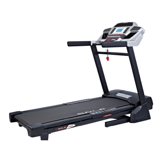
- Page 4 1. ST95 Treadmill Outlines...
- Page 5 Cooling FAN Speaker Console...
- Page 6 2. Electronic Parts...
- Page 7 2.1 Upper Controllers...
- Page 8 2.2. Lower Controller and Driver SPEED SENSOR DC MOTOR Incline Motor & VR Motor Controller Driver System(Motor/Controller/Incline Motor)
- Page 9 3. Electrical Configurations...
- Page 10 AFETY KEY To fits on the Console that activate all functions. If no safety key, console can not be controlled. ONSOLE Interface that controls all functions of the treadmill. AIN CONTROLLER The circuit board consist of the DC power supply for console、incline driver and DC motor driver, link the console to output appropriate voltages for motor that control the treadmill functions.
- Page 11 READMILL MOTOR It’s a variable speed on 0-90 volt DC motor.(for 110V model) Have three wires red, black and green. If there is DC voltage on the Red (white) wire (M+) the treadmill motor will turn clockwise. If there is DC voltage on the Black wire (M-) the treadmill motor will turn counter-clockwise. The higher the voltage the faster the motor turns The green wire is ground.
- Page 12 4. ST95 Treadmill Product Operation -12-...
-
Page 13: Display Windows
Display Windows 5.5” LCD Display -13-... - Page 14 LCD Layout -14-...
- Page 15 Operation Window Display Mode OFF Mode When user doesn’t insert the SAFETY KEY on the console, the treadmill enters the OFF Mode and all windows will appear blank. READY Mode When the treadmill is ON and SAFETY KEY is inserted in console, the message window will show "USE SPEED UP OR DOWN KEY TO SELECT A PROGRAM".
- Page 16 Incline Display the incline position from 0 to 15 DISPLAY range is 0 to 99. WORK range is 0 to 15. INCLINE preset value is 0 to 15. Press “UP” or ”DOWN” to adjust incline, each increment and decrement is 1. TIME TIME is either COUNT UP or COUNT DOWN.
- Page 17 Function Button Locations Speed quick keys Incline quick keys 1/2/4/6/8/10 2/4/6/8/10/12 Fan Key Cooling fan switch on or off Function Key Set data function Safety Key Emergency function -17-...
- Page 18 Function Button In Main Mode READY MODE SAFETY KEY: Fit safety key in right position to power on the computer. When safety key is pulled away from its position, the computer will be automatically shut down. STOP button: Non-function. START button: Pressing “ START ” button to start treadmill, When pressing “START” button, there will be 3 second final count down on window display, then machine starts running.
- Page 19 RUN MODE SAFETY KEY: When safety key is pulled away from its position, the computer will be automatically shut down. STOP button: press “STOP” button to stop treadmill. START button: non-functional. ENTER button: non-functional. FAST button: Press the button to increase your speed and each increase is 0.1kph(0.1mph). If button is pressed continuously then speed increases to MAX SPEED quickly.
-
Page 20: Unit Block Diagrams
5. Unit Block Diagrams -20-... - Page 21 Treadmill Configuration -21-...
- Page 22 6. Basic Connections and Wiring -22-...
- Page 23 6.1 Display Board wire Connections -23-...
- Page 24 6.2 Display Board PCB Component Locations PCB Board Top -24-...
- Page 25 PCB Board Bottom -25-...
- Page 26 6.3 Amplifier Board wire Connections -26-...
- Page 27 6.4 Driver Board Wire Connections -27-...
- Page 28 6.5 Driver Board PCB Component Locations -28-...
- Page 29 6.6 Driver Board LED Indicator Locations SHUT_DOWN POWER MOT_DRV LIMIT SPEED INC_DW (bottom PCB) INC_UP (bottom PCB) -29-...
- Page 30 6.7 Controller Indicator LED debugging Indicator Function Condition Reason Solve Motor speed Normal on when start is pressed. No input. Check fast/slow wires of 12PIN Fault condition if start is pressed & connector. LED off. Replace controller. Replace console. POWER Controller power If DC voltage is normal, it would be Voltage is not correct.
- Page 31 6.8 Driver Board function -31-...
- Page 32 7. Product Safety Instructions -32-...
-
Page 33: Important Safety Instructions
7.1 Important Safety Instructions - To reduce the risk of electric shock disconnect your treadmill from the electrical outlet prior to cleaning and/or service work. - To reduce the risk of burns, fire, electric shock, or injury to persons, install the treadmill on a flat level surface with access to a 230-volt, 10-amp grounded outlet with only the treadmill plugged into the circuit. - Page 34 8. Error Messages and Troubleshooting for Electronic Issues -34-...
- Page 35 Error code items: Error Message Explain LS1/LOW SPEED Display board CPU did not receive the RPM signal. E-1/RAM ERROR EEPROM failure The console board is not detecting the VR voltage value, or the INCLINE E2 voltage value has exceeded the range. Prepare:...
- Page 36 8.1 Error Message: : : : LS1/LOW SPEED Definition:Display board CPU did not receive the RPM signal. Configuration: -36-...
- Page 37 Cause of LS1/LOW SPEED The motor doesn’t turn:LS1/LOW SPEED appears. Explanation The drive board did not sent voltage to the motor, so the motor didn’t operate. And the display board didn’t receiver the RPM sensor signal. Configuration -37-...
- Page 38 LCD show LS1/LOW SPEED -38-...
- Page 39 LS1/LOW SPEED solution follow chart -39-...
- Page 40 Terminals for motor cable, Red for M+, Black for M- POWER LED PWM LED -40-...
- Page 41 LS1/LOW SPEED solution follow chart – check RPM sensor device procedure: : : : -41-...
- Page 42 Is sensor cable connected properly? Checking the speed sensor 1) Remove the motor cover hood. 2) The speed sensor is located on the left side of the frame, right next to the front roller pulley (the pulley will have a belt around it that also goes to the motor). The speed sensor is small and black with a wire connected to it.
- Page 43 LS1/LOW SPEED issue troubleshooting form LS1/LOW SPEED Possible cause Things to check Solution message The monitor hasn't receive any speed check the speed sensor cable is in good Make sure the good connection for signal for 8 seconds connection cables The speed sensor didn't detect signal Check the gap between speed sensor and To keep the gap-distance less than 3...
- Page 44 8.2 Error Message: : : : E1/RAM ERROR Definition: All screens are off, and outputs are stopped when EEPROM is damaged or malfunction. Display message will show “E-1”, and message window will show “RAM ERROR” Troubleshooting: Due to EEPROM error, restart treadmill or replace upper controller. -44-...
- Page 45 8.3 Error Message: : : : INCLINE E2 Definition:The console board is not detecting the VR voltage value, or the voltage value has exceeded the range.” INCLINE E2” appears on the display. Configuration: -45-...
- Page 46 LCD show INCLINE E2 -46-...
- Page 47 Case of INCLINE E2 Incline VR value exceeds the range. INCLINE E2 appears on the display. Incline motor isn’t operation up or down, making the VR value exceed the range. After turning on the unit, the display board detects that the incline VR voltage exceeds the range, so INCLINE E2 appears. Action Flow Chart -47-...
- Page 48 Troubleshooting Part Troubleshooting 1.Reconnect VR wires. Incline VR 2.Inspect whether the incline wires are broken or disconnected. 1.Inspect the incline wire and 12-pin cable connections. Display board 2.Test whether the VR voltage varies at the incline wire terminal. 1.Inspect the wire connections. 12-pin cable 2.Inspect whether wires are broken or crimped.
- Page 49 Test configuration. The console to driver board connector pin define function The console to driver board connector pin define function: 1. Controller S/ / / / W 2. Incline down output 3. Incline up output 4. Vin 5. Speed up output 6.
- Page 50 Test Configuration. Incline motor control function relate parts location 1. Controller S/ / / / W 2. Incline down output BLACK-DOWN 3. Incline up output 4. Vin White-NEUTRAL 5. Speed up output 6. Speed down output RED-UP 7. GND 8. GND 9.
- Page 51 Test Procedure: : : : Run calibration again. Does the incline motor move at all? If no, do the Up/down lights on the incline board light? If they light, do the relays click on? If the relay clicks on but the motor doesn’t move: with the incline light and relay activated check the voltage between the neutral (white) wire and the Up (red) or down (black) wire, depending on which direction the motor is supposed to travel according to Up/Down lights on the board.
- Page 52 Error Message: : : : INCLINE E2 Definition:During incline action, the display board CPU cannot read the VR value, so INCLINE E2 appears. Configuration: -52-...
- Page 53 Cause of INCLINE E2 Press the incline UP/DOWN key. The incline doesn’t operate. INCLINE E2 appears on the display. Explanation Press the incline UP and DOWN key. The driver board UP or DOWN indicator lights. The incline operates, moving the VR, which changes the VR value.
- Page 54 Troubleshooting Part Troubleshooting 1.Press incline UP key. The driver board UP LED lights. Display board 2.Press incline DOWN key. The driver board DOWN LED lights. 3.If not as above, inspect the cable and connections. 1.Inspect whether the 12-PIN cable is connected well. 12-pin cable 2.Test by replacing the cable with a good one.
-
Page 55: Circuit Diagram
8.4 Circuit diagram -55-... - Page 56 8.5 CALIBRATION PROCEDURE Calibration Turn on power. Press and hold “START” and “FAST” button at the same time. Inserts the SAFETY KEY on console, all windows will appear blank. Km/Mile Mode: Press “ENTER” button to enter calibration mode. Set wheel size: Press “FAST” or “SLOW” button to adjust SPEED window to 62. Press “ENTER”...
- Page 57 8.6 MAINTENANCE MENU 1. Press and hold the Start, Stop and Enter key at the same time, until the display shows “Engineering mode” (it may say maintenance menu, depending on version).Press the Enter key. 2. You can now scroll through the menu using the Speed ▲/▼ keys. Use the Stop key to return to previous menu selection.
-
Page 58: Fuse Replacement
8.7 Fuse replacement FUSE MOUNT FUSE 3 A If your treadmill loses power or will not start, check the fuse located on the motor controller. DANGER: Turn the power switch off and unplug the treadmill to reduce the risk of an electric shock Remove the motor cover Remove and replace the fuse on the motor controller Replace the motor cover... - Page 59 8.8 Troubleshooting procedure matrix Condition Reason Solve When turn on power, ON/OFF switch isn’t lit. 1 Power cord isn’t plugged into outlet. 1 Plug the power cord into outlet. 2 Power cord isn’t plug into unit. 2 Plug the power cord into unit. 3 The voltage of outlet is too low.
- Page 60 LCD displays not bright, incomplete or imperfect. 1. LCD displays are broken. 1. Replace with new console. When press “START” button to start treadmill, running 1. Controller experienced unusual shut down; 1. Turn off power and reset the treadmill. belt isn’t running and window displays “LS1/LOW the Shut_DOWN light will be always bright.
- Page 61 UP/DOWN button of 1 The connector of INCLINE CABLE 1 Connect the wires again. INCLINE ADJUSTMENT SWITCH can’t be used. and CONSOLE not connected properly. 2. The connector of INCLINE CABLE 2. Connect the wires again. and INCLINE ADJUSTMENT SWITCH Incline button just can press UP, can’t press DOWN.
- Page 62 9. Treadmill Folding/Unfolding and Transport -62-...
-
Page 63: Folding Instructions
FOLDING INSTRUCTIONS Do not attempt to move the unit unless it is in the folded and locked position. Be sure the power cord is secured to avoid possible damage. Use both handrails to maneuver the unit to the desired position. TO FOLD THE TREADMILL Lift the deck until the latch clicks in place. -
Page 64: General Maintenance
10. General Maintenance -64-... - Page 65 10.1 Tread belt and Deck Your treadmill uses a very high-efficient low-friction bed. Performance is maximized when the bed is kept as clean as possible. Use a soft, damp cloth or paper towel to wipe the edge of the belt and the area between the belt edge and frame. Also reach as far as practical directly under the belt edge.
- Page 66 TREAD-BELT TRACKING ADJUSTMENT The treadmill is designed so that the tread-belt remains reasonably centered while in use. It is normal for some belts to drift near one side while in use, depending on a user’s gait and if they favor one leg. But if during use the belt continues to move toward one side, adjustments are necessary. TO SET TREAD-BELT TRACKING A 6 mm Allen wrench (99)is provided for this adjustment.
- Page 67 BELT/DECK LUBRICATION Keeping the deck lubricated at the recommended intervals ensures the longest life possible for your treadmill. If the lubricant dries out, the friction between the belt and deck rises and places undue stress on the drive motor, drive belt and electronic motor control board, which could result in catastrophic failure of these expensive components.
- Page 68 11. Installation of the Incline Motor -68-...
- Page 69 Incline Range must be adjusted to 215mm minimum prior to installation. 215 mm -69-...
- Page 70 Take the old incline motor apart Use Allen wrench and 14mm before replacement. wrench to install the incline motor. Lay the treadmill as shown and use Allen wrench and 14mm wrench to install the incline Plug in cables onto the motor.
- Page 71 12. Disassembling and assembling of Parts -71-...
-
Page 72: Console Replacement
12.1 Lower Controller Replacement (1) Remove motor cover (2) Disconnect all lower controller wirings (3) Use Phillips head Screwdriver to remove, replace with new lower controller and reconnect all wirings. 12.2 Console Replacement (1) When replacing console, use Phillips head screwdriver to remove screws below the console first. Disconnect console wirings and replace with new console. -
Page 73: Motor Replacement
12.3 Motor Replacement (1) Use Phillips head screwdriver to remove 5 Tapping screw securing the motor cover. (2) Remove motor grounding wire (greenish yellow), motor wire (+) red and motor wire (-) black -73-... - Page 74 (3) Use 14mm T-shaped socket wrench to loosen 4 screws, use 14mm open end wrench to loosen 1 belt tension screw, remove motor and replace with new. (4) Reassemble in reverse order of disassembly, re-hook belt (readjust belt to be parallel with main frame after re-hooking). Do not tighten 4 securing screws yet.
- Page 75 12.4 Power Cord Replacement (1) Remove electrical connection wiring, replace part and reconnect wiring. 12.5 AC Power Switch Replacement (1) Disconnect wiring to AC power switch, replace AC power switch and reconnect wiring. -75-...
- Page 76 12.6 Front/ Rear Roller Replacement (1) Use Phillips head screwdriver to loosen 2 screws on the rear adjustment base. (2) Use M6 L Allen wrench to loosen 2 screws on the rear roller. (3) Remove motor cover, use 14mm T-shaped socket wrench to loosen 4 screws. Use 14mm open end wrench to loosen 1 belt tension screw and loosen drive belt.
- Page 77 (4) Use 13mm wrench to loosen front roller screws, remove front and back rollers, and replace with new. Reassemble in reverse order of disassembly. (5) When reassembled, running belt tension needs to be adjusted and centered. Belt tension also needs to be adjusted (refer to 12.3-5 above) -77-...
- Page 78 12.7 Running Deck/ Belt & Cushion Replacement (Please take the gas spring apart before replacement) (1) After running board has been folded, use Allen wrench to remove securing screws on gas spring cylinder and remove the cylinder. (2) Perform step #12.6 and remove front and rear rollers (3) Use Phillips head screwdriver to remove 4 sheet metal screws from the front and back of the foot rail according to the indicating arrows.
- Page 79 (4) User Phillips head screwdriver to remove the 8 screws securing the running board. Remove the running board and replace running board or running belt. If cushions need to be replaced, remove 6 cushions and replace. Reassemble in the reverse order as disassembly.
- Page 80 12.8 Speed Sensor Replacement (including the wire) (1) First remove motor top cover. (2) Remove speed sensor wiring and proceed with parts replacement. (3) After replacement, a test to check if the sensor registers the magnet is required. -80-...
- Page 81 12.9 Incline Motor Replacement (Zeroing the incline motor before take it apart from the machine or assemble it onto the frame. The zeroing distance is 215mm.) (1) . First adjust treadmill to folded position, then proceed with old incline motor replacement. (2) Use Phillips head screwdriver to assemble incline motor cover with incline motor -81-...
- Page 82 Use 14mm and 17mm wrench to assemble new incline motor. (3) Connect incline motor wiring with controller Red wire Connect to “UP” White wire Connect to ※ 紅 線 連 接 U P 端 “COM” 白 線 連 接 C O M 端 Black wire Connect to 黑...
Need help?
Do you have a question about the ST95-YT007 and is the answer not in the manual?
Questions and answers