Table of Contents
Advertisement
Quick Links
Advertisement
Table of Contents

Subscribe to Our Youtube Channel
Related Manuals for Dyaco XT660B-A912


Summary of Contents for Dyaco XT660B-A912
- Page 1 XT660B-A912 Treadmill Service Manual (110~120V & 220~230V)
-
Page 2: Table Of Contents
-------------------------------------------Table of Contents------------------------------------------- 1. Treadmill Outlines 2. Electronic Parts 2.1 Upper Controllers 2.2 Lower Controller and driver 3. Electrical Configuration 4. Treadmill Operation 5. Unit Block Diagrams 6. Basic Connections and Wiring 6.1 Display Board Wire Connections 6.2 Display Board PCB Component Locations 6.3 Amplifier Board Wire Connections 6.4 Driver Board Wire Connections 6.5 Driver Board PCB Component Locations... - Page 3 12.1 Lower Controller Replacement 12.2 Console Replacement 12.3 Motor Replacement 12.4 Breaker Replacement 12.5 AC Power Switch Replacement 12.6 Front/ Rear Roller Replacement 12.7 Running Deck/ Belt & Cushion Replacement 12.8 Speed Sensor Replacement 12.9 Incline Motor Replacement...
-
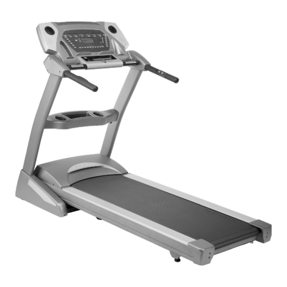
Page 4: Treadmill Outlines
1. Treadmill Outlines... - Page 5 Console Speed adjustment button Hand Pulse Sensor Incline adjustment button...
- Page 6 Driving Motor Lower Controller Incline Motor...
-
Page 7: Electronic Parts
2. Electronic Parts... -
Page 8: Upper Controllers
2.1 Upper Controllers Cooling FAN Speaker DISPLAY... -
Page 9: Lower Controller And Driver
2.2. Lower Controller and Driver INCLINE MOTOR DC MOTOR Motor Controller Driver System(Motor/Controller/Incline Motor) -
Page 10: Electrical Configuration
3. Electrical Configurations... - Page 11 AFETY KEY To fits on the Console that activate all functions. If no safety key, console can not be controlled. ONSOLE Interface that controls all functions of the treadmill. AIN CONTROLLER The circuit board consist of the DC power supply for console、incline driver and DC motor driver, link the console to output appropriate voltages for motor that control the treadmill functions.
- Page 12 READMILL MOTOR It’s a variable speed on 0-90 volt DC motor.(for 120V model) or 0-180 volt DC motor (for 220V model) Have three wires red, black and green. If there is DC voltage on the Red (white) wire (M+) the treadmill motor will turn clockwise. If there is DC voltage on the Black wire (M-) the treadmill motor will turn counter-clockwise.
- Page 13 4. Product Operation...
- Page 14 Display Windows 10 X 24 DOT MATRIX DISPLAY...
- Page 15 Operation Window Display Mode OFF Mode When user doesn’t insert the SAFETY KEY on the console, the treadmill enters the OFF Mode and all windows will appear blank. READY Mode When the treadmill is ON and SAFETY KEY is inserted in console, the message window will show program profile name and cycle. Press START button to start treadmill on Manual Mode.
- Page 16 LAPS Display the total working laps quantity. DISPLAY range is 0 to 99. WORK range is 0 to 99. Displays total laps quantity. DISTANCE Display the current distance in kilometer or Mile. DISPLAY range is 0.00 to 99.9. WORK range is 0.00 to 99.9. CALORIES Displays the cumulative calories burned at any given time during your workout.
- Page 17 Function Button Locations SPEED quick keys Incline quick keys PROGRAM keys Fan Key Cooling fan switch on or off Function Key Control operation Safety Key Emergency function...
- Page 18 Function Button In Main Mode READY MODE SAFETY KEY: Fit safety key in right position to power on the computer. When safety key is pulled away from its position, the computer will be automatically shut down. STOP button: Non-function. START button: Pressing “ START ” button to start treadmill, When pressing “START” button, there will be 3 second final count down on window display, then machine starts running.
- Page 19 RUN MODE SAFETY KEY: When safety key is pulled away from its position, the computer will be automatically shut down. STOP button: press “STOP” button to stop treadmill. START button: non-functional. FAST button: Press the button to increase your speed and each increase is 0.1kph(0.1mph). If button is pressed continuously then speed increases to MAX SPEED quickly.
-
Page 20: Unit Block Diagrams
5. Unit Block Diagrams... - Page 21 Treadmill Configuration...
-
Page 22: Basic Connections And Wiring
6. Basic Connections and Wiring... -
Page 23: Display Board Wire Connections
6.1 Display Board wire Connections... -
Page 24: Display Board Pcb Component Locations
6.2 Display Board PCB Component Locations PCB Board Top... - Page 25 PCB Board Bottom...
-
Page 26: Amplifier Board Wire Connections
6.3 Amplifier Board wire Connections... -
Page 27: Driver Board Wire Connections
6.4 Driver Board Wire Connections... -
Page 28: Driver Board Pcb Component Locations
6.5 Driver Board PCB Component Locations... -
Page 29: Driver Board Led Indicator Locations
6.6 Driver Board LED Indicator Locations SHUT_DOWN MOT_DRV POWER LIMIT INC_DW INC_UP... -
Page 30: Controller Indicator Led Debugging
6.7 Controller Indicator LED debugging Indicator Function Condition Reason Solve Motor speed Normal on when start is pressed. Fault No input. Check fast/slow wires of 12PIN condition if start is pressed & LED off. connector. Replace controller. Replace console. POWER Controller power If DC voltage is normal, it would be Voltage is not correct. -
Page 31: Driver Board Function
6.8 Driver Board function... -
Page 32: Product Safety Instructions
7. Product Safety Instructions... -
Page 33: Important Safety Instructions
7.1 Important Safety Instructions - To reduce the risk of electric shock disconnect your treadmill from the electrical outlet prior to cleaning and/or service work. - To reduce the risk of burns, fire, electric shock, or injury to persons, install the treadmill on a flat level surface with access to a 110-volt,15-amp(or 220-volt,10amp) grounded outlet with only the treadmill plugged into the circuit. -
Page 34: Error Messages And Troubleshooting For Electronic Issues
8. Error Messages and Troubleshooting for Electronic Issues... - Page 35 Error code items: Error Message Explain LS1/LOW SPEED Display board CPU did not receive the RPM signal. E-1/RAM ERROR EEPROM failure The console board is not detecting the VR voltage value,or the E2/INCLINE ERR voltage value has exceeded the range. Prepare:...
-
Page 36: Error Message: Ls1/Low Speed/Lose Speed
8.1 Error Message: : : : LS1/LOW SPEED/LOSE SPEED Definition:Display board CPU did not receive the RPM signal. Configuration:... - Page 37 Cause of LOW SPEED OR LOSE SPEED (LS) The motor doesn’t turn:LS1/LOW SPEED appears. Explanation The drive board did not sent voltage to the motor, so the motor didn’t operate. And the display board didn’t receiver the RPM sensor signal. Configuration...
- Page 38 LS/LS1/LOW SPEED solution follow chart -37-...
- Page 39 Terminals for motor cable, Red for M+, Black for M- PWM LED POWER LED -38-...
- Page 40 LS/LS 1/LOW SPEED solution follow chart – check RPM sensor device procedure: : : : -39-...
- Page 41 LS1/LOW SPEED issue troubleshooting form LS1/LOW SPEED Possible cause Things to check Solution message The monitor hasn't receive check the speed sensor cable Make sure the good any speed signal for 8 is in good connection connection for cables seconds To keep the The speed sensor didn't Check the gap between speed...
-
Page 42: Error Message: E1/Ram Error
8.2 Error Message: : : : E1/RAM ERROR Definition: All screens are off, and outputs are stop when EEPROM damaged or malfunction. Display message will show “E-1”, and message window will show “RAM ERROR” Troubleshooting: Replace upper controller. 8.3 Error Message: : : : INCLINE E2/Err Definition:The console board is not detecting the VR voltage value,or the voltage value has exceeded the range.”... - Page 43 Case of INCLINE E2 Incline VR value exceeds the range. INCLINE E2 appears on the display. Incline motor isn’t operation up or down, making the VR value exceed the range. After turning on the unit, the display board detects that the incline VR voltage exceeds the range, so INCLINE E2 appears.
- Page 44 Troubleshooting Part Troubleshooting 1. Reconnect VR wires. Incline VR 2. Inspect whether the incline wires are broken or disconnected. 1. Inspect the incline wire and 12-pin cable connections. Display board 2. Test whether the VR voltage varies at the incline wire terminal. 1.
- Page 45 Test configuration. The console to driver board connector pin define function The console to driver board connector pin define function: 1. Controller S/ / / / W 2. Incline down output 3. Incline up output 4. Vin 5. Speed up output 6.
- Page 46 Test Configuration. Incline motor control function relate parts location 1. Controller S/ / / / W 2. Incline down output 3. Incline up output 4. Vin 5. Speed up output 6. Speed down output 7. GND 8. GND The position sensor wires 9.
- Page 47 Test Procedure: : : : Run calibration again. Does the incline motor move at all? If no, do the Up/down lights on the incline board light? If they light, do the relays click on? If the relay clicks on but the motor doesn’t move: with the incline light and relay activated check the voltage between the neutral (white) wire and the Up (red) or down (black) wire, depending on which direction the motor is supposed to travel according to Up/Down lights on the board.
- Page 48 Error Message: : : : INCLINE E2 OR Err Definition:During incline action, the display board CPU cannot read the VR value, so INCLINE E2 appears. Configuration: -47-...
- Page 49 Cause of INCLINE E2 OR Err Press the incline UP/DOWN key. The incline doesn’t operate. INCLINE E2 appears on the display. Explanation Press the incline UP and DOWN key. The driver board UP or DOWN indicator lights. The incline operates, moving the VR, which changes the VR value.
- Page 50 Troubleshooting Part Troubleshooting 1.Press incline UP key. The driver board UP LED lights. Display board 2.Press incline DOWN key. The driver board DOWN LED lights. 3.If not as above, inspect the cable and connections. 1.Inspect whether the 12-PIN cable is connected well. 12-pin cable 2.Test by replacing the cable with a good one.
-
Page 51: Circuit Diagram
8.4 Circuit diagram(120V / 230V) -50-... -
Page 52: Calibration Procedure
8.5 CALIBRATION PROCEDURE 1. Remove the Safety Key. ▲ ▲ 2. Press and hold down the Start and Speed buttons and replace the Safety Key. Continue to hold the Start and Speed key until the window displays “Factory settings”, then press the Enter key. ▲/▼... -
Page 53: Maintenance Menu
8.6 MAINTENANCE MENU 1. Press and hold the Start, Stop and Enter key at the same time, until the display shows “Engineering mode” (it may say maintenance menu, depending on version).Press the Enter key. 2. You can now scroll through the menu using the Speed ▲/▼ keys. Use the Stop key to return to previous menu selection. - Page 54 8.7 Troubleshooting procedure matrix Condition Reason Solve 1 Power cord isn’t plugged into outlet. 1 Plug the power cord into outlet. When turn on power, ON/OFF switch isn’t lit. 2 Power cord isn’t plug into unit. 2 Plug the power cord into unit. 3 The voltage of outlet is too low.
- Page 55 LCDs not bright, incomplete or imperfect. 1. LCD light is broken. 1. Replace with new LCD or console. 2. Power to console too low. 2. Check AC power is 110V( for 220V model is 220V). 3. Check power to console. 4.Replace lower controller.
- Page 56 SPEED ADJUSTMENT SWITCH W/CABLE not connected properly. 3 The connector of SPEED CABLE or 3. Connect cable again. SPEED ADJUSTMENT SWITCH/W/CABLE is damaged. 4. Replace with new buttons. 4. Button of SPEED ADJUSTMENT SWITCH is broken. 5. Replace with new cable. 5.
- Page 57 connecting the HANDPULSE W/WIRE 4. Replace console or Hand pulse board. and Console. 4. Hand pulse board is broken. Wireless lost its function. 1. Chest belt not worn properly. 1. Check chest belt has proper contact with skin and is (No pulse displayed on monitor) oriented correctly.
-
Page 58: Treadmill Folding/Unfolding And Transport
9. Treadmill Folding/Unfolding and Transport -57-... - Page 59 FOLDING INSTRUCTIONS Do not attempt to move the unit unless it is in the folded and locked position. Be sure the power cord is secured to avoid possible damage. Use both handrails to maneuver the unit to the desired position. TO FOLD THE TREADMILL Make certain the treadmill is at minimum incline.
-
Page 60: General Maintenance
10. General Maintenance -59-... -
Page 61: Tread Belt And Deck
10.1 Tread belt and Deck Your treadmill uses a very high-efficient low-friction bed. Performance is maximized when the bed is kept as clean as possible. Use a soft, damp cloth or paper towel to wipe the edge of the belt and the area between the belt edge and frame. Also reach as far as practical directly under the belt edge. - Page 62 Tighten the rear roller bolts only enough to prevent slippage at the front roller. Turn both tread-belt tension adjustment bolts in increments of 1/4 turn each and inspect for proper tension by walking on the belt at a low speed, making sure the belt does not slip. Keep tensioning the bolts until the belt stops slipping.
- Page 63 ATTENTION: DAMAGE TO THE RUNNING BELT RESULTING FROM IMPROPER TRACKING / TENSION ADJUSTMENTS IS NOT COVERED UNDER THE WARRANTY. BELT/DECK LUBRICATION First, you want to clean between the belt and deck to remove any debris that may be trapped. Use a clean, non-fraying rag, t-shirt, or light towel. Halfway between the end of the treadmill and motor cover, shove the garment under the belt until you can grasp it on both sides of the belt.
- Page 64 10.2. Service Troubleshooting Checklist – Diagnosis Guide Before contacting your dealer for aid, please review the following information. It may save you both time and expense. This list includes common problems that may not be covered under the treadmill’s warranty. PROBLEM SOLUTION/CAUSE Display does not light...
- Page 65 Treadmill will only achieve approximately This indicates motor should be receiving power to operate. Low AC voltage to treadmill. Do not use an extension cord. 10 kph but shows higher speed on display If an extension cord is required it should be as short as possible and heavy duty 16 AWG minimum. Low household voltage. Contact an electrician or your dealer.
-
Page 66: Installation Of The Incline Motor
11. Installation of the Incline Motor -65-... - Page 67 Incline Range must be adjusted to 225mm minimum prior to installation. -66-...
-
Page 68: Disassembling And Assembling Of Parts
12. Disassembling and assembling of Parts -67-... -
Page 69: Lower Controller Replacement
12.1 Lower Controller Replacement (1) Remove motor cover (2) Disconnect all lower controller wirings (3) Use Phillips head Screwdriver to remove, replace with new lower controller and reconnect all wirings. -68-... -
Page 70: Console Replacement
12.2 Console Replacement (1) When replacing console, use Phillips Head Screw Driver to remove 6 Phillips Head Screw, Bolt Access Caps and the left and right handlebar covers. Use M5 L Allen wrench to remove 4 button head socket bolts, 2 flat Washers and 2 star Washers from the console support. Disconnect console wirings and replace with new console. -
Page 71: Motor Replacement
12.3 Motor Replacement (1) Use Phillips head screwdriver to remove 5 Tapping screw securing the motor cover. (2) Remove motor grounding wire (greenish yellow), motor wire (+) red and motor wire (-) black. -70-... - Page 72 (3) Use 14mm T-shaped socket wrench to loosen 4 screws, use 14mm open end wrench to loosen 1 belt tension screw, remove motor and replace with new. (4) Reassemble in reverse order of disassembly, re-hook belt (readjust belt to be parallel with main frame after re-hooking). Do not tighten 4 securing screws yet.
-
Page 73: Breaker Replacement
12.4 Breaker Replacement Remove Breaker connection wiring, replace part and reconnect wiring. -72-... -
Page 74: Ac Power Switch Replacement
12.5 AC Power Switch Replacement (1) Disconnect wiring to AC power switch, replace AC power switch and reconnect wiring. -73-... -
Page 75: Front/ Rear Roller Replacement
12.6 Front/ Rear Roller Replacement (1) Use Phillips head screwdriver to loosen 2 screws on the rear adjustment base. (2) Use M6 L Allen wrench to loosen 2 screws on the rear roller. -74-... - Page 76 (3) Remove motor cover, use 14mm T-shaped socket wrench to loosen 4 screws. Use 14mm open end wrench to loosen 1 belt tension screw and loosen drive belt. (4) Use 13mm wrench to loosen front roller screws, remove front and back rollers, and replace with new. Reassemble in reverse order of disassembly.
-
Page 77: Running Deck/ Belt & Cushion Replacement
12.7 Running Deck/ Belt & Cushion Replacement(Please take the cylinder before replacement) (1) After running board has been folded, use M5 Allen wrench and 12m/m wrench to remove securing screws on cylinder and remove the cylinder. (2) Perform step #12.6 and remove front and rear rollers. (3) Remove left and right Foot Rail Caps then use Phillips head screw driver to release six Concave Washers w/Screws and take apart Concave washers which secure the Foot Rail. - Page 78 -77-...
- Page 79 (4) User M5 Allen wrench to remove the 8 screws securing the running board. Remove the running board and replace running board or running belt. If cushions need to be replaced, remove 6 cushions and replace. Reassemble in the reverse order as disassembly.
-
Page 80: Speed Sensor Replacement
12.8 Speed Sensor Replacement(including the wire) (1) First remove motor top cover. (2) Remove speed sensor wiring and proceed with parts replacement. (3) After replacement, a test to check if the sensor registers the magnet is required. -79-... -
Page 81: Incline Motor Replacement
12.9 Incline Motor Replacement Zeroing the incline motor before take it apart from the machine or assemble it onto the frame. The ※ ※ ※ ※ zeroing distance is 225mm.) (1) . First adjust treadmill to folded position, then proceed with old incline motor replacement. -80-... - Page 82 (2) Use M6 Allen wrench, M8 Allen wrench and 14mm wrench to assemble new incline motor. -81-...
- Page 83 (3) Connect incline motor wiring with controller Red wire Connect to “UP” White wire Connect to “COM” Black wire Connect to “DOWN” -82-...
Need help?
Do you have a question about the XT660B-A912 and is the answer not in the manual?
Questions and answers