
Subscribe to Our Youtube Channel
Related Manuals for Dacor DHD30M967WM


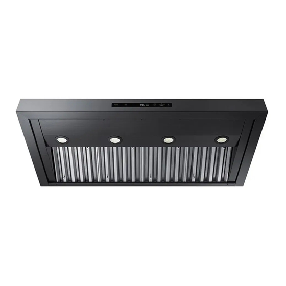
Summary of Contents for Dacor DHD30M967WM
- Page 1 Installation Instructions Modernist Range Hood DHD30M967WM, DHD36M976WM, DHD48M987WM, DHD30M967WS, DHD36M976WS, DHD48M987WS Part No. 110452 RevB...
- Page 2 Installing the Support Brackets Blower Rotation (Rear Exhaust) Remove and Replace parts Assembling the Filters Using the Dual-to-Single Transition Kit #AHT10 Hanging the Hood Hardwiring the Hood Inserting Light Bulbs Attaching the Dacor Badge Verifying the Setup Wiring Diagram English...
-
Page 3: Before You Begin
Before you begin... Important Installer • In the interest of safety and to minimize problems, read these installation instructions completely and carefully before you begin the installation process. • Leave these installation instructions with the customer. Customer • Keep these installation instructions for future reference and the local electrical inspector’s use. -
Page 4: Customer-Service Information
(Remove the filters to view the data plate.) All specifications are subject to change without notice. Dacor assumes no liability for changes to specifications. © 2017 Dacor, all rights reserved. -
Page 5: Important Safety Instructions
Use common sense and caution when installing, maintaining or operating this or any other appliance. • Always contact the Dacor Customer Service Team about problems and conditions that you do t understand. - Page 6 • Use the hood only as outlined in this manual. Do NOT use the hood to vent hazardous/ explosive materials or vapors. If you have questions, contact Dacor (contact info on Pg. • If you receive a damaged product, immediately contact your dealer/builder. Do not install/use a damaged hood.
- Page 7 • Do not install/repair/replace any part of the range hood unless specifically recommended by the procedures in this guide. A qualified service technician should perform all other service. Contact the nearest Dacor authorized service representative at (800) 793-0093, or at www.dacor.com for examination, repair or adjustment.
- Page 8 Important safety instructions WARNING • TO REDUCE RISK OF PERSONAL INJURY FROM A GREASE FIRE: - CAREFULLY SMOTHER FLAMES with a close-fitting lid, cookie sheet, or metal tray, then turn off the burner. If the flames do not die immediately, EVACUATE, THEN CALL THE FIRE DEPARTMENT.
-
Page 9: Installation Requirements
Installation requirements Checklist Use this checklist to verify that you have completed each step of the installation process. This can help you avoid mistakes. WARNING • To ensure a safe, correct installation, this checklist should be completed by the installer. •... - Page 10 Wire connector caps 8” Ducting Wire stripper Foil tape Drill, bits Sheet-metal screws Dual-to-Single Vent Transition Kit (option) Dacor Kit #AHT10 (Model DHD48 only) Sheet-metal screws 10” Ducts, ducting material Foil tape Drill, bits Blower Rotation (option) Phillips screwdriver 5/16” Nut driver...
- Page 11 48” (4), 36” (3), 30” (2) Holding brackets, Hardware Dimmable LED light bulbs Light-replacement tool (1) 48” (4), 36” (3), 30” (2) Product literature** (2) Dacor cleaning cream (1 stainless steel units only * Ready-to-assemble kit ** Installation instruction, User manual. English 11...
-
Page 12: Installation Planning
Installation requirements Installation Planning • A qualified technician must complete the installation of this built-in appliance. Proper installation is the customer's responsibility. • Carefully check the location where the Hood is to be installed. The Hood should be placed for convenient access. Make certain that electrical power can be provided in the selected location. - Page 13 Individual Models: DHD30/36/48 Components 48” 36” 30” Lights Filters Blowers Exhaust Vents Blower Rating 1200 CFM 600 CFM 600 CFM Weight Specifications Individual Models: DHD30/36/48 Model Weight 53 lbs (24 kg) 57 lbs (26 kg) 77 lbs (35 kg) Individual Models: DHD30/36/48 Model Top Vent Rear Vent...
- Page 14 Installation requirements Electrical/Ductwork Connections Connect electrical wires and ductwork through the top or rear of the hood. Before installing the hood, mark the access holes according to the diagrams below. (Tolerances: +1/16” -0”, unless otherwise stated.) Top Connections: All models Dual-Exhaust Standard 8"...
- Page 15 Rear Connections: All models 19 3/4 in. (2) Electrical- (50.2 cm) Access Holes Hood 9 7/8 in. 7/8 in. (5.1 cm) dia. (25.1 cm) 5 3/4 in. (14.6 cm) *See table Single-Exhaust Standard 8" duct Dual-Exhaust Hood bottom Standard 8" duct Dimensions: Rear Electrical Access Holes (DHD 30/36/48) Model 1”...
- Page 16 Installation requirements Dimensions (Hood) Tolerances: +1/16” -0” unless otherwise stated. Single Blower DHD30/36 Series Dual Blower DHD48 Series DHD Hood Dimensions Model 29 7/8” (75.9 cm) 24” 18” ” 35 7/8” (91.1 cm) (61 cm) (45.7 cm) (30. 47 7/8” (121.6 cm) English...
- Page 17 Cabinet-Layout Dimensions All tolerances: +1/16” -0”, unless otherwise stated. Electrical access (top and back of hood) * hood 30" min. bottom to (76.2 cm) cooking surface Min. Width of E (Upper-Cabinet Cutout, Appliance Width) Model DHD 30” (76.2 cm) 36” (91.5 cm) 48”...
-
Page 18: Installation Instructions
Installation instructions Meeting Electrical Codes • The owner shall verify that all electrical requirements are met by the qualified electrician servicing this appliance. • The electrical installation (incl. minimum supply-wire size and grounding) must comply with the National Electric code ANSI/NFPA (or latest revision), and local codes. Obtain a copy of the ANSI/NFPA standard from: - National Fire Protection Association 1 Batterymarch Park... -
Page 19: Preparation And Setup
Preparation and Setup This diagram shows the top and rear locations for wire access into the hood. See Wiring Diagrams at the end of this Top Access document. Rear Access Installing the Electrical Source In compliance with local codes, install an electrical junction box near the hood’s wiring access holes. -
Page 20: Meeting Installation Requirements
Installation instructions Meeting Installation Requirements • The hood must be at least as wide as the cooktop. • All dimensions must meet or exceed specified minimums. • Dimensions given are minimum clearances unless otherwise noted. • All contact surfaces between the hood and cabinetry/walls must be sturdy, solid, and at right angles. -
Page 21: Planning The Ductwork
• All ductwork material (incl. screws and foil tape) must be purchased by the customer. • Ductwork must not interfere with floor joists or wall studs. • On dual-exhaust models, the two 8” exhausts may be merged into one 10” duct using Dacor ransition it AHT10. - Page 22 Installation instructions Duct-Length Calculation Table The type of duct determines the hood’s maximum straight duct length. To determine your maximum length, start with the duct run’s total max. length, then subtract all of the ductwork equivalent lengths. (See the chart.) Duct Type Max.
- Page 23 Ductwork Tips • Try to minimize transitions/turns/sharp angles (e.g., two staggered 45° angles are better than one sharp 90° angle). • Keep turns as far away from the hood exhaust as possible; keep as much space between bends as possible. •...
-
Page 24: Planning The Mounting Location
Installation instructions Planning the Mounting Location Holding brackets and hardware are provided to support the hood so you can permanently anchor it to the wall. The illustrations below show the purpose of the holding brackets and the support behind the wall. •... - Page 25 Exhaust-Duct Marking the Centerlines help These measurements/marks center and level the hood, mark the duct cutouts. Have a marking tool, tape measure, and level ready. Dual Exhaust Single Exhaust Cooktop Top-Exhaust Centerline 1. Position the hood as it will be when installed (e.g., for a top-vent installation, set the hood with the vents on top).
-
Page 26: Marking The Centerlines
Installation instructions Installing the Support Brackets CRITICAL: To avoid alignment issues during final installation, the brackets must not be over/under/off the centerline. Step 4 Mounting block Bracket 2 1/8" (attached to placement studs inside wall behind hood) Line Stud Hood Area indicates (inside wall) hood top... -
Page 27: Blower Rotation (Rear Exhaust)
Blower Rotation (Rear Exhaust) IMPORTANT: Perform this procedure before you hang the hood. WARNING • Install the hood only if the electrical service meets the hood’s specifications; the owner shall verify proper installation. • Observe all local codes during installation. Contact your local building department for details. -
Page 28: Remove And Replace Parts
Installation instructions Remove and Replace parts Disassembling Parts 1. Unhook and remove the grease channel. 2. (Taking care not to scratch the hood) Place the hood assembly on a large, flat surface. 3. Remove the duct collar from the hood Duct Collar (top of hood) top. - Page 29 Configuring the Blower/Vent L-Brackets Back of Hood Back of Hood Blower/Vent L-Bracket Default Blower Rotated Blower Blower/Vent Configuration: Configuration: L-Bracket Top vent open- Open rear vent- No rear vent No top vent 1. Unscrew, and remove the L-bracket that is in the default top-venting configuration. 2.
-
Page 30: Assembling The Filters
Installation instructions Finalizing the Rear-Vent Setup 1. Refasten the cable clamps and assembly to the hood. Duct collar 2. Connect the cable assembly to the blower’s I/O port. Rear Right 3. Attach the duct collars to the back of the hood. 4. -
Page 31: Using The Dual-To-Single Transition Kit #Aht10
2" (5.1 cm) exhausts can be transitioned into one 10” 13 3/4" duct. (34.9 cm) Assemble the Dacor transition kit #AHT10 (sold separately) before you hang the 3/4" hood. This transition kit fits over the top/ (1.9 cm) rear ventilation exits. - Page 32 Installation instructions Installing the AHT10 Transition Kit Top-/Rear-Vent Configuration This procedure instructs you how to install the AHT10 ransi it for top- and rear- vent configurations NOTE The transition kit does not include the sheet-metal screws needed to install the hood. Top-Vent Configuration Rear-Vent Configuration 1.
-
Page 33: Hanging The Hood
Hanging the Hood WARNING Hanging the range hood requires two people. Do not lift the hood unassisted. IMPORTANT: Take care not to scratch/damage the hood. IMPORTANT: Hanging slots in the hood back engage the holding brackets to support the hood temporarily during installation. 1. -
Page 34: Hardwiring The Hood
Installation instructions Hardwiring the Hood Power may be suppled to the hood through an electrical junction box or a dedicated 15- Amp. circuit breaker. WARNING • Before connecting the wiring, turn OFF power to the hood at the fuse box or circuit breaker. - Page 35 3. With the provided green screw, attach the ground wire to the ground screw Neutral (white) inside (next to the main power switch above the filters hood Hot (black) IMPORTANT: Use a #10 O-ring at the end of the ground wire. Power To junction 4.
- Page 36 Installation instructions To house circuit Separate No. 10 (minimum) Separate No. 10 (minimum) To house circuit copper ground wire breaker panel or copper ground wire breaker panel or fuse box fuse box Meter Meter No. 4 copper No. 4 copper wire wire Wire nut,...
-
Page 37: Inserting Light Bulbs
Inserting Light Bulbs The electronic board was designed for dimmable bulbs. Using non-dimmable bulbs causes damage and faulty performance. If needed, clean the lens surface so the suction cup will stick to it. Perform this procedure for each hood light: 1. -
Page 38: Verifying The Setup
Installation instructions Verifying the Setup 1. Turn OFF the main power switch. 2. Turn power ON at the circuit-breaker panel or fusebox. 3. Turn ON the main power switch. The button panel flashes several times during startup. 4. (Taking care not to scratch the grease Main Power Grease channel o... - Page 39 Setup procedure again. IMPORTANT: If the hood still does not work, contact Dacor Distinctive Service: (800) 793-0093 x2822. Do not try to repair the hood yourself. Dacor is not responsible for service required to correct a faulty installation. English 39...
-
Page 40: Wiring Diagram
Installation instructions Wiring Diagram DHD30/36/48 WIRING DIAGRAM WIRE COLOR CODE W-WHITE DHD30, 36, 48 SERIES B-BLACK HOOD HOOD HOOD HOOD Y-YELLOW LED 7.5 W LED 7.5 W LED 7.5 W LED 7.5 W O-ORANGE (75 W MAX) (75 W MAX) (75 W MAX) (75 W MAX) R-RED... - Page 41 MEMO...
- Page 42 MEMO...
- Page 43 MEMO...
- Page 44 Dacor ∙ 14425 Clark Avenue, City of Industry, CA 91745 ∙ Phone: (800) 793-0093 ∙ Fax: (626) 403-3130 ∙ www.dacor.com...
Need help?
Do you have a question about the DHD30M967WM and is the answer not in the manual?
Questions and answers