
Related Manuals for Linde TPL 300 puls DC


Summary of Contents for Linde TPL 300 puls DC
-
Page 1: Operating Instructions
Operating instructions Power source TPL 300 puls DC TPL 300 puls AC/DC 099-000235-55801 Observe additional system documents! 06.11.2017... -
Page 2: General Instructions
For this reason, we do not accept any responsibility or liability for losses, damages or costs arising from incorrect installation, improper operation or incorrect usage and maintenance or any actions connected to this in any way. © Linde AG Gases Division Germany Seitnerstraße 70 82049 Pullach, Deutschland The copyright to this document remains the property of the manufacturer. - Page 3 Contents Notes on the use of these operating instructions Contents 1 Contents ................................3 2 For your safety ..............................5 Notes on the use of these operating instructions ................5 Explanation of icons ..........................6 Part of the complete documentation ....................7 Safety instructions ..........................
- Page 4 Disposing of equipment ........................31 7 Rectifying faults .............................32 Checklist for rectifying faults ......................32 Vent coolant circuit ..........................34 8 Technical data ..............................35 LINDE ARCLINE TPL 300 puls DC ......................35 ® LINDE ARCLINE TPL 300 puls AC/DC ....................36 ® 099-000235-55801...
-
Page 5: For Your Safety
For your safety Notes on the use of these operating instructions For your safety Notes on the use of these operating instructions DANGER Working or operating procedures which must be closely observed to prevent imminent serious and even fatal injuries. •... -
Page 6: Explanation Of Icons
For your safety Explanation of icons Explanation of icons Symbol Description Symbol Description Indicates technical aspects which the Activate and release/tap/tip user must observe. Switch off machine Release Switch on machine Press and keep pressed Switch Wrong Turn Numerical value – adjustable Correct Menu entry Signal light lights up in green... -
Page 7: Part Of The Complete Documentation
For your safety Part of the complete documentation Part of the complete documentation These operating instructions are part of the complete documentation and valid only in combination with all other parts of these instructions! Read and observe the operating instructions for all system components, especially the safety instructions! The illustration shows a general example of a welding system. - Page 8 For your safety Safety instructions WARNING Risk of injury from electrical voltage! Voltages can cause potentially fatal electric shocks and burns on contact. Even low voltages can cause a shock and lead to accidents. • Never touch live components such as welding current sockets or stick, tungsten or wire electrodes! •...
- Page 9 For your safety Safety instructions WARNING Explosion risk! Apparently harmless substances in closed containers may generate excessive pressure when heated. • Move containers with inflammable or explosive liquids away from the working area! • Never heat explosive liquids, dusts or gases by welding or cutting! Fire hazard! Due to the high temperatures, sparks, glowing parts and hot slag that occur during welding, there is a risk of flames.
- Page 10 For your safety Safety instructions CAUTION According to IEC 60974-10, welding machines are divided into two classes of electromagnetic compatibility (the EMC class can be found in the Technical data) > see 8 chapter Class A machines are not intended for use in residential areas where the power supply comes from the low-voltage public mains network.
- Page 11 For your safety Safety instructions Obligations of the operator! The respective national directives and laws must be complied with when operating the machine! • Implementation of national legislation relating to framework directive 89/391/EEC on the introduction of measures to encourage improvements in the safety and health of workers at work and associated individual guidelines.
-
Page 12: Transport And Installation
For your safety Transport and installation Transport and installation WARNING Risk of injury due to improper handling of shielding gas cylinders! Improper handling and insufficient securing of shielding gas cylinders can cause serious injuries! • Observe the instructions from the gas manufacturer and any relevant regulations concerning the use of compressed air! •... -
Page 13: Intended Use
Intended use Applications Intended use WARNING Hazards due to improper usage! The machine has been constructed to the state of the art and any regulations and standards applicable for use in industry and trade. It may only be used for the welding procedures indicated at the rating plate. -
Page 14: Service Documents (Spare Parts And Circuit Diagrams)
Intended use Documents which also apply Service documents (spare parts and circuit diagrams) 3.2.4 WARNING Do not carry out any unauthorised repairs or modifications! To avoid injury and equipment damage, the unit must only be repaired or modified by specialist, skilled persons! The warranty becomes null and void in the event of unauthorised interference. -
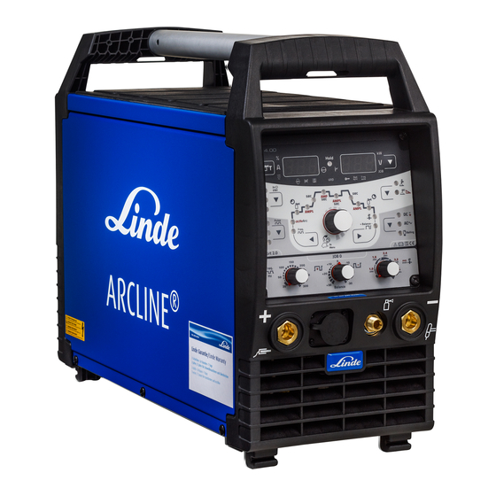
Page 15: Machine Description – Quick Overview
Machine description – quick overview Front view Machine description – quick overview Front view Figure 4-1 Item Symbol Description Carrying handle Machine control, see the relevant control operating instructions > see 5.2.1.1 chapter Connection socket, welding torch control cable Connection socket, "+" welding current •... -
Page 16: Rear View
Machine description – quick overview Rear view Rear view Figure 4-2 Item Symbol Description Connection socket, 19-pole Remote control connection 8-pole connection socket Cooling unit control lead 4-pole connection socket Cooling unit voltage supply Cooling air outlet Machine feet Mains connection cable >... -
Page 17: Design And Function
Design and function Transport and installation Design and function WARNING Risk of injury from electrical voltage! Contact with live parts, e.g. power connections, can be fatal! • Observe the safety information on the first pages of the operating instructions! • Commissioning must be carried out by persons who are specifically trained in handling power sources! •... -
Page 18: Machine Cooling
Design and function Transport and installation Machine cooling 5.1.2 Insufficient ventilation results in a reduction in performance and equipment damage. • Observe the ambient conditions! • Keep the cooling air inlet and outlet clear! • Observe the minimum distance of 0.5 m from obstacles! Workpiece lead, general 5.1.3 CAUTION... -
Page 19: Welding Torch Cooling System
Design and function Transport and installation Welding torch cooling system 5.1.5 Figure 5-2 Item Symbol Description 8-pole connection socket Cooling unit control lead 4-pole connection socket Cooling unit voltage supply Cooling module • Insert and lock the 8-pole control lead plug on the cooling unit into the 8-pole connection socket on the welding machine. -
Page 20: Notes On The Installation Of Welding Current Leads
Design and function Transport and installation Notes on the installation of welding current leads 5.1.6 Incorrectly installed welding current leads can cause faults in the arc (flickering). Lay the workpiece lead and hose package of power sources without HF igniter (MIG/MAG) for as long and as close as possible in parallel. -
Page 21: Stray Welding Currents
Design and function Transport and installation Figure 5-5 Stray welding currents 5.1.6.1 WARNING Risk of injury due to stray welding currents! Stray welding currents can destroy protective earth conductors, damage machines and electronic devices and cause overheating of components, leading to fire. •... -
Page 22: Mains Connection
Design and function Transport and installation Mains connection 5.1.7 DANGER Hazards caused by improper mains connection! An improper mains connection can cause injuries or damage property! • Only operate machine using a socket that has correctly fitted protective earth. • The mains voltage indicated on the rating plate must match the supply voltage. -
Page 23: Tig Welding
Design and function TIG welding TIG welding Welding torch and workpiece line connection 5.2.1 Prepare welding torch according to the welding task in hand (see operating instructions for the torch). Figure 5-8 Item Symbol Description Welding torch Welding torch hose package Connection socket, "-"... -
Page 24: Connection Assignment, Welding Torch Control Cable
Design and function TIG welding Connection assignment, welding torch control cable 5.2.1.1 TIG welding machines are equipped ex works with a dedicated connection socket for the welding torch control cable (5- or 8-pole). As mobile machines offer more free space, they may even feature two control cable connection sockets. -
Page 25: Connecting The Shielding Gas Supply
Design and function MMA welding Connecting the shielding gas supply 5.2.2.1 • Place the shielding gas cylinder into the relevant cylinder bracket. • Secure the shielding gas cylinder using a securing chain. Figure 5-10 Item Symbol Description Pressure regulator Shielding gas cylinder Output side of the pressure regulator Cylinder valve •... -
Page 26: Mma Welding
Design and function MMA welding MMA welding Connecting the electrode holder and workpiece lead 5.3.1 CAUTION Risk of crushing and burns! When changing stick electrodes there is a risk of crushing and burns! • Wear appropriate and dry protective gloves. •... -
Page 27: Pc Interface
Design and function PC interface PC interface Equipment damage or faults may occur if the PC is connected incorrectly! Not using the SECINT X10USB interface results in equipment damage or faults in signal transmission. The PC may be destroyed due to high frequency ignition pulses. •... -
Page 28: Remote Control Connection Socket, 19-Pole
Design and function Interfaces for automation Remote control connection socket, 19-pole 5.5.1 Figure 5-13 Pos. Signal shape Designation Output Connection for cable screen (PE) Output Current flows signal I>0, galvanically isolated (max. +- 15V/100mA) Output Reference voltage for potentiometer 10V (max. 10mA) Input Control value specification for main current, 0-10V (0V = I , 10V = I... -
Page 29: Maintenance, Care And Disposal
Maintenance, care and disposal General Maintenance, care and disposal General DANGER Risk of injury due to electrical voltage after switching off! Working on an open machine can lead to fatal injuries! Capacitors are loaded with electrical voltage during operation. Voltage remains present for up to four minutes after the mains plug is removed. -
Page 30: Maintenance Work, Intervals
Maintenance, care and disposal Maintenance work, intervals Maintenance work, intervals Daily maintenance tasks 6.3.1 Visual inspection • Mains supply lead and its strain relief • Gas cylinder securing elements • Check hose package and power connections for exterior damage and replace or have repaired by specialist staff as necessary! •... -
Page 31: Annual Test (Inspection And Testing During Operation)
Maintenance, care and disposal Disposing of equipment Annual test (inspection and testing during operation) 6.3.3 The welding machine may only be tested by competent, capable personsl. A capable person is one who, because of his training, knowledge and experience, is able to recognise the dangers that can occur while testing welding power sources as well as possible subsequent damage and who is able to implement the required safety procedures. -
Page 32: Rectifying Faults
Rectifying faults Checklist for rectifying faults Rectifying faults All products are subject to rigorous production checks and final checks. If, despite this, something fails to work at any time, please check the product using the following flowchart. If none of the fault rectification procedures described leads to the correct functioning of the product, please inform your authorised dealer. - Page 33 Rectifying faults Vent coolant circuit Bad arc ignition Material inclusions in the tungsten electrode due to contact with filler material or workpiece Regrind or replace the tungsten electrode Bad current transfer on ignition Check the setting on the "Tungsten electrode diameter/Ignition optimisation" rotary dial and increase if necessary (higher ignition energy).
-
Page 34: Vent Coolant Circuit
Rectifying faults Vent coolant circuit Vent coolant circuit Coolant tank and quick connect coupling of coolant supply and return are only fitted in machines with water cooling. To vent the cooling system always use the blue coolant connection, which is located as deep as possible inside the system (close to the coolant tank)! Figure 7-1 099-000235-55801... -
Page 35: Technical Data
Technical data LINDE ARCLINE® TPL 300 puls DC Technical data Performance specifications and guarantee only in connection with original spare and replacement parts! LINDE ARCLINE TPL 300 puls DC ® Setting range for welding current 5 A–300 A Setting range for welding voltage 10.2 V–22.0 V... -
Page 36: Linde Arcline ® Tpl 300 Puls Ac/Dc
Technical data LINDE ARCLINE® TPL 300 puls AC/DC LINDE ARCLINE TPL 300 puls AC/DC ® Setting range for welding current 5 A–300 A Setting range for welding voltage 10.2 V–22.0 V 20.2 V–32.0 V Max. welding current 30% DC 300 A...
Need help?
Do you have a question about the TPL 300 puls DC and is the answer not in the manual?
Questions and answers