Table of Contents
Advertisement
Quick Links
Thank you for choosing Air Conditioners, please read this owner‟s manual carefully
before operation and retain it for future reference.
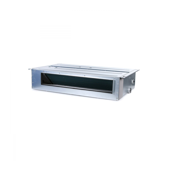
Multi Variable Air Conditioners
Ducted Type Indoor Unit
Owner's Manual
Air Conditioners
Models:
GMV-ND07PLS/A-T(U)
GMV-ND09PLS/A-T(U)
GMV-ND12PLS/A-T(U)
GMV-ND14PLS/A-T(U)
GMV-ND18PLS/A-T(U)
GMV-ND22PLS/A-T(U)
Advertisement
Table of Contents

Related Manuals for AC Pro GMV-ND07PLS-T


Summary of Contents for AC Pro GMV-ND07PLS-T
- Page 1 Multi Variable Air Conditioners Ducted Type Indoor Unit Owner's Manual Air Conditioners Models: GMV-ND07PLS/A-T(U) GMV-ND09PLS/A-T(U) GMV-ND12PLS/A-T(U) GMV-ND14PLS/A-T(U) GMV-ND18PLS/A-T(U) GMV-ND22PLS/A-T(U) Thank you for choosing Air Conditioners, please read this owner‟s manual carefully before operation and retain it for future reference.
- Page 3 Preface For correct installation and operation, please read all instructions carefully. Before reading the instructions, please be aware of the following items: This is the safety alert symbol. It is used to alert you to potential personal injury hazards. Obey all safety messages that follow this symbol to avoid possible injury or death.
-
Page 4: User Notice
User Notice This appliance is not intended for use by persons (including children) with reduced physical, sensory or mental capabilities, or lack of experience and knowledge, unless they have been given supervision or instruction concerning use of the appliance by a person responsible for their safety. - Page 5 Contents 1 Safety Precautions ................1 2 Product Introduction ................2 2.1 Names of Key Components ..............2 2.2 Rated Working Condition ................2 3 Preparations for Installation ..............3 3.1 Standard Fittings ..................3 3.2 Location for Installation ................3 3.3 Requirements for Communication Line ............
-
Page 6: Safety Precautions
(18) User is not allowed to repair the unit. Fault service may cause electric shock or fire accidents. Please contact AC PRO appointed service center for help. (19) Before installation, please check if the power supply is in accordance with the requirements specified on the nameplate. -
Page 7: Product Introduction
(26) If anything abnormal happens (such as burning smell), please power off the unit and cut off the main power supply, and then immediately contact AC PRO appointed service center. If abnormality keeps going, the unit might be damaged and lead to electric shock or fire. -
Page 8: Preparations For Installation
Multi Variable Air Conditioners Ducted Type Indoor Unit 3 Preparations for Installation Note! Product graphics are only for reference. Please refer to actual products. Unspecified measure unit is mm/in. 3.1 Standard Fittings Please use the supplied standard fittings listed below as instructed. Name Appearance Q'ty... -
Page 9: Requirements For Communication Line
Multi Variable Air Conditioners Ducted Type Indoor Unit (5) In order to make sure the space for maintenance, please install the indoor unit according to the dimension described below. (6) Keep the unit away from heating source, inflammable gas or smoke. (7) This is a concealed ceiling type unit. -
Page 10: Electric Installation
Multi Variable Air Conditioners Ducted Type Indoor Unit Total length of communication line between Wire size Material Material type Remarks indoor unit and /AWG) Standard wired controller L (m/ft.) 1. Total length of communication line can't exceed 250m (820-1/5ft.). Light/Ordinary 2. -
Page 11: Installation Instructions
Multi Variable Air Conditioners Ducted Type Indoor Unit (1) Use copper wire only as unit‟s power cord. Operating temperature should be within its rated value. (2) If the power cord is more than 15m (49-1/4 ft.) long, please increase properly the sectional area of power cord to avoid overload, which may cause accident. - Page 12 Multi Variable Air Conditioners Ducted Type Indoor Unit Below are dimensions of A, B, C, etc. for different models: Unit: mm/in. Model GMV-ND07 PLS/A-T(U) GMV-ND09 PLS/A-T(U) (29-1/4) (19-3/8) (27-1/2) (24-1/4) (7-7/8) (4-3/4) (20-3/4) (6-3/8) (22-7/8) GMV-ND12 PLS/A-T(U) GMV-ND14 PLS/A-T(U) (37-1/8) (19-3/8) (39-3/8) (24-1/4)
-
Page 13: Refrigerant Pipe Connection
Multi Variable Air Conditioners Ducted Type Indoor Unit (2) Install the indoor unit temporarily Assemble suspension bolt on the expansion bolt, attach the hanger bracket to the suspension bolt. Be sure to fix it securely by using a nut and washer from upper and lower sides of the hanger bracket. -
Page 14: Drainage Pipe Installation And Drainage System Testing
Multi Variable Air Conditioners Ducted Type Indoor Unit Fig.4.2.1 (3) Use pipe bend when bending the pipe and the bending angle should not be too small. (4) Wrap the connection pipe and joint with sponge and then tie them firmly with tape. 4.3 Drainage Pipe Installation and Drainage System Testing 4.3.1 Notice for Installation of Drain Pipe (1) The drainage pipe should be short and the gradient downwards should be at least... - Page 15 Multi Variable Air Conditioners Ducted Type Indoor Unit (2) Tighten the pipe clamp, with the distance between screw nut and hose smaller than 4mm (3/16 in.). ① metal clamp(accessory) ② drain hose(accessory) Fig 4.3.2 (3) Use sealing plate to make the pipe clamp and hose insulated, as shown in Fig.4.3.3. ①...
- Page 16 Multi Variable Air Conditioners Ducted Type Indoor Unit Fig 4.3.6 Fig 4.3.7 Fig4.3.8 (9) The installation height of raising pipe for drainage should be lower than B. The gradient from raising pipe towards drainage direction should be at least 1%~2%. If the raising pipe is vertical with the unit, the raising height should be less than C.
-
Page 17: Installation Of Air Duct
Multi Variable Air Conditioners Ducted Type Indoor Unit 1) In case of commissioning finished, please energize the IDUs and switch to cooling or dry mode, meanwhile, the water pump operates, you can check the draining through the transparent part of drain socket. 2) If communication wire is not connected, communication malfunction “C0”... - Page 18 Multi Variable Air Conditioners Ducted Type Indoor Unit 4.4.1 Installation of Air-out Duct (1) Installation of the Rectangular Duct Fig 4.4.1 Name Name Hanger Rod Static Pressure Box Return Air Duct Filter Screen Canvas Duct Main Supply Air Duct Return Air Inlet Supply Air Outlet (2) Installation of Circular Duct Fig 4.4.2...
- Page 19 Multi Variable Air Conditioners Ducted Type Indoor Unit Air-return Opening Fig 4.4.4 Size of Air Outlet Size of Air-return Opening Model A(mm/in.) B(mm/in.) C(mm/in.) D(mm/in.) GMV-ND07PLS/A-T(U) GMV-ND09PLS/A-T(U) 121(4-3/4) 528(20-3/4) 580(22-7/8) 161(6-3/8) GMV-ND12PLS/A-T(U) GMV-ND14PLS/A-T(U) 121(4-3/4) 728(28-5/8) 780(30-3/4) 161(6-3/8) GMV-ND18PLS/A-T(U) 121(4-3/4) 928(36-1/2) 980(38-5/8) 161(6-3/8) GMV-ND22PLS/A-T(U)
-
Page 20: Installation Of Wired Controller
Multi Variable Air Conditioners Ducted Type Indoor Unit Fig 4.4.8 Table 5 Installation of the return air duct Name Name Return Air Inlet (with filter) Indoor unit Canvas Duct Supply Air Duct Return Air Duct Grille 4.5 Installation of Wired Controller Please refer to User Manual of Wired Controller for the installation details. -
Page 21: Power Cord Connection
Multi Variable Air Conditioners Ducted Type Indoor Unit 3) Shape the tail of wire into ring by needle nose plier, and keep the gauge of ring in accordance with screw. 4) Use the screwdriver for tightening the terminal. (2) The connection of stranded wire (as shown in fig 5.1.2) 1) Strip about 10mm (3/8 in.) insulation of the end of stranded wire by stripping and cutting tool. -
Page 22: Connection Of Communication Wire Between Indoor Unit And Outdoor Unit (Or Indoor Unit)
Multi Variable Air Conditioners Ducted Type Indoor Unit 5.3 Connection of Communication Wire between Indoor Unit and Outdoor Unit (or indoor unit) (1) Detach the electric box lid. (2) Let the Communication cable pass through the wiring through-holes. (3) Connect the communication wire to terminal D1 and D2 of indoor 4-bit wiring board, as shown in fig5.3.1. - Page 23 Multi Variable Air Conditioners Ducted Type Indoor Unit Fig 5.4.3 5.5 Illuminate for Connection of Wired Controller and Indoor Units Network (1) Communication wire of indoor unit and outdoor unit (or indoor unit) is connected to D1, D2. (2) Wired controller is connected to H1, H2. (3) One indoor unit can connect two wired controllers that must be set as master one and slave one.
- Page 24 Multi Variable Air Conditioners Ducted Type Indoor Unit Fig 5.5.1...
-
Page 25: Routine Maintenance
Multi Variable Air Conditioners Ducted Type Indoor Unit 6 Routine Maintenance (1) Do turn off the unit and cut off the main power supply when cleaning the air conditioner to avoid electric shock or injury. (2) Stand at solid table when cleaning the unit. (3) Do not clean the unit with hot water whose temperature is higher than 45°C to prevent fade or deformation. -
Page 26: Troubleshooting
Multi Variable Air Conditioners Ducted Type Indoor Unit 7 Table of Error Codes for Indoor Unit Error Error Error Content Content Content Code Code Code Indoor Units Indoor Unit Error Jumper Cap Error Incompatibility Error Indoor Unit Network Indoor Fan Protection Low Air Quality Warning Address Error ODU-IDU Incompatibility... - Page 28 Add: Tel: E -mail:...
Need help?
Do you have a question about the GMV-ND07PLS-T and is the answer not in the manual?
Questions and answers