
Related Manuals for AC Pro AWH30LB-D3DNA3D/I


Summary of Contents for AC Pro AWH30LB-D3DNA3D/I
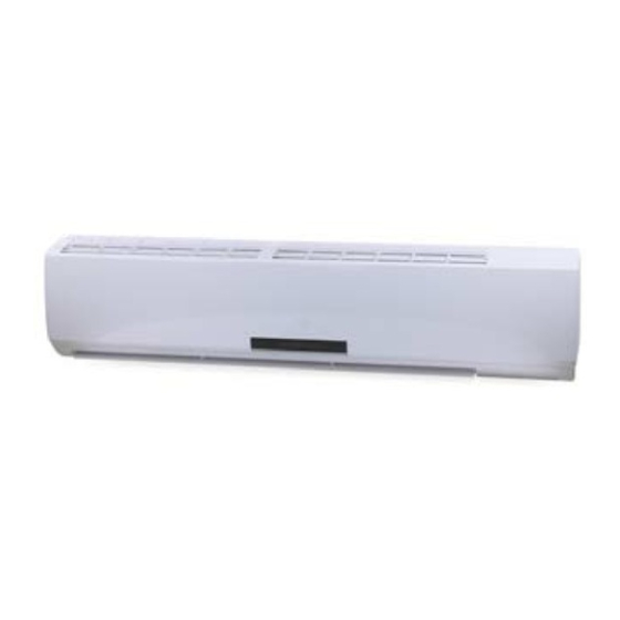
- Page 1 AC Pro S-Series 30-36K Manual Models AWH30LB-D3DNA3D/I AWH30LB-D3DNA3G/O AWH30LB-D3DNA3D/I AWH36LB-D3DNA3G/O (Refrigerant R410A)
- Page 2 We reserve the right to correct any clerical errors. Copyright 2018 AC Pro...
-
Page 3: Notes For Installation And Maintenance
PART I : INSTALLATION & MAINTENANCE . NOTES FOR INSTALLATION AND MAINTENANCE 10. If the power cord or power connection wire is not SAFETY PRECAUTIONS: long enough, replace with specialized cable from IMPORTANT! manufacturer before proceeding with installation or repair. DO NOT elongate these wires. Please read the safety precautions carefully before installation or prior to performing any maintenance. -
Page 4: Main Tools For Installation And Maintenance
MAIN TOOLS FOR INSTALLATION AND MAINTENANCE 1. Level, measuring tape 2. Screwdrivers 3. Impact drill, drill head, electric drill 4. Electroprobe 5. Universal meter 6. Torque wrench, open-end wrench, inner hexagon spanner 7. Electronic leakage detector 8. Vacuum pump 9. Pressure meter essure meter 10. -
Page 5: Installation
.0 INSTALLATION .1 Installation Dimension Diagram... - Page 6 Start installation Preparation before installation Read the requirements for Select installation location Prepare tools electric connection Select indoor unit Select outdoor unit installation location installation location Install the support of Install wall-mounting frame, outdoor unit drill wall holes (select it according to the actual situation) Connect pipes of indoor unit and drainage pipe...
-
Page 7: Electric Connection
.2 INSTALLATION PARTS CHECKING .4 REQUIREMENTS FOR ELECTRIC CONNECTION Name Name 1. Safety Precaution Indoor unit Sealing gum • Follow ALL electric safety requirements during Outdoor unit Wrapping tape installation. Connection pipe Support of outdoor • Use qualified power supply circuit and air switch – unit according to local safety regulations. - Page 8 • Choose position of piping hole according to the direction of 5. Indoor Unit Pipe Connect the outlet pipe. The position of the piping hole should be • Aim pipe to the corresponding bellmouth (Shown in Figure just slightly lower than the wall-mounted frame. (Shown in #5 below).
- Page 9 7. Bind up Pipe 6. Indoor Unit Wire Connection • Bind the connection pipe, power cord and drain hose with • Open panel. Remove screw on wiring panel and detach band. Shown in Figure #14 below). cover (Shown in Figure #11 below). •...
-
Page 10: Installation Of Outdoor Unit
Refer to the following table for wrench moment of force: .6 INSTALLATION OF OUTDOOR Hex nut diameter(inch) Tightening torque(ft·Ibf) UNIT 11.10~14.75 1. Support of Outdoor Unit 20.12~29.50 • Select according to actual installation situation. Select installation location according to the structure. 33.19~40.56 •... -
Page 11: Vacuum Pumping And Leak Detection
.8 CHECK AFTER INSTALLATION Note: • The through-wall height of drain hose should not be higher AND TEST OPERATION than the outlet pipe hole of the indoor unit (Shown in Figure #25 above). 1. Check after Installation • Angle drain hose slightly downward. Drain hose CANNOT be Check according to the following requirement after finishing curved or bent (Shown in Figure #26 above). -
Page 12: Troubleshooting
. Troubleshooting .1 Flashing LED of Indoor/Outdoor Unit and Primary Display Method of Outdoor Display Method of Indoor Unit Unit Indicator Display (during Indicator has 3 kinds of display blinking, ON 0.5s and OFF status and during blinking, ON Malfunction Possible 0.5s) 0.5s and OFF 0.5s... - Page 13 Display Method of Outdoor Display Method of Indoor Unit Unit Indicator Display (during Indicator has 3 kinds of display blinking, ON 0.5s and OFF status and during blinking, ON Malfunction Possible 0.5s) 0.5s and OFF 0.5s Dual 8 Name Status Causes Code Heat-...
- Page 14 Display Method of Outdoor Display Method of Indoor Unit Unit Indicator Display (during Indicator has 3 kinds of display blinking, ON 0.5s and OFF status and during blinking, ON Malfunction Possible 0.5s) 0.5s and OFF 0.5s Name Dual 8 Status Causes Code Heat-...
- Page 15 Display Method of Outdoor Display Method of Indoor Unit Unit Indicator Display (during Indicator has 3 kinds of display blinking, ON 0.5s and OFF status and during blinking, ON Malfunction Possible 0.5s) 0.5s and OFF 0.5s Name Dual 8 Status Causes Code Heat-...
- Page 16 Display Method of Outdoor Display Method of Indoor Unit Unit Indicator Display (during Indicator has 3 kinds of display blinking, ON 0.5s and OFF status and during blinking, ON Malfunction Possible 0.5s) 0.5s and OFF 0.5s Dual 8 Name Status Causes Code Heat-...
- Page 17 Display Method of Outdoor Display Method of Indoor Unit Unit Indicator Display (during Indicator has 3 kinds of display blinking, ON 0.5s and OFF status and during blinking, ON Malfunction Possible 0.5s) 0.5s and OFF 0.5s Name Dual 8 Status Causes Code Heat-...
- Page 19 Analysis of processing of some of the malfunction display: 1. Compressor discharge protection Possible reasons: shortage of refrigerant; blockage of air filter; poor ventilation or air flow shor pass for condenser; the system has noncondensing gas (such as air, water etc.); blockage of capillary assy (including filter); leakage inside four-way valve casuses incorrect operation;...
-
Page 20: How To Check Simply The Main Part
.2 How to Check Simply the Main Part Indoor Unit 1. Malfunction of Temperature Sensor F1, F2 Main detection points: Is the wiring terminal between the temperature sensor and the controller loosened or poorly contacted? Is there short circuit due to trip-over of the parts? Is the temperature sensor broken? Is mainboard borken? Malfunction diagnosis process:... - Page 21 2. Malfunction of Blocked Protection of IDU Fan Motor H6 Start Turn the fan blades by hand under power-off condition Adjust the motor and blade Whether the fan blades assembly so that rotor can run can run smoothly? smoothly. Turn unit on to check whether the malfunction is eliminated.
- Page 22 3. Malfunction of Protection of Jumper Cap C5 Main detection points: Is there jumper cap on the mainboard? Is the jumper cap inserted correctly and tightly? The jumper is broken? The motor is broken? Detection circuit of the mainboard is defined abnormal? Malfunction diagnosis process: Start eliminated...
- Page 23 4. Malfunction of Overcurrent Protection E5 Main detection points: Is the supply voltage unstable with big fluctuation? Is the supply voltage too low with overload? Hardware Trouble? Malfunction diagnosis process: Start eliminated eliminated eliminated eliminated model eliminated eliminated opened completely) eliminated...
- Page 24 5. Malfunction of Zero-Crossing Inspection Circuit Malfunction of the IDU Fan Motor U8 Main detection points: Instant energization after de-energization while the capacirot charges slowly? The zero-cross detection circuit of the mainboard is defined abnormal? Malfunction diagnosis process: Start U8 is still displayed...
- Page 25 6. Malfunction of Communication E6 Main detection points: Check if the connection wire and the built-in wiring of indoor and outdoor unit are connected well and without damage; If the communitcation circuit of indoor mainboard is damaged? if the communication circuit of outdoor main- board (AP1) is damaged? Malfunction diagnosis process: Start...
- Page 26 Outdoor Unit (1) Capacitor charge fault (Fault with outdoor unit) (AP1 below refers to the outdoor control panel) Main Check Points: Use AC voltmeter to check if the voltage between terminal L and N on the wiring board is within 210VAC- 240VAC If the reacotr (L) is correctly connected? If the connection is loose or fallen? If the reactor (L) is damaged? Fault diagnosis process.
- Page 27 (2) IPM Protection, Out-of-step Fault, Compressor Phase Overcurrent (AP1 below refers to the outdoor control panel) Main check points: If the connection between control panel AP1 and compressor COMP is secure? If loose? If the connection is in correct order? If the voltage input of the machine is within normal range? (Use AC voltmeter to measure the voltage between terminal L and N on the wiring board XT) If the compressor coil resistance is normal? If the insulation of compressor coil against the copper tube is in...
- Page 28 (3)High temperature and overload protection diagnosis (AP1 hereinafter refers to the control board of the out- door unit) Mainly detect: Is outdoor ambient temperature in normal range? Are the outdoor and indoor fans operating normally? Is the heat dissipation environment inside and outside the unit is good? Overheat and high temperature protection Normal protection, please operate...
- Page 29 (4) Start-up failure (following AP1 for outdoor unit control board) Mainly detect: Whether the compressor wiring is connected correct? Is compressor broken? Is time for compressor stopping enough? Power on the unit Restart it up after Is stop time of the compressor 3 minutes longer than 3 minutes? Does startup fail?
- Page 30 (5) Out of step diagnosis for the compressor (AP1 hereinafter refers to the control board of the outdoor unit) Mainly detect: Whether the system pressure is too high? Whether the input voltage is too low? Out of step occurs in Out of step occurs once the operation unit is powered on.
- Page 31 (6)Overload and air exhaust malfunction diagnosis (following AP1 for outdoor unit control board) Mainly detect: Wether the PMV is connected well or not? Is PMV damaged? Is refrigerant leaked? 20 minutes after the complete unit is powered off Is the terminal FA for the Connect the electronic expansion valve wires correctly...
- Page 32 (7)Power factor correct or (PFC) fault (a fault of outdoor unit) (AP1 hereinafter refers to the control board of the outdoor unit) Mainly detect: Check if the reactor (L) of the outdoor unit and the PFC capacitor are broken Start Check wiring of the reactor (L) of the outdoor unit and the...
- Page 33 (8) Communication malfunction: (following AP1 for outdoor unit control board) Mainly detect: Is there any damage for the indoor unit mainboard communication circuit? Is communication circuit damaged? Detect the indoor and outdoor units connection wire and indoor and outdoor units inside wiring is connect well or not, if is there any damage? Start Did the equipment operate...
- Page 34 (9) Communication malfunction:(following AP1 for outdoor unit control board) Mainly detect: Detect the indoor and outdoor units connection wire and indoor and outdoor units inside wiring is connect well or not, If is there any damage? Is there any damage for the indoor unit mainboard communication circuit? Is communication circuit damaged? The flow chart for malfunction detect: Start Did the equipment operate...
- Page 35 (10) High-Pressure Protection High-pressure protection Use pressure gauge to Measure if the pressure switch Replace the mainboard of measure if the pressure is is normal outdoor unit really high? Check if the operation mode of Set the correct operation Replace the pressure switch indoor unit is set properly? mode Check if the gas valve and...
-
Page 36: Troubleshooting For Normal Malfunction
.3 TROUBLESHOOTING FOR NORMAL MALFUNCTION Discriminating Method 1. Air Conditioner Cant be Started Up Possible Causes Troubleshooting (Air conditioner Status) Confirm whether its due to power failure. If yes, wait for No power supply, or poor connection for After energization, operation indicator isnt power recovery. - Page 37 4. ODU fan motor cant operate Discriminating Method Possible Causes Troubleshooting (Air conditioner Status) Check the wiring status according to circuit Connect wires according to wiring diagram to make sure all Wrong wire connection, or poor connection diagram wiring terminals are connected firmly Measure the capacity of fan capacitor with an universal meter and find that the capacity Capacity of the ODU fan motor is damaged...
-
Page 38: Exploded View And Parts List
. EXPLODED VIEW AND PARTS LIST .1 Indoor Unit... - Page 39 Part Code Description AWH30LB-D3DNA3G/I AWH36LB-D3DNA3G/I Product Code CB171N10600 CB171N10800 Receiver Window 22432164 22432164 Front Panel 20012490S 20012490S Stand Bar 24212120 24212120 Filter Sub-Assy 11122106 11122106 Front Case Sub-Assy 20022159 20022159 Upper Guide Louver 10512166 10512166 Lower Guide Louver 10512167 10512167 Axile Bush 10542704 10542704...
- Page 40 AWH30LB-D3DNA3G/0 AWH36LB-D3DNA3G/0 11 12 13 14 15...
- Page 41 Part Code Description AWH30LB-D3DNA3G/O AWH36LB-D3DNA3G/O Product Code CB171W10600 CB171W10800 Front Grill 01473050 01473050 Cabinet 0143500401P 0143500401P Front Side Plate 01303249P 01303249P Axial Flow Fan 10335014 10335014 Drainage Plug 06813401 06813401 Chassis Sub-Assy 02803101P 02803026P Drainage Connecter 06123401 06123401 Compressor Gasket 76715022 76710207 Compressor and fittings...
-
Page 42: Removal Procedure
. REMOVAL PROCEDURE .1 Removal Procedure of Indoor Unit Steps Procedure 1. Before disassembly of the unit axonometric drawing for the complete unit. 2. Remove Filter panel Open the Panel. Loosen the clasps on the filter clasps filter Draw out two pieces of filter. - Page 43 Steps Procedure 3. Remove Display display Remove 2 screws fixing display, and then remove the filter 4. Remove Panel clasp Pull the clasps at both sides slightly, and then remove the panel panel 5. Remove Horizontal Louver Remve the axial bush on the horizontal louver, and then remove the horizontal louver.
- Page 44 Steps Procedure 6. Remove Top Cover of Electric Box Remove screws fixing the top cover of screw electric box. Remove the top cover of electric box. top cover of electric box 7. Remove Front Case screw cap Remove the screw caps on front case. screw Remove screws connecting the front case...
- Page 45 Steps Procedure 8. Remove earthing wire screw Remove earthing screws, and then remove the earthing wire. 9. Remove elextric box cover clasp Loosen clasps at the left side of electric box. clasp Lossen clasps on the right side of elec- tric box.
- Page 46 Steps Procedure 10. Remove Temperature Sensor Pull out the indoor temperature sensor. temperature sensor 11. Remove Electric Box Pull out 6 sockets on PCB board. Pull out two scews on electric box. screw electric bo Remove electric box.
- Page 47 Steps Procedure 12. Remove Water Tray water tray Pullthe water tray upwards, and then remove the water tray. 13. Remove connection pipe between indoor and outdoor units Seperate the connection pipe between indoor and outdoor units. connection position for indoor and outdoor units' connection pipe 14.
- Page 48 Steps Procedure 16. Remove Evaporator screw Remove screws between evaporator and bottom case. Turn over the indoor unit and adjust the pipe line to the position as shown by the broken line. Lift up the evaporator, and then remove the evaporator evaporator 17.
- Page 49 Steps Procedure 18. Remove cross flow blade and motor blade motor Remove screws fixing cross flow blade and motor. Remove the motor sub assy. Seperate two cross flow blade...
- Page 50 Steps Procedure 19. Remove cusion rubber Remove the cushion rubber on cross flow blade. cushion rubber Remove the cusion rubber from the base.
-
Page 51: Removal Procedure Of Outdoor Unit
.2 REMOVAL PROCEDURE OF OUTDOOR UNIT Warning: Be sure to wait for a minimum of 20 minutes after turning off all power supplies and discharge the refrigerant completely before removal. Step Procedure 1. Remove big handle, valve cover and top cover Remove screw connecting the big handle and right side plate, then remove big handle. - Page 52 Steps Procedure 3. Remove grille and panel Twist off the screws connecting the grille and panel, and then remove the grille. Twist off the screws connecting the panel, chassis and motor support with screwdriver, and then remove the panel grille panel 4.
- Page 53 Steps Procedure 6. Remove electric boxt electric box Twist off the screws on electric box, cut off the tieline with scissors or pliers, pull out the wiring terminal, pull it upwards to remove the electric box. electric box (fireproofing) Twist off the screws on electric box (fireproofing) with screwdriver, and then remove the electric box (fireproof- ing).
- Page 54 Steps Procedure 8. Remove motor support Twist off the tapping screws fixing the motor support, pull it upwards and then remove the motor support. motor support 9. Remove isolation sheet Twist off the screws connecting isola- tation sheet and end plate of condens- er and chassis, and then remove the isolation sheet.
- Page 55 Steps Procedure 11. Remove gas vlave and liquid valve Twist off the 2 bolts fixing the valve sub-assy. Unsolder the soldering joint between gas valve and air-return pipe and then remove the gas valve.(note: when unsoldering the soldering joint, wrap the gas valve with wet cloth com- gas valve pletely to avoid the damage to valve, and release all refrigerant completely...
- Page 56 Steps Procedure 14. Remove left side plate Twist off the screws connecting the left side plate and chassis with screwdriver, and then remove the left side plate. left side plate 15.Remove chassis and condenser Pull it upwards to separate the chassis condenser and condenser.
-
Page 57: Indoor Unit
Refrigerant Cooling and heating model Outdoor unit Indoor unit as pipe side al e 4-Way al e Di s charge Heat ccumlator Suction e changer Compressor (e aporator) Heat e changer i uid pipe (condenser) side al e Strainer Capillary lectron Strainer e pansion... -
Page 58: Electrical Part
Electrical Part Wiring Diagram Instructions Symbol Symbol Color Symbol Symbol Color Symbol Name White Green Jumper cap Yellow Brown COMP Compressor Blue Grounding Wire YEGN Yellow/Green Black Violet Orange Note: Jumper Cap is used to determine fan speed and the swing angle of horizontal lover for this model. Indoor Unit... - Page 59 Outdoor Unit These Circuit diagrams are subject to change without notice, please refer to the one supplied with the unit.
-
Page 60: Pcb Printed Diagram
PCB Printed Diagram Indoor Unit Top View No Name 2 2 2 Power Supply Live Wire Fuse Interface of neutral wire for health function Power supply neutral wire Interface of communication Power Switch High-Frequency trans- former Interface of fan motor Buzzer Interface of display Interface of display... - Page 61 Outdoor Unit Top View Name Name Name High-Frequency High Pressure Protection Terminal HPP1 Terminal of Neutral Wire Transformer T1 Overload protection terminal of compressor Terminal of 4-Way Valve Protective Tube FU101 OVC-COMP Terminal of Temp Sensor Electric Heater Band of Chassis HEAT2-L Terminal of Ground Wire High Pressure Protection Electric Heater Band of Compressor...
Need help?
Do you have a question about the AWH30LB-D3DNA3D/I and is the answer not in the manual?
Questions and answers