ESAB PT-24 Installation, Operation And Maintanance Manual
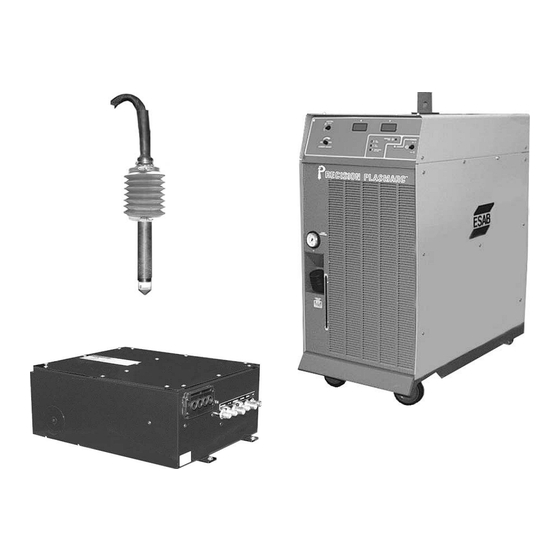
Precision plasmarc cutting and high speed marking system with integrated flow control
Hide thumbs
Also See for PT-24:
- Installation, operation and maintenance manual (220 pages) ,
- Instruction manual (128 pages) ,
- Installation, operation and maintenance manual (140 pages)
Table of Contents
Troubleshooting

Related Manuals for ESAB PT-24


Summary of Contents for ESAB PT-24
- Page 1 F-15-652 November, 2003 Installation, Operation and Maintenance Manual for the Precision PLASMARC Cutting and High Speed Marking SYSTEM with Integrated Flow Control 411 s. Ebenezer Road Florence, SC 29501-0545...
- Page 2 ESAB terms and conditions of sale for a specific statement of ESAB’s responsibilities and limitations on its liability. ESAB Cutting Systems first priority is total customer satisfaction. We constantly look for ways to improve our products, service and documentation.
-
Page 3: Table Of Contents
2.4.1 Precision Plasma System ............2 2.4.2 Plasma Gas ................3 2.4.3 Start Gas ................... 3 2.4.4 Secondary Gas ................3 2.4.5 Cut Gas ..................3 2.4.5 PT-24 Torch ................4 Section 3 Installation 3.1 General....................1 3.2 Equipment Required ................1 3.3 Location....................1 3.4 Primary Electrical Input Connections............ - Page 4 Precision Plasma Integrated Flow Control - CE Table of Contents Page Section 4 Operation 4.1 Power Supply Controls 4.1.1 Main Power Switch ..............1 4.1.2 Pilot Arc Switch ................1 4.1.3 Fault Indicator Lights..............2 4.1.4 Meters..................2 4.1.5 Current Control Switch..............2 4.2 Cut Quality ..................
- Page 5 5.3 PT-24 Torch Description ..............2-4 5.4 IFC Fluid Schematic ................3 5.4 Torch Maintenance ................5-6 5.5 PT-24 Consumable Disassembly and Inspection........7-10 5.6 PT-24 Torch Re-Assembly ..............10-11 5.7 Flow Control ..................12 5.8 Proportional Valve Removal ..............13 Section 6 Troubleshooting 6.1 General Safety ..................
- Page 6 7.5 Power Source Module ................ 18-25 7.6 IFC ..................... 26-27 7.7 IFC Manifold ..................28-29 7.8 PT-24 Torch Assembly IFC Series with Marking........30-31 7.9 Torch Manifold with marking ............... 32-33 7.10 Interface Cables and Hoses .............. 34-35 Customer/Technical Information...
-
Page 7: Section 1 Safety
The process of cutting metals with plasma equipment 1.1 Introduction provides industry with a valuable and versatile tool. ESAB cutting machines are designed to provide both operation safety and efficiency. However, as with any machine tool, sensible attention to operating procedures, precautions, and safe practices is necessary to achieve a full measure of usefulness. -
Page 8: Safety Notations And Symbols
SECTION 1 SAFETY The following words and symbols are used throughout 1.2 Safety Notations And Symbols this manual. They indicate different levels of required safety involvement. ALERT or ATTENTION. Your safety is involved or potential equipment failure exists. Used with other symbols and information. -
Page 9: General Safety Information
SECTION 1 SAFETY 1.3 General Safety Information Machine starts automatically. WARNING This equipment moves in various directions and speeds. · Moving machinery can crush. · Only qualified personnel should operate or service equipment. · Keep all personnel, materials, and equipment not involved in production process clear of entire system area. -
Page 10: Installation Precautions
Machine regulator is then used to obtain pressure required by torches. · Contact your ESAB representative before installation. He can suggest certain precautions regarding piping installation and machine lifting, etc. to ensure maximum security. ·... -
Page 11: Electrical Grounding
SECTION 1 SAFETY 1.5 Electrical Grounding Electrical grounding is imperative for proper machine operation and SAFETY. Refer to this manual’s Installation section for detailed grounding instructions. Electric shock hazard. WARNING Improper grounding can cause severe injury or death. Machine must be properly grounded before put into service. -
Page 12: Operating A Plasma Cutting Machine
SECTION 1 SAFETY 1.6 Operating A Plasma Cutting Machine Flying debris and loud noise hazards. WARNING · Hot spatter can burn and injure eyes. Wear goggles to protect eyes from burns and flying debris generated during operation. · Chipped slag may be hot and fly far. Bystanders should also wear goggles and safety glasses. - Page 13 SECTION 1 SAFETY Hazardous voltages. Electric shock WARNING can kill. · Do NOT touch plasma torch, cutting table or cable connections during plasma cutting process. · Always turn power off to plasma power supplies before touching or servicing plasma torch. ·...
- Page 14 SECTION 1 SAFETY Radiation hazard. WARNING Arc rays can injure eyes and burn skin. · Wear correct eye and body protection. · Wear dark safety glasses or goggles with side shields. Refer to following chart for recommended lens shades for plasma cutting: Arc Current Lens Shade Up to 100 Amps...
- Page 15 · Have fire extinguishing equipment available for use. CAUTION Poor Performance Will Result When Cutting Above Water. The PT-24 is designed to be a dry cutting process. Cutting above water may result in: · reduced consumable life ·...
- Page 16 SECTION 1 SAFETY Explosion hazard. WARNING · Certain molten aluminum-lithium (Al-Li) alloys can cause explosions when plasma cut OVER water. § These alloys should only be dry cut on a dry table. § DO NOT dry cut over water. § Contact your aluminum supplier for additional safety information regarding hazards associated with these alloys...
-
Page 17: Service Precautions
SECTION 1 SAFETY 1.7 Service Precautions Hazardous voltages. Electric shock WARNING can kill. · Do NOT touch plasma torch, cutting table or cable connections during plasma cutting process. · Always turn power off to plasma power supplies before touching or servicing plasma torch. ·... -
Page 18: Safety References
Systems for Welding and Cutting” - NFPA 51, National Fire Protection Association. · “Safety Precautions for Oxygen, Nitrogen, Argon, Helium, Carbon Dioxide, Hydrogen, and Acetylene,” Form 3499. ESAB Cutting Systems. Obtainable through your ESAB representative or local distributor. · "Design and Installation of Oxygen Piping Systems," Form 5110. - Page 19 SECTION 1 SAFETY International Accident Prevention VBG 1 General Provisions VBG 4 Electrical Equipment and operating Equipment VBG 15 Welding, Cutting and related working methods VBG 48 Shot Blasting Works VBG 61 Gases VBG 62 Oxygen VBG 87 Operating liquid jet cutting machines VBG 93 Laser beams, accident prevention and Electro-technology...
- Page 20 SECTION 1 SAFETY DIN Standards DIN 2310 Thermal cutting; terminology and Part 1 nomenclature DIN 2310 Thermal cutting; determination of quality of cut Part 2 faces DIN 2310 Thermal cutting; arc plasma cutting; process Part 4 principles, quality, dimensional tolerances DIN 2310 Thermal cutting;...
-
Page 21: Section 2 Description
Technical reference material is also provided to assist in troubleshooting the cutting package. 2.3 Package Options Available Precision Plasmarc® Integrated Flow Control package options available through your ESAB dealer Precision Plasmarc® Power Source (200/230/380/415/460/575) 3-phase 50/60 Hz (required) CNC Controllable/Without PLC... -
Page 22: Technical Specifications
Output Current Range 15-100 amps dc Output Load Voltage 120 V dc Duty Cycle 100% Open Circuit Voltage 315 V dc PT-24 Torch and Torch Bundle Power Supply CONTROL POWER CURRENT RECISION PLASMARC 44" (1118mm) 42" (1067mm) Integrated Flow Control 22"... -
Page 23: Plasma Gas
SECTION 2 DESCRIPTION 2.4.2 Plasma Gas Technical Specifications Type , Ar, Air Pressure 150 psig (10.4 bars) O , Air: 85 psig (5.9 bars) Ar Flow 100 cfh (47 l/min) max. (varies with application) -99.8 to 99.995% Purity Required* , Ar-99.995% Air-clean, dry and oil free Recommended Liquid Cylinder Oxygen: R-76-150-540LC (P/N 19777) -
Page 24: Pt-24 Torch
SECTION 2 DESCRIPTION 2.4.5 Pt-24 Torch Technical Specifications Type Water-Cooled, Dual Gas Rating 100 amps @ 100 % duty cycle Dimensions See Package Options (2.3) Precision Plasma with Integrated Flow Control -... -
Page 25: Section 3 Installation
SECTION 3 INSTALLATION 3.1 General Proper installation can contribute materially to the satisfactory and trouble-free operation of the NOTICE Precision Plasmarc® System. It is suggested that each step in this section be studied and carefully followed. 3.2 Equipment Required · Gas Supply and Hoses. -
Page 26: Primary Electrical Input Connections
SECTION 3 INSTALLATION 3.4 Primary Electrical Input Connections Electric Shock Can Kill! DANGER Provide maximum protection against electrical shock. Before any connections are made inside the machine, open the line (wall) disconnect switch and unplug the power cord. Input Power Configuration WARNING Machine must be properly configured for your input power. - Page 27 SECTION 3 INSTALLATION The following procedure explains the proper installation steps for connecting primary electrical power to the power source. 1. Remove right side panel. 2. Ensure input power cable is disconnected from all electrical sources. 3. Route input power cable through the strain relief Input Power Cable Ground Connection located at the rear panel.
-
Page 28: Alternate Connection Locations For
SECTION 3 INSTALLATION 3.5 Alternate Connection Locations For IFC I/O Strain Relief Alternate There are two locations for the I/O 24v input and for the torch. This provides flexibility while mounting the box to a machine. NOTE: When changing over alternate Torch connection location, be sure to replace hole... -
Page 29: Interconnecting Lines
SECTION 3 INSTALLATION 3.7 Interconnecting Lines Torch Bundle 1. All interconnecting service lines supplied are labeled or color coded on each end with Cooling water corresponding labels/colors marked on the return/Pilot cabinets. arc cable Gas lines Cooling Solenoid water to Cable torch 2. - Page 30 SECTION 3 INSTALLATION Power supply and IFC connections 3. Connect power and coolant lines in Power Supply Bundle from power source to IFC box. Power Supply Bundle Power bundle consists of #6 and # 7 coolant lines (with 5/8-18 L.H. fittings), power cable (#3 AWG) and yellow pilot arc cable (#16 AWG).
-
Page 31: Precision Plasmarc Component Interconnecting Diagram
SECTION 3 INSTALLATION 3.8 Precision Plasmarc® Component Interconnecting Diagram wall disconnect (cust. sup.) height control ASIOB enclosure primary power cable integrated flow control box precision plasma power source height control ASIOB cable*(see note) power bundle process ASIOB cable power supply I/O cable 15 120 vac/24vdc cable earth ground work cable (+) - Page 32 SECTION 3 INSTALLATION Gas Line Contamination Will CAUTION Damage Proportional Valves And Check Valves Purge Gas Lines Before connecting gas delivery lines to the Integrated Flow Control, purge all lines thoroughly. Residue from the hose manufacturing process may clog/damage the proportional valves in your flow control.
- Page 33 SECTION 3 INSTALLATION Gas connections and I/O Strain Relief 1/4 NPT 5. Connect gas delivery lines to integrated flow control. Install 25 micron gas filters in all delivery lines between gas source and IFC. 25 micron Gas Filter 25 µ Filters H-35 Proportional And Check Valves Are CAUTION...
- Page 34 SECTION 3 INSTALLATION Remove Access Cover Pilot Arc Work Torch 6. Remove panel from rear of console and attach the pilot-arc, torch and work lead. Power Source 7 Amp 500 Flow Control VAC Fuse Lead Rating Label 7. Connect power supply I/O cable between the console and the CNC.
-
Page 35: Torch Mounting
SECTION 3 INSTALLATION 3.9 Torch Mounting CAUTION Do Not Cover Vent Hole. When mounting, do not to cover the small vent hole in the side of the sleeve. This hole allows coolant to drain from inside the sleeve should a leak occur in a service line. -
Page 36: Torch Coolant
SECTION 3 INSTALLATION 3.10 Torch Coolant · Remove coolant fill cap at front of console and fill coolant tank with 4 gallons (15 liters) of plasma coolant, P/N 156F05 (one gallon). · Do not fill above maximum level Coolant · Fill Cap Reinstall Cap. -
Page 37: Using The 5 Solenoid Torch Manifold
7 to 10 second switching delay. The IFC is shipped configured to use the 5 solenoid torch manifold. Marking with the PT-24 torch and the IFC NOTICE does not utilize a proportional valve to regulate Argon pressure. An external regulator for the argon supply must be set to 85 PSI (5,6 bar). - Page 38 SECTION 3 INSTALLATION Procedure to modify IFC manifold for 4 solenoid torch manifold. View A-A A. Locate and remove access plug (1/8 NPT) next to the argon flow control solenoid as shown. To plasma From gas outlet plasma gas B. Remove port plug (1/16 NPT) from bottom of inlet access hole.
-
Page 39: Section 4 Operation
SECTION 4 OPERATION 4.1 Power Supply Controls 4.1.1 Main Power Switch Main Power Switch Controls the input power to the fan, water cooler and the PC Board. Amber indicator light to the left of the switch. EMERGENCY STOP 4.1.2 Pilot Arc Switch Pilot Arc Switch Previously a manual setting. -
Page 40: Fault Indicator Lights
SECTION 4 OPERATION 4.1.3 Fault Indicator Lights Fault Indicator Lights · Coolant flow will show low coolant flow. When unit is turned on, the light will briefly show a fault and then go out. · P/S Fault Indicator – fault in plasma control PCB in the inverter power source. -
Page 41: Current Control Switch
SECTION 4 OPERATION 4.1.5 Current Control Switch Control Remote/Panel Switch · Panel Position – Output current is set by the output current dial · Remote Position – output current is set by the CNC (or remote pot) with an analog dc signal 0-10 Vdc = 0-100 Adc ·... -
Page 42: Cut Quality
SECTION 4 OPERATION 4.2 Cut Quality 4.2.1 Introduction Causes affecting cut quality are interdependent. Changing one variable affects all others. Determining a solution may be difficult. The following guide offers possible solutions to different undesirable cutting results. To begin select the most prominent condition: §... -
Page 43: Cut Angle
SECTION 4 OPERATION 4.2.2 Cut Angle Negative Cut Angle Top dimension is greater than the bottom. · Part Misaligned torch · Bent or warped material · Worn or damaged consumables · Standoff low (arc voltage) · Cutting speed slow (machine travel rate) Part Drop Positive Cut Angle... -
Page 44: Cut Flatness
SECTION 4 OPERATION 4.2.3 Cut Flatness Top And Bottom Rounded Condition usually occurs when material is .25” thick (6,4mm) or less. · High current for given material thickness (See Process Data for proper settings). Drop Part Top Edge Undercut · Standoff low (Arc Voltage) Part Drop... -
Page 45: Surface Finish
SECTION 4 OPERATION 4.2.4 Surface Finish Process Induced Roughness Cut face is consistently rough. May or may not be confined to one axis. · Incorrect Shield Gas mixture (See Process Data) Top View · Worn or damaged consumables Cut Face Machine Induced Roughness Can be difficult to distinguish from Process Induced Roughness. -
Page 46: Dross
SECTION 4 OPERATION 4.2.5 Dross Dross is a by-product of the cutting process. It is the undesirable material that remains attached to the part. In most cases, dross can be reduced or eliminated with proper torch and cutting parameter setup. Refer to Cut Face Process Data. - Page 47 SECTION 4 OPERATION Side View Splatter Top Dross Appears as splatter on top of material. Usually removes easily. · Cutting speed fast · Standoff high (arc voltage). Cut Face Intermittent Dross Appears on top or bottom along kerf. Non-continuous. Can appear as any kind of dross ·...
-
Page 48: Dimensional Accuracy
SECTION 4 OPERATION 4.2.6 Dimensional Accuracy Generally using the slowest possible speed (within approved levels) will optimize part accuracy. Select consumables to allow a lower arc voltage and slower cutting speed. Recommended cutting speed and arc voltage will NOTICE give optimal cutting performance in most cases. Small incremental adjustments may be needed due to material quality, material temperature and specific alloy. -
Page 49: Influence Of Gas Options On Cut Quality
SECTION 4 OPERATION 4.3 Influence of Gas Options on Cut Quality 4.3.1 Introduction All gases are not suitable for all situations. Certain gases assist in cutting specific materials and thickness. The following explains why certain gases are selected and their influence on the finished part. Other influences such as arc voltage and gas flow/pressure are covered in the Process Data. - Page 50 SECTION 4 OPERATION Refer to Cutting Process Data in the PT24 NOTICE Manual for recommended flow/pressure settings. 4.3.3 Carbon Steel Material Thickness: 26 GA (.018") to 10 GA (.135") (0,5 mm to 3,4 mm) · Smooth cut face Cut Qualities: ·...
- Page 51 SECTION 4 OPERATION Refer to Cutting Process Data in the PT24 NOTICE Manual for recommended flow/pressure settings. 4.3.4 Stainless Steel Material Thickness: 22 GA (.028") to 16 GA (.062") (0,7 mm to 1,6 mm) · Positive cut angle · Cut Qualities: Excellent dross performance ·...
- Page 52 SECTION 4 OPERATION Refer to Cutting Process Data for NOTICE recommended flow/pressure settings. Stainless Steel Material Thickness: .125" to .625" (3,2 mm to 15,9 mm) · Matted cut edge appearance · Light gray color Cut Qualities: · Much smoother finish ·...
-
Page 53: Process Data 4.4.1 Introduction
The following information is a result of many hours of testing and is a general guide for setting up and cutting with a PT-24 Precision Plasmarc® System. In most cases these settings will provide a quality cut. The data contains values for: ·... - Page 54 Shield Gas: Nitrogen (N ) @ 150 psi / 10.4 bar ® Shield Mix Gas: Methane (CH ) @ 100 psi / 6.9 bar PT-24 Torch with Integrated Flow Control Torch Body P/N 21758 Water Baffle P/N 21725 O-Ring P/N 638797...
-
Page 55: Aluminum
SECTION 4 OPERATION Process Data 15 Initial / 30 Final Amperes Precision Plasma Integrated Flow Control Aluminum Plasma Gas Shield Gas 1 Shield Gas 2 Material Thickness In. 0.062 0.075 0.09 0.125 0.187 0.250 Timers Pierce Delay (sec.) Initial to Final Current (sec.) Setup Parameters 93.1 93.1... - Page 56 Shield Gas: Nitrogen (N ) @ 150 psi / 10.4 bar ® Shield Mix Gas: Methane (CH ) @ 100 psi / 6.9 bar PT-24 Torch with Integrated Flow Control Torch Body P/N 21758 Water Baffle P/N 21725 O-Ring P/N 638797...
-
Page 57: Aluminum
SECTION 4 OPERATION Process Data 28 Initial – 55 Final Amperes Precision Plasma Integrated Flow Control Aluminum Plasma Gas Shield Gas 1 Shield Gas 2 Material Thickness In. 0.062 0.125 0.125 0.250 Timers Pierce Delay (sec.) Initial to Final Current (sec.) Setup Parameters Plasma Start Gas 1- psi/bar... - Page 58 Shield Gas: Nitrogen (N ) @ 150 psi / 10.4 bar ® Shield Mix Gas: Methane (CH ) @ 100 psi / 6.9 bar PT-24 Torch with Integrated Flow Control Torch Body P/N 21758 Water Baffle P/N 21725 O-Ring P/N 638797...
- Page 59 SECTION 4 OPERATION Process Data 35 Initial / 70 Final Amperes Precision Plasma Integrated Flow Control Aluminum Plasma Gas Shield Gas 1 Shield Gas 2 Material Thickness In. 0.187 0.250 0.375 0.500 12,7 Timers Pierce Delay (sec.) Initial to Final Current (sec.) Setup Parameters 76.6 76.6...
- Page 60 Shield Gas: Nitrogen (N ) @ 150 psi / 10.4 bar ® Shield Mix Gas: Methane (CH ) @ 100 psi / 6.9 bar PT-24 Torch with Integrated Flow Control Torch Body P/N 21758 Water Baffle P/N 21725 O-Ring P/N 638797...
- Page 61 SECTION 4 OPERATION Process Data 50 Initial / 100 Final Amperes Precision Plasma Integrated Flow Control Aluminum Plasma Gas Shield Gas 1 Shield Gas 2 Material Thickness In. 0.250 0.375 0.500 0.625 12,7 15,9 Timers Pierce Delay (sec.) Initial to Final Current (sec.) Setup Parameters 76.4 76.4...
- Page 62 Shield Gas: Nitrogen (N ) @ 150 psi / 10.4 bar ® Shield Mix Gas: Oxygen (O ) @ 150 psi / 10.4 bar PT-24 Torch with Integrated Flow Control Torch Body P/N 21758 Water Baffle P/N 21725 O-Ring P/N 638797...
- Page 63 SECTION 4 OPERATION Process Data 16 Initial / 16 Final Amperes Precision Plasma Integrated Flow Control Carbon Steel Plasma Gas Shield Gas 1 Shield Gas 2 Material Thickness In. 20Ga 18Ga 16Ga 14Ga 12Ga 10Ga Timers Pierce Delay (sec.) Initial to Final Current (sec.) Setup Parameters 71.3 71.3...
- Page 64 Shield Gas: Nitrogen (N ) @ 150 psi / 10.4 bar ® Shield Mix Gas: Oxygen (O ) @ 150 psi / 10.4 bar PT-24 Torch with Integrated Flow Control Torch Body P/N 21758 Water Baffle P/N 21725 O-Ring P/N 638797...
-
Page 65: Carbon Steel
SECTION 4 OPERATION Process Data 18 Initial / 35 Final Amperes Precision Plasma Integrated Flow Control Carbon Steel Plasma Gas Shield Gas 1 Shield Gas 2 Material Thickness In. 14Ga 0.125 0.135 0.187 0.250 Timers Pierce Delay (sec.) Initial to Final Current (sec.) Setup Parameters 86.9 86.9... - Page 66 Shield Gas: Nitrogen (N ) @ 150 psi / 10.4 bar ® Shield Mix Gas: Oxygen (O ) @ 150 psi / 10.4 bar PT-24 Torch with Integrated Flow Control Torch Body P/N 21758 Water Baffle P/N 21725 O-Ring P/N 638797...
- Page 67 SECTION 4 OPERATION Process Data 23 Initial / 45 Final Amperes Precision Plasma Integrated Flow Control Carbon Steel Plasma Gas Shield Gas 1 Shield Gas 2 Material Thickness In. 0.125 0.135 0.187 0.250 0.375 Timers Pierce Delay (sec.) Initial to Final Current (sec.) Setup Parameters 73.8 73.8...
- Page 68 Shield Gas: Nitrogen (N ) @ 150 psi / 10.4 bar ® Shield Mix Gas: Oxygen (O ) @ 150 psi / 10.4 bar PT-24 Torch with Integrated Flow Control Torch Body P/N 21758 Water Baffle P/N 21725 O-Ring P/N 638797...
- Page 69 SECTION 4 OPERATION Process Data 35 Initial / 70 Final Amperes Precision Plasma Integrated Flow Control Carbon Steel Plasma Gas Shield Gas 1 Shield Gas 2 Material Thickness In. 0.187 0.250 0.312 0.375 0.500 0.625 12,7 15,9 Timers Pierce Delay (sec.) Initial to Final Current (sec.) Setup Parameters 66.7...
- Page 70 Shield Gas: Nitrogen (N ) @ 150 psi / 10.4 bar ® Shield Mix Gas: Oxygen (O ) @ 150 psi / 10.4 bar PT-24 Torch with Integrated Flow Control Torch Body P/N 21758 Water Baffle P/N 21725 O-Ring P/N 638797...
- Page 71 SECTION 4 OPERATION Process Data 50 Initial / 100 Final Amperes Precision Plasma Integrated Flow Control Carbon Steel Plasma Gas Shield Gas 1 Shield Gas 2 Material Thickness In. 0.312 0.375 0.500 0.625 0.750 12,9 15,9 19,1 Timers Pierce Delay (sec.) Initial to Final Current (sec.) Setup Parameters 77.5...
- Page 72 Shield Gas: Nitrogen (N ) @ 150 psi / 10.4 bar ® Shield Mix Gas: Oxygen (O ) @ 150 psi / 10.4 bar PT-24 Torch with Integrated Flow Control Torch Body P/N 21758 Water Baffle P/N 21725 O-Ring P/N 638797...
- Page 73 SECTION 4 OPERATION Process Data 15 Initial / 30 Final Amperes Precision Plasma Integrated Flow Control Stainless Steel Plasma Gas Shield Gas 1 Shield Gas 2 Material Thickness In. 26Ga 24Ga 22Ga 18Ga 16Ga Timers Pierce Delay (sec.) Initial to Final Current (sec.) Setup Parameters 99.8 99.8...
- Page 74 Final Amperes: 50 Plasma Gas: Air @ 150 psi / 10.4 bar Shield Gas: Air @ 150 psi / 10.4 bar ® Shield Mix Gas: PT-24 Torch with Integrated Flow Control Torch Body P/N 21758 Water Baffle P/N 21725 O-Ring...
-
Page 75: Stainless Steel
SECTION 4 OPERATION Process Data 25 Intial / 50 Final Amperes Precision Plasma Integrated Flow Control Stainless Steel Plasma Gas Shield Gas 1 Shield Gas 2 Material Thickness In. 0.125 0.187 0.250 0.375 Timers Pierce Delay (sec.) Initial to Final Current (sec.) Setup Parameters Plasma Start Gas 1- psi/bar... - Page 76 Final Amperes: 70 Plasma Gas: Air @ 150 psi / 10.4 bar Shield Gas: Air @ 150 psi / 10.4 bar ® Shield Mix Gas: PT-24 Torch with Integrated Flow Control Torch Body P/N 21758 Water Baffle P/N 21725 O-Ring...
- Page 77 SECTION 4 OPERATION Process Data 35 Initial / 70 Final Amperes Precision Plasma Integrated Flow Control Stainless Steel Plasma Gas Shield Gas 1 Shield Gas 2 Material Thickness In. 0.187 0.250 0.375 0.500 12,7 Timers Pierce Delay (sec.) Initial to Final Current (sec.) Setup Parameters 79.1 79.1...
- Page 78 Final Amperes: 100 Plasma Gas: Air @ 150 psi / 10.4 bar Shield Gas: Air @ 150 psi / 10.4 bar ® Shield Mix Gas: PT-24 Torch with Integrated Flow Control Torch Body P/N 21758 Water Baffle P/N 21725 O-Ring...
- Page 79 SECTION 4 OPERATION Process Data 50 Initial / 100 Final Amperes Precision Plasma Integrated Flow Control Stainless Steel Plasma Gas Shield Gas 1 Shield Gas 2 Material Thickness In. 0.250 0.375 0.500 0.625 12,7 15,9 Timers Pierce Delay (sec.) Initial to Final Current (sec.) Setup Parameters 79.1 79.1...
- Page 80 Air @ 150 psi / 10.4 bar Shield Gas: Air @ 150 psi / 10.4 bar ® Shield Mix Gas: Methane (CH ) @ 100 psi / 6.9 bar PT-24 Torch with Integrated Flow Control Torch Body P/N 21758 Water Baffle P/N 21725 O-Ring...
- Page 81 SECTION 4 OPERATION Process Data 35 Initial / 70 Final Amperes Precision Plasma Integrated Flow Control Stainless Steel Plasma Gas Shield Gas 1 Shield Gas 2 Material Thickness In. 0.125 0.187 0.250 0.375 0.500 12,7 Timers Pierce Delay (sec.) Initial to Final Current (sec.) Setup Parameters 80.5 80.5...
- Page 82 Air @ 150 psi / 10.4 bar Shield Gas: Air @ 150 psi / 10.4 bar ® Shield Mix Gas: Methane (CH ) @ 100 psi / 6.9 bar PT-24 Torch with Integrated Flow Control Torch Body P/N 21758 Water Baffle P/N 21725 O-Ring...
- Page 83 SECTION 4 OPERATION Process Data 50 Initial / 100 Final Amperes Precision Plasma Integrated Flow Control Stainless Steel Plasma Gas Shield Gas 1 Shield Gas 2 Material Thickness In. 0.250 0.375 0.500 0.625 12,7 15,9 Timers Pierce Delay (sec.) Initial to Final Current (sec.) Setup Parameters 78.6 78.6...
- Page 84 Nitrogen (N ) @ 150 psi / 10.4 bar Shield Gas: Nitrogen (N ) @ 150 psi / 10.4 bar ® Shield Mix Gas: PT-24 Torch with Integrated Flow Control Torch Body P/N 21758 Water Baffle P/N 21725 O-Ring P/N 638797...
- Page 85 SECTION 4 OPERATION Process Data 25 Intial / 50 Final Amperes Precision Plasma Integrated Flow Control Stainless Steel Plasma Gas Shield Gas 1 Shield Gas 2 Material Thickness In. 0.125 0.187 0.250 0.375 Timers Pierce Delay (sec.) Initial to Final Current (sec.) Setup Parameters 78.5 78.5...
- Page 86 Nitrogen (N ) @ 150 psi / 10.4 bar Shield Gas: Nitrogen (N ) @ 150 psi / 10.4 bar ® Shield Mix Gas: PT-24 Torch with Integrated Flow Control Torch Body P/N 21758 Water Baffle P/N 21725 O-Ring P/N 638797...
- Page 87 SECTION 4 OPERATION Process Data 35 Initial / 70 Final Amperes Precision Plasma Integrated Flow Control Stainless Steel Plasma Gas Shield Gas 1 Shield Gas 2 Material Thickness In. 0.187 0.250 0.375 0.500 12,7 Timers Pierce Delay (sec.) Initial to Final Current (sec.) Setup Parameters 81.1 81.1...
- Page 88 Nitrogen (N ) @ 150 psi / 10.4 bar Shield Gas: Nitrogen (N ) @ 150 psi / 10.4 bar ® Shield Mix Gas: PT-24 Torch with Integrated Flow Control Torch Body P/N 21758 Water Baffle P/N 21725 O-Ring P/N 638797...
- Page 89 SECTION 4 OPERATION Process Data 50 Initial / 100 Final Amperes Precision Plasma Integrated Flow Control Stainless Steel Plasma Gas Shield Gas 1 Shield Gas 2 Material Thickness In. 0.250 0.375 0.500 0.625 12,7 15,9 Timers Pierce Delay (sec.) Initial to Final Current (sec.) Setup Parameters 79.1 79.1...
- Page 90 Shield Gas: Nitrogen (N ) @ 150 psi / 10.4 bar ® Shield Mix Gas: Methane (CH ) @ 100 psi / 6.9 bar PT-24 Torch with Integrated Flow Control Torch Body P/N 21758 Water Baffle P/N 21725 O-Ring P/N 638797...
- Page 91 SECTION 4 OPERATION Process Data 25 Initial / 50 Final Amperes* Precision Plasma Integrated Flow Control Stainless Steel Plasma Gas Shield Gas 1 Shield Gas 2 Material Thickness In. 22Ga 20Ga 18Ga 16Ga Timers Pierce Delay (sec.) Initial to Final Current (sec.) Setup Parameters 78.5 78.5...
- Page 92 Shield Gas: Nitrogen (N ) @ 150 psi / 10.4 bar ® Shield Mix Gas: Methane (CH ) @ 100 psi / 6.9 bar PT-24 Torch with Integrated Flow Control Torch Body P/N 21758 Water Baffle P/N 21725 O-Ring P/N 638797...
- Page 93 SECTION 4 OPERATION Process Data 35 Initial / 70 Final Amperes Precision Plasma Integrated Flow Control Stainless Steel Plasma Gas Shield Gas 1 Shield Gas 2 Material Thickness In. 0.187 0.250 0.375 0.500 12,7 Timers Pierce Delay (sec.) Initial to Final Current (sec.) Setup Parameters 79.6 79.6...
- Page 94 Shield Gas: Nitrogen (N ) @ 150 psi / 10.4 bar ® Shield Mix Gas: Methane (CH ) @ 100 psi / 6.9 bar PT-24 Torch with Integrated Flow Control Torch Body P/N 21758 Water Baffle P/N 21725 O-Ring P/N 638797...
- Page 95 SECTION 4 OPERATION Process Data 50 Initial / 100 Final Amperes Precision Plasma Integrated Flow Control Stainless Steel Plasma Gas Shield Gas 1 Shield Gas 2 Material Thickness In. 0.250 0.312 0.375 0.500 0.625 12,7 15,9 Timers Pierce Delay (sec.) Initial to Final Current (sec.) Setup Parameters 79.6...
-
Page 96: Aluminum Kerf Values
SECTION 4 OPERATION 4.4.3.1 Aluminum Kerf Values N Aluminum N 30 Amperes Material Thickness (mm) 1.575 1.905 2.286 3.175 4.750 6.350 0.140 3.556 0.120 3.048 0.100 2.540 2.210 0.080 2.032 0.087 1.651 1.524 0.060 1.524 0.065 1.270 1.270 1.270 0.060 0.050 0.050 0.050... - Page 97 SECTION 4 OPERATION Aluminum N 70 Amperes Material Thickness (mm) 4.750 6.350 9.525 12.700 0.190 4.826 0.170 4.318 0.150 3.810 0.130 3.302 3.048 2.845 0.120 0.110 2.794 2.540 2.540 0.112 0.100 0.100 0.090 2.286 0.070 1.778 0.050 1.270 0.187 0.250 0.375 0.500 Material Thickness (inches)
-
Page 98: Carbon Steel Kerf Values
SECTION 4 OPERATION 4.4.3.2 Carbon Steel Kerf Values O Carbon Steel O 16 Amperes Material Thickness (mm) 1.219 3.404 0.140 3.556 0.120 3.048 0.100 2.540 0.080 2.032 1.473 0.060 1.524 1.118 0.058 0.040 1.016 0.044 0.020 0.508 0.000 0.000 0.048 0.134 Material Thickness (inches) Carbon Steel O... - Page 99 SECTION 4 OPERATION Carbon Steel O 45 Amperes Material Thickness (mm) 3.175 6.350 9.525 0.140 3.556 0.120 3.048 2.413 0.100 2.540 0.095 1.930 0.080 2.032 1.626 0.076 0.060 1.524 0.064 0.040 1.016 0.020 0.508 0.000 0.000 0.125 0.250 0.375 Material Thickness (inches) Carbon Steel O 70 Amperes Material Thickness (mm)
- Page 100 SECTION 4 OPERATION Carbon Steel O 100 Amperes Material Thickness (mm) 9.525 12.700 19.050 0.140 3.556 3.048 0.120 3.048 0.120 2.540 0.100 2.337 2.540 0.100 0.092 0.080 2.032 0.060 1.524 0.040 1.016 0.020 0.508 0.000 0.000 0.375 0.500 0.750 Material Thickness (inches) 4-60 Precision Plasma with Integrated Flow Control - CE...
-
Page 101: Stainless Steel Kerf Values O
SECTION 4 OPERATION 4.4.3.3 Stainless Steel Kerf Values O Stainless Steel O 30 Amperes Material Thickness (mm) 0.457 0.584 0.726 1.207 1.588 0.140 3.556 0.120 3.048 0.100 2.540 0.080 2.032 0.060 1.524 1.143 0.889 0.889 0.889 0.889 0.040 1.016 0.045 0.035 0.035 0.035... -
Page 102: Stainless Steel Kerf Values Air/Air/Ch
SECTION 4 OPERATION 4.4.3.4 Stainless Steel Kerf Values Air/Air/CH Stainless Steel Air/Air/CH 70 Amperes Material Thickness (mm) 3.175 4.775 6.350 9.525 12.700 0.140 3.556 2.921 0.120 3.048 0.115 2.540 0.100 2.540 2.286 0.100 2.032 0.090 0.080 2.032 1.778 0.080 0.070 0.060 1.524 0.040... -
Page 103: Stainless Steel Kerf Values N
SECTION 4 OPERATION 4.4.3.5 Stainless Steel Kerf Values N Stainless Steel N 70 Amperes Material Thickness (mm) 4.750 6.350 9.525 12.700 0.140 3.556 2.921 0.120 3.048 2.667 0.115 2.413 0.100 2.540 0.105 0.095 2.032 0.080 2.032 0.080 0.060 1.524 0.040 1.016 0.020 0.508... - Page 104 SECTION 4 OPERATION 4.4.3.6 Stainless Steel Kerf Values N Stainless Steel N 50 Amperes Material Thickness (mm) 3.175 4.750 6.350 9.525 0.140 3.556 0.120 3.048 0.100 2.540 2.032 0.080 2.032 1.778 0.080 1.651 1.524 0.070 0.060 1.524 0.065 0.060 0.040 1.016 0.020 0.508...
- Page 105 SECTION 4 OPERATION Stainless Steel N 100 Amperes Material Thickness (mm) 6.350 9.525 12.700 15.875 0.190 4.826 0.170 4.318 0.150 3.810 3.556 0.140 0.130 3.302 3.048 2.794 0.120 0.110 2.794 2.540 0.110 0.100 0.090 2.286 0.070 1.778 0.050 1.270 0.250 0.375 0.500 0.625...
-
Page 106: Stainless Steel Kerf Values Air/Air
SECTION 4 OPERATION 4.4.3.7 Stainless Steel Kerf Values Air/Air Stainless Steel Air/Air 50 Amperes Material Thickness (mm) 3.175 4.750 6.350 9.525 0.140 3.556 0.120 3.048 2.413 0.100 2.540 2.032 0.095 0.080 2.032 0.080 1.651 1.524 0.060 1.524 0.065 0.060 0.040 1.016 0.020 0.508... - Page 107 SECTION 4 OPERATION Stainless Steel Air/Air 100 Amperes Material Thickness (mm) 6.350 9.525 12.700 15.875 0.190 4.826 0.170 4.318 4.064 0.160 0.150 3.810 3.556 3.302 0.140 0.130 3.302 2.921 0.130 0.110 2.794 0.115 0.090 2.286 0.070 1.778 0.050 1.270 0.250 0.375 0.500 0.625...
- Page 108 Material: Carbon and Stainless Steel Amperes: 10 Plasma Gas: Argon, Ar @ 150 PSI / 10.4 Bar Shield Gas: Air @ 150 PSI / 10.4 Bar PT-24 Torch with Integrated Flow Control Torch Body P/N 21758 Water Baffle P/N 21725 O-Ring...
- Page 109 SECTION 4 OPERATION Plasma Marking Process Data 10 Amperes Precision Plasma Integrated Flow Control Carbon and Stainless Steel Plasma Gas Shield Gas 1 Material Thickness ALL Thickness Timers Pierce Delay (sec.) Setup Parameters Plasma Start Gas 1- psi 83.2/5.6 bar Plasma Cut Gas 1- psi 83.2/5.6 bar 132/9.0 bar...
- Page 110 Material: Carbon and Stainless Steel Amperes: 15 Plasma Gas: Argon, Ar @ 150 PSI / 10.4 Bar Shield Gas: Air @ 150 PSI / 10.4 Bar PT-24 Torch with Integrated Flow Control Torch Body P/N 21758 Water Baffle P/N 21725 O-Ring...
- Page 111 SECTION 4 OPERATION Plasma Marking Process Data 15 Amperes Precision Plasma Integrated Flow Control Carbon and Stainless Steel Plasma Gas Shield Gas 1 Material Thickness ALL Thickness Timers Pierce Delay (sec.) Setup Parameters Plasma Start Gas 1- psi 83.2/5.6 bar Plasma Cut Gas 1- psi 83.2/5.6 bar 132/9.0 bar...
- Page 112 Material: Carbon and Stainless Steel Amperes: 10 Plasma Gas: Argon, Ar @ 150 PSI / 10.4 Bar Shield Gas: Air @ 150 PSI / 10.4 Bar PT-24 Torch with Integrated Flow Control Torch Body P/N 21758 Water Baffle P/N 21725 O-Ring...
- Page 113 SECTION 4 OPERATION Plasma Marking Process Data 10 Amperes Precision Plasma Integrated Flow Control Carbon and Stainless Steel Plasma Gas Shield Gas 1 Material Thickness ALL Thickness Timers Pierce Delay (sec.) Setup Parameters Plasma Start Gas 1- psi 83.2/5.6 bar Plasma Cut Gas 1- psi 83.2/5.6 bar 132/9.0 bar...
- Page 114 Material: Carbon and Stainless Steel Amperes: 15 Plasma Gas: Argon, Ar @ 150 PSI / 10.4 Bar Shield Gas: Air @ 150 PSI / 10.4 Bar PT-24 Torch with Integrated Flow Control Torch Body P/N 21758 Water Baffle P/N 21725 O-Ring...
- Page 115 SECTION 4 OPERATION Plasma Marking Process Data 15 Amperes Precision Plasma Integrated Flow Control Carbon and Stainless Steel Plasma Gas Shield Gas 1 Material Thickness ALL Thickness Timers Pierce Delay (sec.) Setup Parameters Plasma Start Gas 1- psi 83.2/5.6 bar Plasma Cut Gas 1- psi 83.2/5.6 bar 132/9.0 bar...
- Page 116 Material: Carbon and Stainless Steel Amperes: 15 Plasma Gas: Argon, Ar @ 150 PSI / 10.4 Bar Shield Gas: Air @ 150 PSI / 10.4 Bar PT-24 Torch with Integrated Flow Control Torch Body P/N 21758 Water Baffle P/N 21725 O-Ring...
- Page 117 SECTION 4 OPERATION Plasma Marking Process Data 15 Amperes Precision Plasma Integrated Flow Control Carbon and Stainless Steel Plasma Gas Shield Gas 1 Material Thickness ALL Thickness Timers Pierce Delay (sec.) Setup Parameters Plasma Start Gas 1- psi 83.2/5.6 bar Plasma Cut Gas 1- psi 83.2/5.6 bar 132/9.0 bar...
- Page 118 Material: Carbon and Stainless Steel Amperes: 10 Plasma Gas: Argon, Ar @ 150 PSI / 10.4 Bar Shield Gas: Air @ 150 PSI / 10.4 Bar PT-24 Torch with Integrated Flow Control Torch Body P/N 21758 Water Baffle P/N 21725 O-Ring...
- Page 119 SECTION 4 OPERATION Plasma Marking Process Data 10 Amperes Precision Plasma Integrated Flow Control Carbon and Stainless Steel Plasma Gas Shield Gas 1 Material Thickness ALL Thickness Timers Pierce Delay (sec.) Setup Parameters Plasma Start Gas 1- psi 83.2/5.6 bar Plasma Cut Gas 1- psi 83.2/5.6 bar 132/9.0 bar...
- Page 120 Material: Carbon and Stainless Steel Amperes: 20 Plasma Gas: Argon, Ar @ 150 PSI / 10.4 Bar Shield Gas: Air @ 150 PSI / 10.4 Bar PT-24 Torch with Integrated Flow Control Torch Body P/N 21758 Water Baffle P/N 21725 O-Ring...
- Page 121 SECTION 4 OPERATION Plasma Marking Process Data 20 Amperes Precision Plasma Integrated Flow Control Carbon and Stainless Steel Plasma Gas Shield Gas 1 Material Thickness ALL Thickness Timers Pierce Delay (sec.) Setup Parameters Plasma Start Gas 1- psi 83.2/5.6 bar Plasma Cut Gas 1- psi 83.2/5.6 bar 132/9.0 bar...
- Page 122 Material: Carbon and Stainless Steel Amperes: 30 Plasma Gas: Argon, Ar @ 150 PSI / 10.4 Bar Shield Gas: Air @ 150 PSI / 10.4 Bar PT-24 Torch with Integrated Flow Control Torch Body P/N 21758 Water Baffle P/N 21725 O-Ring...
- Page 123 SECTION 4 OPERATION Plasma Marking Process Data 30 Amperes Precision Plasma Integrated Flow Control Carbon and Stainless Steel Plasma Gas Shield Gas 1 Material Thickness ALL Thickness Timers Pierce Delay (sec.) Setup Parameters Plasma Start Gas 1- psi 83.2/5.6 bar Plasma Cut Gas 1- psi 83.2/5.6 bar 132/9.0 bar...
- Page 124 Material: Carbon and Stainless Steel Amperes: 10 Plasma Gas: Argon, Ar @ 150 PSI / 10.4 Bar Shield Gas: Air @ 150 PSI / 10.4 Bar PT-24 Torch with Integrated Flow Control Torch Body P/N 21758 Water Baffle P/N 21725 O-Ring...
- Page 125 SECTION 4 OPERATION Plasma Marking Process Data 10 Amperes Precision Plasma Integrated Flow Control Carbon and Stainless Steel Plasma Gas Shield Gas 1 Material Thickness ALL Thickness Timers Pierce Delay (sec.) Setup Parameters Plasma Start Gas 1- psi 83.2/5.6 bar Plasma Cut Gas 1- psi 83.2/5.6 bar 132/9.0 bar...
- Page 126 Material: Carbon and Stainless Steel Amperes: 30 Plasma Gas: Argon, Ar @ 150 PSI / 10.4 Bar Shield Gas: Air @ 150 PSI / 10.4 Bar PT-24 Torch with Integrated Flow Control Torch Body P/N 21758 Water Baffle P/N 21725 O-Ring...
- Page 127 SECTION 4 OPERATION Plasma Marking Process Data 30 Amperes Precision Plasma Integrated Flow Control Carbon and Stainless Steel Plasma Gas Shield Gas 1 Material Thickness ALL Thickness Timers Pierce Delay (sec.) Setup Parameters Plasma Start Gas 1- psi 83.2/5.6 bar Plasma Cut Gas 1- psi 83.2/5.6 bar 132/9.0 bar...
- Page 128 Material: Carbon and Stainless Steel Amperes: 30 Plasma Gas: Argon, Ar @ 150 PSI / 10.4 Bar Shield Gas: Air @ 150 PSI / 10.4 Bar PT-24 Torch with Integrated Flow Control Torch Body P/N 21758 Water Baffle P/N 21725 O-Ring...
- Page 129 SECTION 4 OPERATION Plasma Marking Process Data 30 Amperes Precision Plasma Integrated Flow Control Carbon and Stainless Steel Plasma Gas Shield Gas 1 Material Thickness ALL Thickness Timers Pierce Delay (sec.) Setup Parameters Plasma Start Gas 1- psi 83.2/5.6 bar Plasma Cut Gas 1- psi 83.2/5.6 bar 132/9.0 bar...
- Page 130 SECTION 4 OPERATION This page intentionally left blank. 4-90 Precision Plasma with Integrated Flow Control -...
-
Page 131: Section 5 Maintenance
SECTION 5 MAINTENANCE 5.1 General If this equipment does not operate properly, stop work immediately and investigate the cause. Qualified personnel must perform maintenance work. Do NOT permit untrained persons to inspect, clean or repair equipment. Use only recommended replacement parts. Electric Shock Can Kill! WARNING Before attempting any inspection or repair inside... -
Page 132: Pt-24 Torch Description
· Occasionally, bleed all water from the filter below the air filter-regulator. 5.3 Pt-24 Torch Description 2.0" (51 mm) 1.812" (46 mm) Diameter Sleeve Diameter Collar ·... -
Page 133: Ifc Fluid Schematic
SECTION 5 MAINTENANCE Check Valve IFC Fluid Schematic Proportional Valve · Pressure Switch Plasma Cut and Start Gas. These gases enter the torch through connections that house check valves within the torch body. The valves acting in 2 Way Solenoid Valve conjunction with solenoid valves control the back and forth switching of start and cut gases. - Page 134 SECTION 5 MAINTENANCE · Shield Gas. Shield preflow, cut shield and postflow enter the torch through one connection. These gases pass through: § the torch body, § the shield gas diffuser, § out the orifice in the shield cap surrounding the plasma jet.
-
Page 135: Torch Maintenance
SECTION 5 MAINTENANCE 5.4 Torch Maintenance Electric Shock Can Kill WARNING Before performing torch maintenance: · Turn power switch on the console to the OFF position. · Disconnect primary input power. Torch Body O-Rings · Each day before starting operation, check O-rings on the torch body. - Page 136 SECTION 5 MAINTENANCE Sleeve Torch Sleeve P/N 22568 · The torch sleeve P/N 22568 is threaded onto the torch body. · If the sleeve is too tight for hand removal, use a large adjustable wrench on the body flats or lightly tighten these flats in a vise.
-
Page 137: Consumable Disassembly And Inspection
SECTION 5 MAINTENANCE 5.5 PT-24 Consumable Disassembly And Inspection Hot Torch Will Burn! WARNING · Allow torch to cool before servicing. · Torch is water cooled, but may be hot immediately after use. Electric Shock Can Kill! WARNING · Turn power switch on the console OFF. - Page 138 Notice that a small amount of coolant is lost each time consumables are removed. This is normal and the coolant will eventually have to be PT-24 Front End replaced. Check coolant before each operation. 1. Unscrew the cup shield/retainer. Inspect around orifice for damage.
- Page 139 SECTION 5 MAINTENANCE 4. Unscrew the nozzle retainer/diffuser. Inspect for damage, especially where the retainer contacts the nozzle. The surface between the retainer and Nozzle nozzle create a metal to metal seal for the coolant. Any damage to this sealing surface will cause a leak resulting in poor cutting.
- Page 140 SECTION 5 MAINTENANCE 6. Remove the swirl baffle from the nozzle. If the baffle remains in the torch, it will come free when removing the electrode. Check the small gas passages of the swirl baffle for blockage and clear blockages with an air stream. If blockages cannot be cleared, replace baffle.
-
Page 141: Torch Re-Assembly
SECTION 5 MAINTENANCE 5.6 PT-24 Torch Tip Re-assembly 1. Electrode Apply a thin film of silicone grease to the O-ring, just enough to produce a shiny surface. Thread electrode in place and tighten snugly with tool provided. DO NOT OVER TIGHTEN. - Page 142 SECTION 5 MAINTENANCE 4. Shield Cup Insulator Push the shield cup insulator on the nozzle retainer. This component is a press fit and may remain assembled when the assembly was taken apart. Shield Cup Insulator Nozzle Retainer 5. Insulator Shield Retainer Apply a thin coat of silicone grease to the O-ring and thread insulator shield retainer on to Shield Cup.
-
Page 143: Flow Control
SECTION 5 MAINTENANCE 5.7 Flow Control Nitrogen Is Vented Inside Integrated NOTICE Flow Control Box. A small amount of nitrogen gas is vented internally to provide cooling, safety, and a slight positive pressure. Chamber Vent To prevent continuous building of pressure, the flow control chamber is externally vented. -
Page 144: Proportional Valve Removal
SECTION 5 MAINTENANCE 5.8 Proportional Valve Removal Proportional Valves can be removed if replacement is required, without disassembling the manifold from the IFC box. 1. Access the outside bottom of the unit by unbolting the IFC box from the machine. 2. -
Page 145: Section 6 Troubleshooting
SECTION 6 TROUBLESHOOTING 6.1 General Safety Electric Shock Can Kill! WARNING Externally disconnect all primary power to the machine before servicing. Open the line (wall) disconnect switch or circuit breaker before attempting inspection or work inside the power source. High Voltages Can Be Stored In WARNING Capacitors. -
Page 146: Troubleshooting Guide
SECTION 6 TROUBLESHOOTING 6.2 Troubleshooting Guide 6.2.1 Reduced Consumable Life Cutting Up Skeletons Cutting skeletons (discarded material left after all pieces have been removed from a plate) to facilitate their removal from the table can adversely affect electrode life by: ·... -
Page 147: Poor Cut Quality
SECTION 6 TROUBLESHOOTING See Cut Quality In Section 4 6.2.2 Poor Cut Quality 6.2.3 No Pilot Arc Bad (shorted) Pilot Arc Cable Replace Cable Contaminated Electrode Clean or replace electrode Insufficient spark gap setting Set spark gap to 0.040” in plumbing box. Pilot Arc Contactor (PAC) Replace contactor malfunctioning... -
Page 148: Nozzle Life Extremely Short
SECTION 6 TROUBLESHOOTING 6.2.7 Nozzle Life Extremely Short Pilot Arc H/L switch Refer to Process Data in wrong position Nozzle arcing inside bore Gas quality below purity specification Start gas flow too low Check Process Data cutting parameters 6.2.8 Short Electrode Life Insufficient cooling Check pump for 150 psi output pressure Start gas quality Gas quality below purity specification Cut gas quality Gas quality below purity specification... -
Page 149: Ifc Fluid Schematic
SECTION 6 TROUBLESHOOTING 6.3 IFC Fluid Schematic and Manifold Valve Identification Schematic Legend ARGON Check Valve AIR 2 AIR 1 Proportional Valve O2-2 O2-1 N2-3 N2-1 N2-2 Pressure Switch 50 psi rising H-35 Solenoid Valve H-35 METHANE SHIELD GAS 2 OUT PLASMA GAS 2 OUT SHIELD GAS 1 OUT PLASMA GAS 1 OUT... -
Page 150: Ifc Electrical Schematic
SECTION 6 TROUBLESHOOTING 6.4 IFC Electrical Schematic Part 1 Next Page PLASMA 2 PLASMA 1 ESAB ASIOB SYSTEM SHIELD 1 SHIELD 2 X35-1 WHITE COMMON SION X35-2 SION GREEN GNDE X35-3 GNDE BLACK VCCE X35-4 VCCE SHIELD GROUND X35-5 GROUND... -
Page 151: Ifc Electrical Schematic
SECTION 6 TROUBLESHOOTING Part 2 IFC Electrical Schematic Previous page P4-1 PLASMA GAS 1 PRESSURE P4-2 P4-3 PLASMA GAS 2 PRESSURE P4-4 P4-5 SHIELD GAS 1 PRESSURE P4-6 P4-7 SHIELD GAS 2 Proportional Valves PRESSURE P4-8 LCD Meter PLASMA GAS 1 9-BAR PROPORTIONAL VALVE V1 Output For 1 +24 VDC... -
Page 152: Precision Plasma Power Source Electrical Schematic
SECTION 6 TROUBLESHOOTING 6.5 Precision Plasma Power Source Electrical Schematic Part 1 180VAC 120 VAC 120 VAC P2 J2 NEUTRAL NEUTRAL COOLANT PUMP PCB1 P10-5 18VAC ISOLATION AMPLIFIER AND P10-3 18VAC P10-4 FAULT SIGNAL PCB P2-10 38103 18VAC P2-9 18VAC P2-8 LED1 LED4... - Page 153 SECTION 6 TROUBLESHOOTING Part 2 Component Legend zone item description zone item description Transformer control, plasma interface Terminal brd Terminal strip MOV1,2,3 Mov 610V Terminal strip Auto transformer Recepacle 10 pos Receptacle 19 pos Plug 10 pos Potentiometer 10K Receptacle 16 pos Zener diode 180v Plug 16 pos K2,3...
-
Page 154: Precision Plasma Power Source Wiring Diagram (Includes Ce Version)
SECTION 6 TROUBLESHOOTING 6.6 Precision Plasma Power Source Wiring Diagram - CE Part 1 Note: PLC1 (connection) refers to an area located on an enclosure that housed the former Programmable Logic Controller. This plasma power supply is CNC (cutting machine) controlled and does not use a PLC. PCB1 P4-10(VIO) P4-11(GRY) - Page 155 SECTION 6 TROUBLESHOOTING Wiring Diagram – Precision Plasma Power Source -CE Part 2 Note: PLC1 (connection) refers to an area located on an enclosure that housed the former Programmable Logic Controller. This plasma power supply is CNC (cutting machine) controlled and does not use a PLC. LINE LOAD BR1-A T2-AH2...
- Page 156 SECTION 6 TROUBLESHOOTING Wiring Diagram – Precision Plasma Power Source -CE Part 3 Note: PLC1 (connection) refers to an area located on an enclosure that housed the former Programmable Logic Controller. This plasma power supply is CNC (cutting machine) controlled and does not use a PLC. MOD1 CB1-2(GRY) M1-1(BLK)
- Page 157 SECTION 6 TROUBLESHOOTING Wiring Diagram – Precision Plasma Power Source - CE Part 4 Note: PLC1 (connection) refers to an area located on an enclosure that housed the former Programmable Logic Controller. This plasma power supply is CNC (cutting machine) controlled and does not use a PLC. PCB2-PA(YEL) PLC1 MODULE PCB2...
- Page 158 SECTION 6 TROUBLESHOOTING Wiring Diagram – Precision Plasma Power Source - CE Part 5 MOD1 PCB1 P4-3(RED) PCB1 P4-3 (RED) R10-1 (GRY) PCB1 P4-4(YEL) PCB1 P4-4 (YEL) TB5-WORK(BLK) PCB1 P4-15(BLU) PCB1 P4-15 (BLU) PCB1 P4-16(ORN) PCB1 P4-16 (ORN) PCB1 P1-13 (BLK) TB6-6 (BRN) PCB1 P1-14 (RED)) TB6-8 (GRY)
-
Page 159: Power Module Schematic - Ce Version
SECTION 6 TROUBLESHOOTING 6.7 Power Module Schematic - CE Version 6-15 Precision Plasma with Integrated Flow Control -CE... - Page 160 SECTION 6 TROUBLESHOOTING 6.8 Power Module Wiring Diagram – CE Version PAGE 1 6-16 Precision Plasma with Integrated Flow Control -CE...
- Page 161 SECTION 6 TROUBLESHOOTING Power Module Wiring – CE Version PAGE 2 6-17 Precision Plasma with Integrated Flow Control -CE...
-
Page 162: Torch Manifold
SECTION 6 TROUBLESHOOTING 6.9 Torch Manifold Plasma 2 Plasma 1 Shield 2 Shield 1 Wire Shield 1 & Shield 2 Common Numbers Plasma 1 & Plasma 2 Common Argon Common Argon 6-18 Precision Plasma with Integrated Flow Control -CE... -
Page 163: Section 7 Replacement Parts
7.2 Ordering To ensure proper operation, it is recommended that only genuine ESAB parts and products be used with this equipment. The use of non-ESAB parts may void your warranty. Replacement parts may be ordered from your... -
Page 164: Plasmarc Power Source-Exterior Components
SECTION 7 REPLACEMENT PARTS 7.3 Plasmarc Power Source-Exterior Components Precision Plasma with Integrated Flow Control... - Page 165 SECTION 7 REPLACEMENT PARTS Item Part Number Elec. Symbol Description Number 35925YL Cover-Top 995227 Label Warning-Exposed High Volt 2091514 Label Warning 35924YL Panel, Side 61328087 Screw, HMH ¼-20 X .50 L 13734588 Logo ESAB Clear Precision Plasma with Integrated Flow Control...
- Page 166 SECTION 7 REPLACEMENT PARTS "TEE" Detail Page 7-12 Precision Plasma with Integrated Flow Control...
- Page 167 SECTION 7 REPLACEMENT PARTS Item Part Number Symbol Description Number (Elec-Ay) 672508 Switch Toggle 2PST 2 Pos 15A 951061 AM1,VM1 Meter LED 5VDC 954928 Overlay, Control Panel CNC 951061 AM1,VM1 Meter LED 5VDC 634518 S2,3 Switch Toggle DPDT 2 Pos 15A 2062018 Pot LIN 10.0K 2.00W 0.63L 1 turn 32286GY...
- Page 168 SECTION 7 REPLACEMENT PARTS Precision Plasma with Integrated Flow Control...
- Page 169 SECTION 7 REPLACEMENT PARTS Item Part Number Symbol Description Number (Elec-Ay) 35928GY Door Access Rear 952209 Conn Box Recpt 19 FS SH 97W63 3 Strain Relief 23610197 Plug Hole .875 Dia. .125 CT Nyl BK 950874 Circuit Breaker 7 AMP 952137 Fuse 7A 500 VAC Fast Acting 32202GY...
-
Page 170: Plasmarc Power Source-Internal Components
SECTION 7 REPLACEMENT PARTS 7.4 Plasmarc Power Source-Internal Components Precision Plasma with Integrated Flow Control... - Page 171 SECTION 7 REPLACEMENT PARTS Item Part Number Symbol Description Number (Elec-Ay) 35920GY Base, Precision Plasma 950487 Term Block 2 pos 9639533 Bushing, Snap .88 I.D. X 1.09 MH X .45 L 38103 PCB1 PCB Isolation AMP 950096 PCB1 P9,7 Housing Contact, Crimp 3 pin 952053 Standoff #6-32 X .88 L 952034...
- Page 172 SECTION 7 REPLACEMENT PARTS 7-10 Precision Plasma with Integrated Flow Control...
- Page 173 SECTION 7 REPLACEMENT PARTS Item Part Number Symbol Description Number (Elec-Ay) 952026 Terminal Block 673502 Contactor 3 Pole 75A 672002GY Shroud, Fan 2062334 Motor, Fan 36417GY Shroud, Fan 951215 Motor, Carb 1/3 Hp 951347 Pump, Carb w/Strainer 13735308 Relay Enclose DPDT 120VAC 20A 0558002158 Kit, Wire Primary 33550...
- Page 174 SECTION 7 REPLACEMENT PARTS 44" Long 16 X5 “TEE” Detail 7-12 Precision Plasma with Integrated Flow Control...
- Page 175 SECTION 7 REPLACEMENT PARTS Item Part Number Symbol Description Number (Elec-Ay) 36538 Hose, Assy Pump Outlet- Torch out 950001 Switch, Flow .25 GPM SPSTB 21124 Valve, Check Assy 36539 Hose, Assy Flowswitch To Core 90858009 TBG, Nylobrade 3/8 I.D X .625 O.D. 36418 Hose Assy Tank Bottom- Pump Inlet 36423...
- Page 176 SECTION 7 REPLACEMENT PARTS 7-14 Precision Plasma with Integrated Flow Control...
- Page 177 SECTION 7 REPLACEMENT PARTS Item Part Number Symbol Description Number (Elec-Ay) 13735961 Heat Exchanger 950823 Bushing, Snap 950167 Grommet, Rub 1.12 I.D. X 1.50 O.D. X .06 W 995103 Terminal Block 24 POS 15A 35919 Board, Terminal Output 2017483 Holder, Fuse 92W57 Grommet, Rub .63 I.D.
- Page 178 SECTION 7 REPLACEMENT PARTS 7-16 Precision Plasma with Integrated Flow Control...
- Page 179 SECTION 7 REPLACEMENT PARTS Item Part Number Symbol Description Number (Elec-Ay) 950823 Bushing, Snap 17750020 R11,12 Res 20 ohm 50W 36527GY Cover, Terminal Board 951161 C1,2 Cap, Metpoly 20uf 400VDC 673458 K2,3 Contactor, Pilot Arc 3P 40A 2234521 P4,MOD1 Plug, 16 Pos P1,PLC1 P2 2234877 PLC1 J1...
- Page 180 SECTION 7 REPLACEMENT PARTS 7.5 Power Source Power Module 7-18 Precision Plasma with Integrated Flow Control...
- Page 181 SECTION 7 REPLACEMENT PARTS Item Part Number Symbol Description Number (Elec-Ay) 35914GY Base Power Module 37102 Bracket, PCB KYDEX 35918 Wire Kit, Power Module 951339 PCB1 P1, 5 Plug, Female 12 Position 951340 PCB1 P2, 6 Plug, Female 14 Position 37101GY Deck, Power Module 951981...
- Page 182 SECTION 7 REPLACEMENT PARTS CE only CE only Section A-A 7-20 Precision Plasma with Integrated Flow Control...
- Page 183 SECTION 7 REPLACEMENT PARTS Item Part Number Symbol Description Number (Elec-Ay) 2234877 J3,4 Block Terminal 10 Position 951182 Fan, Axial 950487 Terminal Strip 2 Position 950823 Bushing, Snap 35700 Inductor, Power Factor 17280215 Resistor 1.5K OHM 100W 35680 Inductor Assembly Output 35681 Transformer Assembly, Main 952160...
- Page 184 SECTION 7 REPLACEMENT PARTS 7-22 Precision Plasma with Integrated Flow Control...
- Page 185 SECTION 7 REPLACEMENT PARTS Item Part Number Symbol Description Number (Elec-Ay) 2234518 Block Terminal, 8 Position 38047 Shunt, Feedback 2234519 Block Terminal, 16 Position 35917GY Baffle Heatsink 951981 Heatsink 2234877 J3, 4 Block Terminal, 10 Position 674156 Adaptor 7-23 Precision Plasma with Integrated Flow Control...
- Page 186 SECTION 7 REPLACEMENT PARTS CE units only CE units only 7-24 Precision Plasma with Integrated Flow Control...
- Page 187 SECTION 7 REPLACEMENT PARTS Item Part Number Symbol Description Number (Elec-Ay) 35940 Transformer Control 951978 Bridge Diode 3PH 130A 952611 Bridge Diode 3 PH 951192 Pad Thermal Bridge 951833 Pad Termal IGBT 1200V 35794 Busbar Input Bridge 951979 SCR1 SCR 90A 951196 Pad Thermal SCR Module 951980...
- Page 188 SECTION 7 REPLACEMENT PARTS 7.6 Precision Plasma Flow Control Unit Replacement Parts 7-26 Precision Plasma with Integrated Flow Control...
-
Page 189: Ifc Manifold
SECTION 7 REPLACEMENT PARTS Item Part Number Symbol Description Number (Elec-Ay) See Detail IFC Manifold Assembly 37401 Electrode, Spark Gap, .188” Dia.w/SolderLug 674969 PCB Special Function Filter 56996230 ASIOB Relay Output Card 2237927 ASIOB Analog Output Card 2237924 ASIOB Control System Motherboard 7-27 Precision Plasma with Integrated Flow Control... - Page 190 SECTION 7 REPLACEMENT PARTS 7.7 IFC Flow Control Manifold Assembly - Detail Bottom View- Manifold PS2 Red PS1 Red PS3 Black PS1 Black PS4 Black PS2 Black PS3 Red PS4 Red 7-28 Precision Plasma with Integrated Flow Control...
- Page 191 SECTION 7 REPLACEMENT PARTS Item Part Number Quantity Description Number 0558002074 Manifold Assembly without Proportional Valves 952921 Valve, Solenoid 2-way, Man Mt. O2. S2 24/60 1/8 Or. 10Z30 Pipe Ftg Brass, Adptr ¼ MNPT X Male 5/8 –11 Hose 74S76 Pipe Ftg Brass, Adptr ¼...
- Page 192 SECTION 7 REPLACEMENT PARTS 7.8 PT-24 Torch Assembly IFC Series P/N 0558002396 Shield 1 IN Orange Shield 1 OUT Orange Shield 2 IN Black Plasma 2 IN Yellow Plasma 2 OUT Yellow Argon IN Red Plasma 1 OUT Blue Plasma 1 IN Blue .284"...
- Page 193 SECTION 7 REPLACEMENT PARTS Item Part Number Symbol Description Number (Elec-Ay) 21758 Body & Tube Assembly PT-24 Torch 22568 Sleeve, Torch PT-24 22381 Gas Line Start Blue 22380 Gas Line Cut Yellow 22382 Gas Line Shield Orange/Red See Process Data...
- Page 194 SECTION 7 REPLACEMENT PARTS 7.9 Torch Ar Gas Manifold PT24 IFC Plasma 2 Plasma 1 Shield 2 Shield 1 Shield 1 & Shield 2 Common Plasma 1 & Plasma 2 Common Argon Common Argon 7-32 Precision Plasma with Integrated Flow Control...
- Page 195 SECTION 7 REPLACEMENT PARTS Item Part Number Symbol Description Number (Elec-Ay) 0558001502 Flange 952921 2 Way Solenoid Valves 593985 O-Ring 7-33 Precision Plasma with Integrated Flow Control...
- Page 196 SECTION 7 REPLACEMENT PARTS 7.10 PT-24 IFC Interface Cables 7-34 Precision Plasma with Integrated Flow Control...
- Page 197 SECTION 7 REPLACEMENT PARTS Item Part Number Description Number Reference Gas Supply Lines Reference Main Power Cable Reference 120 VAC/24 VDC Cable Reference Process ASIOB Cable Reference Height Control ASIOB Cable (comes from a junction with process ASIOB cable inside the flow control 22428 12 ft.
- Page 198 SECTION 7 REPLACEMENT PARTS 7-36 Precision Plasma with Integrated Flow Control...
- Page 199 See back of Title Page for revision list.
- Page 200 Customer // Technical Support (843) 664-4405 (800) ESAB-123 (372-2123) ESAB Welding and Cutting Products PO BOX 100545 Ebenezer Road Florence, SC 29501-0545 http://www.esab.com ESAB Cutting Systems – Canada 6010 Tomken Road Mississauga, Ontario Canada L5T 1X9 Phone: (905) 670-0220 Fax: (905) 670-4879...
Need help?
Do you have a question about the PT-24 and is the answer not in the manual?
Questions and answers