Table of Contents
Advertisement
Instruction Manual
Form 5086
November 1998
Type 128-PQC Control Valves
Contents
. . . . . . . . . . . . . . . . . . . . . . . . . . . . . . .
. . . . . . . . . . . . . . . . . . . . . . . . . . . . .
. . . . . . . . . . . . . . . . . . . . . . . . . . . . . . . . . .
. . . . . . . . . . . . . . . . . . . . . . . . . . . . . . .
. . . . . . . . . . . . . . . . . . . . . . . . . . . . . . . .
. . . . . . . . . . . . . . . . . . . . . . . . . . . . . .
. . . . . . . . . . . . . . . . . . . . . . . . . . . .
Parts Kits
. . . . . . . . . . . . . . . . . . . . . . . . . . . . . . . . .
. . . . . . . . . . . . . . . . . . . . . . . . . . . . . . . . . .
Introduction
Scope of Manual
This manual provides installation, maintenance, and
parts information for the Type 128-PQC control valve.
Instructions and parts lists for Fisher Controls pneu-
matic instrumentation and other equipment used with
this control valve are found in separate manuals.
Only personnel qualified through training or experience
should install, operate, or maintain the Type 128-PQC
control valve. If you have any questions concerning
the instructions in this manual, please contact your
Fisher Controls sales office or sales representative
before proceeding.
1
1
1
1
3
. . . . . . . . . . . . . . . . . . .
4
4
. . . . . . . . . . . . . . . . . . .
5
. . . . . . . . . . . . . . . . . .
6
. . . .
6
7
7
8
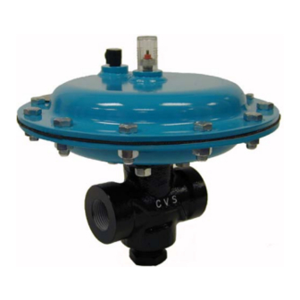
ALTERNATE LOCATION
OF PIPE PLUG FOR USE
AS ANGLE VALVE
W2838-2*/IL
Figure 1. Type 128-PQC Control Valve
Description
The Type 128-PQC control valve provides on-off
dump valve service for such oil production applications
as separators, scrubbers, and treaters, even under
sour gas conditions. It also may be used in general
on-off high-pressure control of a wide variety of liquids
and gases, including those which are sticky or gritty
and erosive. The Type 128-PQC valve is a 1-inch
combination control valve with a pipe plug in the bot-
tom connection for straight-through globe valve flow as
shown in figure 1. However, the pipe plug may be
field-changed to the left-hand end connection as
shown in figure 3 for angle flow.
Specifications
Table 1 lists specifications for the Type 128-PQC con-
trol valve. Some of the specifications for a given con-
trol valve as it originally comes from the factory are
stamped on a nameplate, shown in figure 2, located
on the upper diaphragm casing flange.
128-PQC
LOCATION OF PIPE PLUG
FOR USE AS GLOBE VALVE
Advertisement
Table of Contents

Related Manuals for Fisher 128-PQC


Summary of Contents for Fisher 128-PQC
-
Page 1: Table Of Contents
Introduction and gases, including those which are sticky or gritty and erosive. The Type 128-PQC valve is a 1-inch combination control valve with a pipe plug in the bot- Scope of Manual... - Page 2 128-PQC Table 1. Specifications Available Configurations Material Temperature Capabilities Metal Seat: –20 to 180 F (–29 to 82 C) Type 128 Actuator: Yokeless, on-off spring-and-di- aphragm actuator with action field-reversible be- Soft Seat: –20 to 150 F (–29 to 66 C) tween LCC Valve Body: –50 to 180 F (–46 to 82 C)
-
Page 3: Installation
128-PQC Table 3. Maximum Allowable Shutoff Pressure Drops CADMIUM COLORED MAIN RED MAIN SPRING 14A9077X012 SPRING 14A8831X012 PORT PORT FLOWING FLOWING DIAMETER 0 to 20 Psig (0 or 0 to 35 Psig (0 or 0 to 20 Psig (0 or... -
Page 4: Principle Of Operation
CAGE AND SEAT VALVE PLUG W5750-1*/IL Figure 3. Type 128-PQC Control Valve with Spring-Close Action 3. Make sure that the valve is oriented so that flow is A leakoff vent passes through the packing box and out in the desired direction. If angle flow is desired, switch the valve body. -
Page 5: Replacing Packing And Trim
Because of the care Fisher Controls takes in meeting all manufacturing requirements (heat treating, dimen- sional tolerances, etc.), use only replacement parts manufactured or furnished by Fisher Controls. -
Page 6: Changing Main Spring Range
128-PQC pressed against them. Then, push the packing spring figure 9) and remove the stem nut and thrust washer washer (key 6), packing spring (key 7), other packing (keys 49 and 51 in figure 9). spring washer, wiper ring, and packing box washer 2. -
Page 7: Parts Ordering
Parts Ordering shoulder of the nut and the plug end of the stem is The Type 128-PQC control valve is assigned a serial equal to dimension A in figure 6. number which can be found on the nameplate. A typi- 9. -
Page 8: Parts List
128-PQC 10B7899-C/DOC Figure 5. Replacement Packing and Trim Assemblies for Metal-Seated Construction Description Part Number Description Part Number 3A* Valve Plug Parts List Metal Seat, 1/4 & 3/8 inch ports 440C stainless steel, heat treated 16A2087X012 Travel Indicator Assembly 35A1588X0A2... - Page 9 128-PQC Description Part Number DIMENSION A Packing Box Washer, stainless steel Inches 1/2 inch and smaller ports 14A6617X012 Spring-Close Spring-Open Spring-Close Spring-Open 3/4 inch port 14A8807X012 Assembly Assembly Assembly Assembly 2.46 2.72 62.5 69.1 Washer, stainless steel (2 req’d) 14A8808X012...
- Page 10 128-PQC 20B7894-A/DOC Figure 7. Design PQC Valve Body Assembly Replacement Packing and Trim Assembly Part Numbers PORT PORT TFE V-RING PACKING, HEAT-TREATED TFE V-RING PACKING, HEAT-TREATED TFE V-RING PACKING, NITRONIC 50 TFE V-RING PACKING, NITRONIC 50 DIAMETER 440C STAINLESS STEEL VALVE PLUG AND CAGE...
- Page 11 128-PQC 29A0341-A/DOC 29A0343-A/DOC Figure 8. Type 128 Actuator...
- Page 12 36A1772-A/DOC Figure 9. Optional Handjack Assembly Fisher, Fisher-Rosemount, and Managing The Process Better are marks owned by Fisher Controls International, Inc. or Fisher-Rosemount Systems, Inc. All other marks are the property of their respective owners. Fisher Controls International, Inc. 1988, 1998; All Rights Reserved...
Need help?
Do you have a question about the 128-PQC and is the answer not in the manual?
Questions and answers