Advertisement
Quick Links
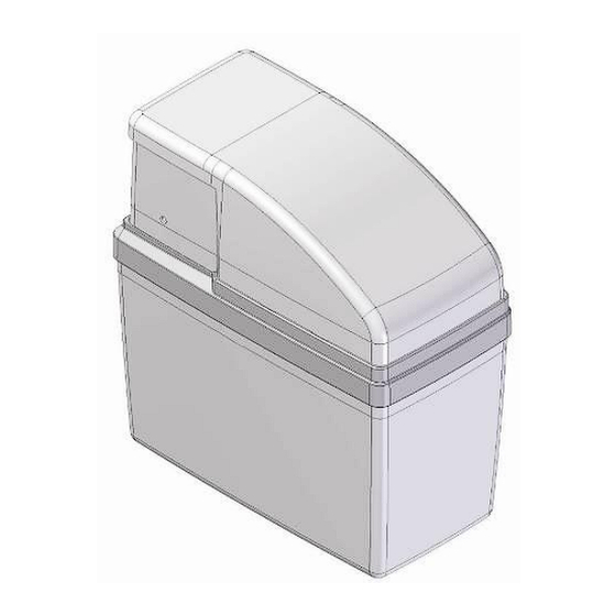
1. Parts:
1. BYPASS
2. VALVE HOUSING
3. RESIN TANK
CONTAINER FOR
4.
DEVICE AND SALT
BRINE VALVE
5.
(floater)
6. WATER INLET
DELTA WATER ENGINEERING
I
N
S
T
A
L
L
A
T
I
O
I
N
S
T
A
L
L
A
T
I
O
E
S
C
A
L
E
S
C
A
L
7. WATER OUTLET
8. BLENDING REGULATOR
9. HARDNESS REGULATOR
10. TO BRINE VALVE
11. CONNECTIONS (1/2", 3/4", 1")
12. TO DRAIN
N
G
U
I
D
E
N
G
U
I
D
E
D
A
D
A
V05/2009/P1
Advertisement

Related Manuals for Delta ESCALDA

Summary of Contents for Delta ESCALDA
- Page 1 7. WATER OUTLET 2. VALVE HOUSING 8. BLENDING REGULATOR 3. RESIN TANK 9. HARDNESS REGULATOR CONTAINER FOR 10. TO BRINE VALVE DEVICE AND SALT BRINE VALVE (floater) 11. CONNECTIONS (1/2", 3/4”, 1") 6. WATER INLET 12. TO DRAIN DELTA WATER ENGINEERING V05/2009/P1...
-
Page 2: Installation
Check incoming pressure: minimum 1 bar (dynamic), maximum 8 bar (static) (15 PSI- 116 PSI). If necessary reduce incoming pressure. Do not install the Delta Softener close to a heating source (environment temperature must be below 50°C). Protect softener and drain (12) against frost. - Page 3 (min. temp. 5°C, max. temp. 50°C). elbow outlet with straight outlet maximum height and distance of flexible drain hose CAUTION: For the installation of the flexible drain hose to the fixed piping, please follow local legislation. DELTA WATER ENGINEERING V05/2009/P3...
- Page 4 Once the hole has been drilled, mount the overflow tap and secure it with the supplied nut. After drilling, remove all bits of plastic that have fallen into the salt bin. A separate instruction leaflet with detailed information has been added to the device. DELTA WATER ENGINEERING V05/2009/P4...
- Page 5 The device can be installed in the container in three different ways: at the back, to the left or to the right. The support at the bottom of the container must be placed accordingly. Please refer to the figures on the following page. DELTA WATER ENGINEERING V05/2009/P5...
- Page 6 The arrow on the support in the container must be pointing to the back. Place the device in the container with the connections at the back, as shown below. 3.4.2 Connections to the left: As in 3.4.1. DELTA WATER ENGINEERING V05/2009/P6...
- Page 7 = part number 8 on the illustration on page 1 With the blending regulator, you determine outgoing hardness. Depending desired residual hardness, set outgoing hardness with a hex key number setting proportional, i.e. 1/10 – 1/5 – 1/… of total incoming hardness. DELTA WATER ENGINEERING V05/2009/P7...
- Page 8 5.3. Add water in the salt bin until the water level is approx. 10cm (4”) high. (the floater on the brine valve must be afloat) 5.4. Turn the bypass slowly to “service” mode. Open the main valve when you do not use a Bypass. DELTA WATER ENGINEERING V05/2009/P8...
- Page 9 Open a tap behind the softener for several minutes to allow residual water to be flushed from the tubing. 5.6.4. Check outgoing hardness with a “hardness test kit” (not supplied by Delta). Adjust blending if necessary. DELTA WATER ENGINEERING V05/2009/P9...
- Page 10 Then place the front lid. For future salt refills, only the front lid has to be removed. Don’t forget to connect the overflow to the drain. DELTA WATER ENGINEERING V05/2009/P10...
- Page 11 REMARKS: It is recommended that a water softener is installed by a professional. Although the DELTA softener is probably the easiest and safest softener on the market, it is imperative that necessary precautions are taken local legislation is followed. This installation guide is written to help the professional installer keeping in mind that this person has essential knowledge about hydraulic softeners and domestic plumbing.
Need help?
Do you have a question about the ESCALDA and is the answer not in the manual?
Questions and answers