JUKI ACF-172-1790 Engineer's Manual
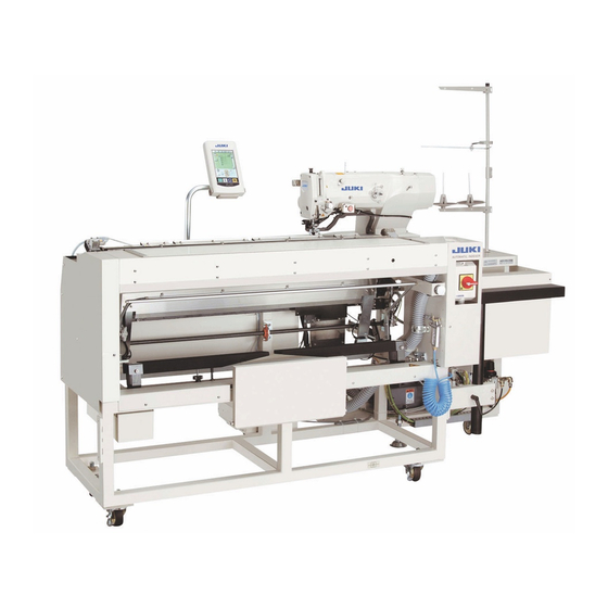
1-needle, lockstitch
automatic buttonholing machine
Hide thumbs
Also See for ACF-172-1790:
- Instruction manual (40 pages) ,
- Instruction manual (142 pages) ,
- Operation instruction (2 pages)
Table of Contents
Advertisement
Quick Links
Download this manual
See also:
Instruction Manual
Advertisement
Table of Contents

Related Manuals for JUKI ACF-172-1790


Summary of Contents for JUKI ACF-172-1790
- Page 1 1-Needle, Lockstitch Automatic buttonholing Machine ACF-172-1790 ENGINEER’S MANUAL 40018329 No.E360-00...
- Page 2 PREFACE This Engineer’s Manual is written for the technical personnel who are responsible for the service and maintenance of the machine. The Instruction Manual for these machines intended for the maintenance personnel and operators at an apparel factory contains operating instructions in detail. And this manual describes “Standard Adjustment”, “Adjustment Procedures”, “Results of Improper Adjustment”, and other important information which are not covered by the Instruction Manual.
-
Page 3: Table Of Contents
CONTENTS 1. GENERAL ....................1 (1) Features ........................1 (2) Configuration of the main parts ................2 2. SPECIFICATIONS ..................3 3. ADJUSTMENT OF EACH MAIN COMPONENT ........4 (1) Adjustment of the pneumatic components ............4 1) Adjusting the air blower ........................4 2) Adjusting the air blower for the needle bar .................. - Page 4 9. ELECTRICAL COMPONENTS ..............68 (1) Initialization of the data ..................68 (2) Adaptation to the high voltage ................68 (3) DIP switches......................68 (4) Fuse list ......................... 69 10. MAINTENANCE AND INSPECTION ............70 (1) Air layout diagram ....................70 (2) Sensor layout diagram ..................
-
Page 5: General
1. GENERAL Mainly consisting of a sewing machine, preset board, carriage, stacker, the ACF-172-1790 indexer is designed to automatically carry out a series of operations starting sewing button on the front top-center strips of men’s shirts, etc. and ending with stacking of workpieces. -
Page 6: Configuration Of The Main Parts
(2) Configuration of the main parts 1 Sewing machine head 7 Knee switch !3 Cloth palate 2 Preset board 8 Pause switch !4 Handle of the cloth plate 3 Carriage 9 Hand switch !5 Tool box 4 Stacker !0 Workpiece detector switch !6 Thread stand 5 Control panel !1 Air gun... -
Page 7: Specifications
T/C broadcloth, wool (with top-center plait, 2-fold, 3-fold, 2-piece superimposed that can be sewn feed) Lubricating oil Hook lubrication : JUKI New Defrix Oil No. 1 (equivalent to ISO VG7) Not necessary when using dry-hook Pitch 0.2 to 2.5 mm Applicable garment Width A : 220 to 420 mm (8.7 to 16.5") -
Page 8: Adjustment Of Each Main Component
3. ADJUSTMENT OF EACH MAIN COMPONENT (1) Adjustment of the pneumatic components Standard Adjustment 1) Adjusting the air blower − 4 −... - Page 9 Adjustment Procedures Results of Improper Adjustment 1. The air blower is provided with four blow pipes as illustrated in the figure on the left. The arrows of full line show the air blowing direction of the respective pipes. The name and function of each components are as follows : Blower for the carriage 1 To be used for bellowing...
-
Page 10: Adjusting The Air Blower For The Needle Bar
Standard Adjustment 2) Adjusting the air blower for the needle bar 9.5 ± 0.5mm 3) Vacuum adjusting metal fittings 4) Sensor to detect the number of garment bodies stacked − 6 −... - Page 11 Adjustment Procedures Results of Improper Adjustment 1. When dust collected on the needle bar area falls and is caught in the seams, adjust the direction and strength of the air blower.The air blower blows dust away and prevents dust from falling under needle.
-
Page 12: Adjusting The Carriage Lamp
(2) Adjusting the carriage lamp Standard Adjustment 1) Adjusting the position of the clamps Adjust the position of the clamp only when you wish to eliminate a clearance between the clamps or you wish change the arrangement of the clamp. 2) Adjusting the clamping force When adjusting the position of the clamps or replacing the clamp cushion 6, perform the adjustment below. - Page 13 Adjustment Procedures Results of Improper Adjustment 1. If you wish to eliminate a clearance between the clamps, loosen screws 3 either in clamps (small) 1 or in clamp (large) 2, and move the relevant one. Then tighten screws 3. 2. If you wish to change the arrangement of clamp (small) 1 and clamp (large) 2, remove screws 3, and re-position the clamps as you wish.
-
Page 14: Adjusting The Stacking Board Of The Stacker
(3) Adjusting the stacking board of the stacker Standard Adjustment 1. If sewing garment bodies with pockets, adjust the stacking board following the steps, adjust the stacking board following the steps described below. This adjustment allows the stacker to stack approximately 140 pieces of garment bodies with pockets ( material : T/C board cloth ). - Page 15 Adjustment Procedures Results of Improper Adjustment 1. When sewing men’s wear, loosen locknuts 2 in the reverse side of staking board 1 on the right side, and raise the stacking board until the reverse side of the stacking board 1 is flush with the reverse side of the locknut 2.
-
Page 16: Error Code List
4. ERROR CODE LIST Error code Display Description How to recover Place of recovery Contact of initialization of EEP-ROM of MAIN CONTROL p.c.b. E001 Turn OFF the power. When data is not written in EEP-ROM or data is broken, initialization of the data is automatically informed. - Page 17 Error code Display Description How to recover Place of recovery Enlargement error E043 Possible to re-start after Data input screen Sewing pitch exceeds 5 mm. pressing reset key. Stop switch E050 Possible to re-start after Step screen When stop switch is pressed during machine running. pressing reset key.
- Page 18 Error code Display Description How to recover Place of recovery Presser size over of tie stitching at sewing start E494 Possible to re-enter after Sewing data edit screen When stitching data of tie stitching at sewing start exceeds presser size. pressing reset key.
- Page 19 Error code Description How to recover Place of recovery Display Y feed motor origin retrieval error E908 Turn OFF the power When origin sensor signal is not inputted at the time of origin retrieval motion. Needle thread trimmer motor origin retrieval error E909 Turn OFF the power.
-
Page 20: Operation Flow Chart
5. OPERATION FLOW CHART Turn ON the power switch. • Initialization of hardware • EEPROM data reading • Initial communication between panel and servo ACF mode LBH mode process Data input and change READY key ON PRESSER DOWN button ON •... - Page 21 LBH mode process Data input and change READY key ON PRESSER DOWN button ON • Head safety switch check • Knife sensor check BOBBIN WINDER • Motor origin retrieval button ON • Writing changed pattern information to EEPROM PRESSER DOWN button process LBH mode BOBBIN WINDER button...
- Page 22 LBH mode Selected pattern needle entry data operation Normal sewing Needle entry data operation as Needle entry data operation as normal sewing continuous sewing Needle entry range check from result of needle entry data operation − 18 −...
- Page 23 Step mode process • Gain of number of stitches of current pattern • Sending of current pattern information to panel 1-stitch feed button is pressed. 1-stitch feed process 1-stitch return button is pressed. 1-stitch return process Sewing machine start button is pressed.
- Page 24 ACF mode LBH mode Sewing machine starts. Sewing machine starts. Sewing machine starts running. Sewing machine starts running. Tnread Thread breakage or temporary breakage or temporary stop stop Manual mode process Step mode process End of sewing End of sewing •...
- Page 25 ACF mode Selected pattern needle entry data operation End of operation Change of jump feed amount before sewing Ladies’ type Change of jump feed amount for ladies’ type Normal sewing Pattern which Pattern which has been already has been already operated operated Needle entry data...
- Page 26 Manual mode process Manual mode from the mid-way of sewing Without cloth Cloth sensor check With cloth Carriage is raised. • Gain of number of stitches of Move to initial current pattern position of carriage • Sending of current pattern information to panel 1-stitch feed buttong is...
- Page 27 Cloth feed, left process Cloth feed, right process Top of pattern The last of pattern Presser rises to the Presser rises to the Presser rises to the maximum intermediate height. intermediate height. height. Setting of needle entry data to Setting of needle entry data to Setting of needle entry data to previous pattern next pattern...
- Page 28 Preset process CANCEL button is pressed. Stacking process while pair • Cloth drop air blow OFF stacking is effe • Cloth presser cylinder of ctive carriage OFF Stacking process Start SW • Preset recedes. is released. • LED goes off. •...
- Page 29 Stacking process Tilt of carriage Moving of stacking bar to the front 3 seconds have passed while stacking bar fails to move. Stacking bar motion error Pusher rises. Carriage is tilted. Cloth set opens. Raise carriage. Carriage is raised. Pusher comes down. Moving of stacking bar to the rear Tilt pusher.
-
Page 30: Standard Adjustment
6. STANDARD ADJUSTMENT (1) Carriage components Standard Adjustment 1) Carriage drive components * (1) For the adjustment of the sewing machine components, refer to Engineer’ Manual for LBH-1790 series. (2) Be sure to cut off air and turn OFF the power during performing adjustment. Stud (right) To be equal on both right and left sides Clearance of 0 to 0.2 mm... - Page 31 Adjustment Procedures Results of Improper Adjustment 1. Adjust the backlash between rack 9 and pinion gear !0 to 0 to 0.05 mm and that between rack 9 and rack holder !1 to 0 to 0.2 mm. 2. For the adjustment, first loosen screws 2 fixing the rack holder ! 1 .
-
Page 32: Carriage Origin Position Components
Standard Adjustment 2) Carriage origin position components Standard (To almost align.) Machine table Rack holder Air blow Grease application (8 to 9mm) Common to 7 and 8 − 28 −... - Page 33 Adjustment Procedures Results of Improper Adjustment 1. When READY key is ON after turning ON the power, the carriage stops after performing origin retrieval. The position is 600 from the right end of frame 3 to stud (right) 4. (The standard is the position where the right end of stud (right) 4 almost aligns with the inside face of side plate (right) 5.) 2.
-
Page 34: Carriage Clamp Table Components
Standard Adjustment 3) Carriage clamp table components Sewing machine Preset table 1 to 2 mm Equal on right and left sides Liner comes in contact with machine bed at the lowest section (Up to max. 1 mm) Reference (45˚) 20 ± 2 mm Machine table Frame Side plate... - Page 35 Adjustment Procedures Results of Improper Adjustment 1. When clamp table 7 is in the raised state A, adjust so that in all strokes, the clearance between the edge of clamp table 7 and the step section of machine bed is 1 to 2 mm, and in the vertical direction, the height that the liner of the rear face of clamp table 7 comes in contact with the machine bed at the lowest section (clearance of 1 mm or less at maximum section).
-
Page 36: Carriage Clamp Components (Including The Blower)
Standard Adjustment 4) Carriage clamp components (Including the blower) Refer to the item 4. To smoothly move To be no play <Observe from the front> Refer to the item 4. Refer to the item 2. Refer to the item 5. Refer to the item 3. - Page 37 Adjustment Procedures Results of Improper Adjustment 1. Adjustment of the clamp 7 is performed in the state that the clamp 7 is released, that the clamp is set, and for the motion of the clamp 7. (Caution) When the adjustment of clamp 7 components is improper, front end accuracy and feed direction accuracy are unstable.
-
Page 38: Preset Components
(2) Preset components Standard Adjustment 1) Configuration Truss M4-10 Preset table Smaller hole Larger hole Preset packing Indication mark Clamp table Preset installing pipe Slide shaft (right) Preset adjustment handle Longitudinal follower position rail of preset Operator's side Side plate Gauge Vacuum hose Origin position... - Page 39 Adjustment Procedures Results of Improper Adjustment 1. Removing/installing procedure of the top cover Preset table (Cloth blow-down blower) At the time of installing Raise upward top cover 4 and fix it. Installing hole Truss screw M4-6 (Caution) 1. Be sure to perform the adjustment of the preset components after adjusting and checking of 6 .
-
Page 40: Preset Slide Components (Including Installing The Preset Table)
Standard Adjustment 2) Preset slide components (including installing the preset table) <Name of each components> Slide shaft rubber Packing Operator's side Refer to the item 4.-(1), (2) (ø10) 145 ± 0.5 mm 900 ± 0.5 mm Reference N.G. Gradually (39.2N or less) becomes heavy Gradually... - Page 41 Adjustment Procedures Results of Improper Adjustment 1. Remove preset table 7 and perform adjustment of parallel of slide shaft 8, preset installing pipe 9, etc. as the points mentioned below. (Caution) 1. Slide shaft holders !0 (4 places in total) have been factory- adjusted at the time of delivery.
-
Page 42: Preset Stopper Components
Standard Adjustment 3) Preset stopper components <Name of each component> Indication mark Indication Clamp table mark Adjustment nut Pulley spacer Slide shaft (right) E ring Adjustment Preset prolonged shaft advanced position 3.-(1)Thrust play "0" 3.-(2) Smoothly move without play Up/down Right/left Slide shaft (left) Refer to the item 3.-(2) - Page 43 Adjustment Procedures Results of Improper Adjustment 1. At step 2), adjustment of moving the preset table up to stroke end was performed. In this item, however, perform the check and adjustment of the front end stop position for practice. Front end stop procedure is performed by fitting preset installing pipe 8 to stopper sections (left 6 and right 7) to position the stopper.
-
Page 44: Preset Drive Components
Standard Adjustment 4) Preset drive components <Name of each component> Not move Not move 9.8N 9.8N Side plate connecting plate (Going side) (Returning side) 13 ± 0.5mm 12 ± 0.5mm Preset drive arm Preset shaft holding box Play "0" Returning limit Preset cylinder Medium Air valve... - Page 45 Adjustment Procedures Results of Improper Adjustment 1. Check cam follower section and preset cylinder section for the drive components. Detection of the position of preset table 7 is performed with three cylinder sensors attached to preset cylinder 6. For the installing position, refer to 5. The state in function, position trouble and breakdown of each sensor is as described below.
-
Page 46: Set Plate Components
Standard Adjustment 5) Set plate components 5 ± 2 mm <Name of each component> Gauge Side plate connecting plate Fulcrum shaft Down 8.5 ± 0.5 mm 6) Preset components and others − 42 −... - Page 47 Adjustment Procedures Results of Improper Adjustment 1. Cylinder to move set plate 5 is connected with the preset cylinder through the air circuit, and both cylinders are driven by one solenoid valve. When the solenoid valve is changed over, first air enters to set plate cylinder 6 and the set plate comes down.
-
Page 48: Stacker Components
(3) Stacker components Standard Adjustment 1) Configuration Operator's side Rocking shaft support base Top surface Pusher Side plate (left) stud (left) Frame 3) Swing bar components Swing bar arm Pusher rocking shaft Swing bar cylinder 5) Pusher Pusher rocking 4) Cloth stud (right) components piling table... -
Page 49: Motion Order
Adjustment Procedures Results of Improper Adjustment 2) Motion order (The illustration is observed from the left-hand side of the device.) Motion is in the order of 1. to 5. Refer to 3. (1) for the adjustment of peeling-off blow and sucking blow. Operator's Swing bar cylinder Machine... -
Page 50: Swing Bar Components
Standard Adjustment 3) Swing bar components 1. General 6 ± 1 mm 10.5 ± 0.5 mm (20) mm (LED goes off when swing bar comes under cloth presser cushion.) 2. Speed controller 10.5 ± 0.5 mm 3. Sensor (20 mm) 4. - Page 51 Adjustment Procedures Results of Improper Adjustment 1. When swing bar 3 is on the carriage body side, the clearance between the bar and stud 4 is 6 ± 1 mm. Perform fine adjustment with cylinder rod nut 1. (However, the number of thread to be caught on the rod end should be three threads or more.) Loosen rocking arm bracket 2 to perform more adjustment.
-
Page 52: Cloth Piling Table Components
Standard Adjustment 4) Cloth piling table components Side plate There should be no one-side Cloth piling (right) contact on right and left sides table cushion Pusher cushion Operator's side 75 to 80 mm 80 to 85 mm 5) Pusher rocking components There should be no one-side contact on right and left sides. - Page 53 Adjustment Procedures Results of Improper Adjustment 1. Installing position of the cloth piling table in terms of the side plate is 80 to 85 mm on the operator's side and 75 to 80 mm on the rear side. 2. When pusher 2 tilts, check that there is no one-side contact on both right and left sides.
-
Page 54: Cylinder Tilt Components
Standard Adjustment 6) Cylinder tilt components 10.5 ± 0.5 mm 40 mm 7) Pusher drive components Pusher shaft base Pusher plate Pusher shaft holding box Pusher stud Bush should not interfere with swing cover when swing cover is working. (Red) Returning side Solenoid valve (Yellow) Going side −... - Page 55 Adjustment Procedures Results of Improper Adjustment 1. Adjust the speed of tilt/rise speed of pusher 1 with the speed controller of cylinder. Height of the speed controller is 10.5 ± 0.5 mm. (Caution) 1. When the tilt speed is excessively low, cloth is swept before reaching cloth piling table 2 and stacking trouble occurs.
-
Page 56: Stacker Components And Others
Standard Adjustment 8) Stacker components and others Cloth presser cushion Interference area Pusher stud (right) Swing bar collar Cloth piling table Stacked cloth − 52 −... - Page 57 Adjustment Procedures Results of Improper Adjustment 1. When cloth is delivered from the carriage section and the cloth drops, execute the special adjustment below. (In case the garment body width is approximately 220 mm.) (1) Loosen pusher stay setscrews 1 of 4 pcs. each on right and left sides, lower the pusher stay to the bottom position within the range of slot.
-
Page 58: Panel
7. PANEL (1) PANEL BASIC OPERATION 1. Performing sewing Operation Panel display and the description 1. Turn ON the power Data input screen is displayed. switch. 2. Confirm the pattern Confirm No. of ACF PATTERN SELECTION button (A). 3. Press READY key. Press READY key (B). - Page 59 3. When bobbin thread runs out and count-up screen is displayed Operation Panel display and description 1. Press CLEAR button. Press CLEAR button (H) in the count-up screen. 2. Replace bobbin with a new one (Caution) Turn OFF the power and replace the bobbin after confirming that motor has stopped.
-
Page 60: Table Of Operation Button And Display
(2) TABLE OF OPERATION BUTTON AND DISPLAY * For the detailed explanation, refer to the Instruction Manual. <Data input screen> BOBBIN WINDING button PRESSER DOWN button EQUAL INTERVAL INPUT button ACF PATTERN NAME SETTING button ACF PATTERN COPY button ACF PATTERN NEW REGISTER button CHANGEOVER OF ACF MODE AND LBH MODE button ACF PATTERN SELECTION button PATTERN (BUTTONHOLE) NO. -
Page 61: Various Data List
− 57 −... -
Page 62: Sewing Data List
(2) Sewing data list Sewing data are those that can be inputted to 99 LBH patterns from LBH pattern 1 to 99 and can be inputted to each pattern. The sewing machine has been set in the state that the data which is necessary to set "With/without edit"... - Page 63 Item Setting range Edit unit Remarks Compensation of bar-tacking width, right -1.00 to 1.00 0.05mm – This item adjusts right side outer shape of bar-tacking section in terms of overedging section. Top of Bottom of Bottom of square square type straight bar- type tacking...
- Page 64 Item Setting range Edit unit Remarks 1st clearance 0.0 to 4.0 0.1mm – This item sets the clearance between 1st bar-tacking and knife groove. This item is applied to all shapes. 2nd clearance 0.0 to 4.0 0.1mm – This item sets the clearance between 2nd bar-tacking and knife groove.This item is applied to all shapes.
- Page 65 Item Setting range Edit unit Remarks Compensation of right side position of -2.0 to 2.0 0.1mm *2, *3 basting This item sets the amount to move the sewing reference position of basting from the center of right overedging to the right or left. Speed setting of basting 400 to 4200 100rpm...
- Page 66 Item Setting range Edit unit Remarks Setting of needle thread tension of basting 0 to 200 This item sets needle thread tension of basting. ACT timing adjustment at the start of 1st bar- -5 to 5 1 stitch tacking This item adjusts needle thread tension output start timing at 1st bar-tacking section.
- Page 67 Item Setting range Edit unit Remarks Crosswise compensation of tie stitching at 0.0 to 2.0 0.1mm the end of sewing This item sets start position of tie stitching in crosswise direction at the end of sewing. Knife motion – – –...
-
Page 68: Memory Switch Data List
(3) Memory switch data list 1) Level 1 Memory switch data (level 1) are the motion data that the sewing machine has in common and the data that operate on all sewing patterns in common. Item Setting range Edit unit Initial value Presser lifter maximum position 0 to 14.0... - Page 69 Item Setting range Edit unit Initial value Needle thread trimming motion start 0 to 15.0 0.1mm 1.0mm distance Distance from the start of sewing to the start of needle thread trimmer release motion is inputted. Bobbin thread trimming motion start 0 to 15.0 0.1mm 1.5mm...
- Page 70 2) Level 2 Press key for six seconds and it is possible to edit. Item Setting range Edit unit Initial value Function of prohibition of selection of kind of presser – – Change Permitted/Prohibited permitted Prohibition of change of U14 Kind of presser is set. Change Change permitted...
- Page 71 Item Setting range Edit unit Initial value Thread trimming on the way in continuous stitching – – Permitted Permitted/Prohibited Permitted Prohibited Cloth cutting knife return power 0 to 3 This item sets output power at the time of returning the cloth cutting knife. 0 : Min.
-
Page 72: Electrical Components
9. ELECTRICAL COMPONENTS (1) Initialization of the data Sewing data, pattern No., etc. can be returned to the state at the time of your purchase by initializing data ROM. When initialization is performed, all data such as added pattern, vector data downloaded from smart media, etc. -
Page 73: Fuse List
(4) Fuse list Fuse list mounted on the respective printed circuit boards in the control box is shown in the table below. Location Kind JUKI Part No. Remarks SDC p.c.b. F1 250V/5A time-lag fuse ø5.2 X L20 HF0013050P0 For stepping motor/knife solenoid... -
Page 74: Maintenance And Inspection
10. MAINTENANCE AND INSPECTION (1) AIR LAYOUT DIAGRAM (1/2) Set plate cylinder without sensor Preset cylinder + sensor (3 pcs.) PA1001016A0 Advance 40016846 Speed controller PA320500200 Medium 40016847 Going side (Yellow) 8.5 mm (Be careful that installing direction of air Receding 40016848 Cushion joint on left side is reverse.) - Page 75 AIR LAYOUT DIAGRAM (2/2) Clamp cylinder PA1600100500 Speed controller Going side (Clear) Returning side (Green) Speed controller 9 mm Pusher tilt cylinder + sensor PA2007508A0+40016850 Top cover side blow speed controller Carriage side blow speed controller cushion Height of screw 13.5 ± 0.5 mm Speed controller Height of screw 14.5 ±...
-
Page 76: Sensor Layout Diagram
(2) SENSOR LAYOUT DIAGRAM Clip SN-2A Reduction SW Flat head screw M3-8, flat W, SW, nut Preset table 40016843 Cloth detection SW Stepping motor Pass through clamp note 1. 40016845 Preset cylinder retreat SW 40016666 40016848 Origin detection SW (With 2 carriage cylinder hoses) 40016842 Preset cylinder medium SW Screw SL4040881SC... -
Page 77: Troubles And Corrective Measures
11. TROUBLES AND CORRECTIVE MEASURES (For the trouble and corrective measures other than those described below, refer to the ERROR CODE LIST in Engineer's Manual or Instruction Manual (CD) for LBH-1790 series.) TROUBLE CAUSE (1) CAUSE (2) CORRECTIVE MEASURES 1. Display fails to appear on the operarion panel. 1-1) DC power is not supplied. - Page 78 TROUBLE CAUSE (1) CAUSE (2) CORRECTIVE MEASURES 5. Hand switch fails to work. 5-1) Signal is not properly transmitted. 1)-A Connector of sensor relay cord A asm. is Check the connection of CN219 of relay connector and CN104 of I/O p.c.b., disconnected, or wire is broken down.
- Page 79 TROUBLE CAUSE (1) CAUSE (2) CORRECTIVE MEASURES 9. Error E011 9-1) Smart media cannot be detected. 1)-A Terminal of smart media or connector Perform cleaning of terminal of smart media, or cleaning of connector terminal External media not inserted error repeatedly terminal of panel is dirty.
- Page 80 TROUBLE CAUSE (1) CAUSE (2) CORRECTIVE MEASURES 17. Error E027 to 028 17-1) Communication data between operation 1)-A Cable noise between operation panel and Improve the communiatio environment. Check whether there is any noise Error related to the communication with server panel and server computer is abnormal.
- Page 81 TROUBLE CAUSE (1) CAUSE (2) CORRECTIVE MEASURES 25. Error E478 to 479 25-1) Sewing data is improper. 1)-A Carriage exceeds movable range (610 mm In case of the description below, data that carriage exceeds the left end is Beyond carriage movable range error repeatedly (right end) from left end (origin)) with the inputted.
- Page 82 TROUBLE CAUSE (1) CAUSE (2) CORRECTIVE MEASURES 29. Error E985 to 986 29-1) Cylinder sensor cannot be detected. 1)-A There is an abnormality such as a heavy Check mechanism section whether there is any especial place of a heavy Preset advance/retreat error repeatedly occurs. load of mechanism section (air cylinder) or the load, any jar, any interference, etc.
- Page 83 TROUBLE CAUSE (1) CAUSE (2) CORRECTIVE MEASURES From the previous oage 30-2) Cylinder sensor signal is not tramsmitted 2)-A Connector of sensor relay cord B asm. is Check the connection of relay connector CN222 and CN105 of I/O p.c.b. In up to IC of I/O p.c.b.
- Page 84 TROUBLE CAUSE (1) CAUSE (2) CORRECTIVE MEASURES 33. Stacking is not performed. 33-1) Cloth is not piled on pusher unit. 1)-A Clamp table is not fully tilted. Increase the tilting speed of carriage rise cylinder. 1)-B Swing bar fails to work and cloth is not Adjust the cloth sweeping speed of swing bar cylinder.
- Page 85 TROUBLE CAUSE (1) CAUSE (2) CORRECTIVE MEASURES 34. Stacked state is dirty. 34-1) Pusher unit is slanted in the carried state. 1)-A When carriage rises, cloth is returned. Adjust so that cloth presser cushion presses cloth uniformly on right and left sides.
-
Page 86: Troubles And Corrective Measures
(1) TROUBLES AND CORRECTIVE MEASURES Page Causes Corrective measures Troubles PANEL 1. Needle thread breakage 1. Thread tension at parallel section is too Decrease the thread tension at parallel OPERATION high. section. MACHINE 2. Pressure or stroke of thread take-up spring Decrease the tension of thread take- OPERATION is too large. - Page 87 Troubles Causes Corrective measures Page 7. Stitch skipping 1. Button hole is small in terms of the size of Replace the presser with a smaller presser. one. MACHINE 2. Material flops because of light-weight. Delay the hook-to-needle timing. OPERATION (Lower the needle bar by 0.5 mm.) 3.
- Page 88 − 84 −...
-
Page 89: Air Pressure Piping Diagram
12. AIR PRESSURE PIPING DIAGRAM Joint A PJ301060503 PC012601000 E41507290A0 Carriage Blue side 40016685 Blue PJ308080003 Blow pipe G5136172000 40000916 Black Blue cover side Joint B PJ032059008 (Carriage section) PJ303060001 PJ301060503 PF0552160A0 PJ030520001 (Stacker) Yellow/Green PJ050525201 PJ042520001 PJ308060003 Green PC015108000 PJ042520001 Black Swing... -
Page 90: Circuit Diagram
CN46 origin sensor asm. (40005380) Solenoid valve CN72 CN33 CN102 Bobbin thread trimmer origin sensor asm. Servo motor ACF-172-1790 I/F Servo motor P cord asm. (40005381) CN45 S cord asm. (40005711) CN67 (40005710) Reserve driver MAIN-I/O cord asm. Cloth cutting knife... - Page 91 (1) Block diagram A (3-phase 200 to 240V) (2/2) I/O p.c.b. asm. (40015534) CN103 CN107 Carriage motor JTAG (40016666) CN106 Solenoid valve cord asm. CN105 (40016684) CN222 Cloth sweep cylinder SW asm. STK2 PMOY.CL1 : Preset carry solenoid valve (40016851) CN223 Stacker cylinder SW asm.
-
Page 92: Block Diagram B (Single Phase 200 To 240V)
(40005380) Solenoid valve CN72 CN102 CN33 Servo motor Bobbin thread trimmer S cord asm. Servo motor P cord asm. ACF-172-1790 I/F origin sensor asm. (40005710) (40005711) CN45 (40005381) CN67 Reserve driver MAIN-I/O cord asm. Yellow Cloth cutting knife... - Page 93 (2) Block diagram B (Single phase 200 to 240V) (2/2) I/O p.c.b. asm. (40015534) CN103 CN107 Carriage motor JTAG (40016666) CN106 Solenoid valve cord asm. CN105 (40016684) CN222 PMOY.CL1 : Preset carry solenoid valve STK2 Cloth sweep cylinder SW asm. (40016851) CN223 VACU.VAL : Cloth suction solenoid valve...
-
Page 94: Power Circuit Diagram (3-Phase 200 To 240V)
(3) Power circuit diagram (3-phase 200 to 240V) CN201 SDC p.c.b. asm. MAIN p.c.b. B asm. FLT-T p.c.b. A asm. (connection to 200V) CN11 CN31 Purple +85V/48V +48V Earth Earth Power source SW Purple +85V/48V +48V Orange +33V +33V Terminal board Orange +33V +33V... -
Page 95: Power Circuit Diagram (Single Phase 200 To 240V)
(4) Power circuit diagram (single phase 200 to 240V) CN201 SDC p.c.b. A asm. MAIN p.c.b. B asm. FLT-S p.c.b. A asm. CN11 CN31 Purple +48V +85V/48V Purple Earth Earth Power source SW +48V +85V/48V Orange +33V +33V Orange Terminal board +33V +33V Yellow... -
Page 96: Connection Circuit Diagram Between Main P.c.b. And I/O P.c.b
(5) Connection circuit diagram between MAIN p.c.b. and I/O p.c.b. MAIN p.c.b. B asm. I/O p.c.b. asm. CN33 CN102 +3.3V +3.3V +3.3V +3.3V RES [N] RES [N] CS [N] CS [N] RD [N] RD [N] WR [N] WR [N] − 92 −... -
Page 97: Device Sensor Circuit Diagram
(6) Device sensor circuit diagram I/O p.c.b. asm. I/O p.c.b. asm. CN105 CN104 Cloth sweep cylinder SW asm. CN222 (Yellow) "STK2" Preset cylinder advance SW asm. CN213 (Yellow) "PRE.FF" Brown Brown Yellow (1 black dot) Auto SW Black White Auto SW Black Yellow (1 red dot) STK2... -
Page 98: Servo Motor Circuit Diagram
(7) Servo motor circuit diagram SDC p.c.b. A asm. AC servo motor CN14 CN14A White White (drain wire) SHIELD Black Black Orange Orange Blue Blue Gray Purple Encoder Brown Light blue Pink Pink Yellow Yellow R=1.29Ω CN16A CN16 Black Black White White Green... -
Page 99: Solenoid Valve Circuit Diagram
(8) Solenoid valve circuit diagram I/O p.c.b. asm. CN106 Solenoid valve 1 : Preset table advance/ Black retreat Solenoid valve 2 : Cloth suction Black Black Solenoid valve 3 : Carriage clamp Black Solenoid valve 4 : Pusher tilt Black Solenoid valve 5 : Cloth sweep bar Black Solenoid valve 6 : Carriage rise... -
Page 100: Carriage Motor Circuit Diagram
(9) Carriage motor circuit diagram I/O p.c.b. CN107 (White) Black ø A ø A ø E Orange ø B Blue Carriage motor ø C R = 8.9 Ω / 1 ø ø D ø D ø B Yellow ø E ø... -
Page 101: Gauge Components
14. GAUGE COMPONENTS (1) Cloth cutting knife A : Knife size (inch) B : Knife size (mm) C : Mark D : Part No. B2702047F00 B2702047K00A 7/16 11.1 B2702047I00 12.7 B2702047L00A 9/16 14.3 B2702047V00 12.7 1/2 L 15.9 B2702047M00A 11/16 17.5 B2702047A00 19.1... -
Page 102: Work Clamp
15. 120 WORK CLAMP (5 X 120 Part No. Name of part Q'ty 40006335 Work clamp arm 120 40008645 Work clamp foot (asm.) 120 40008658 Work clamp 120 SS6060210SP Work clamp setscrew 120 SD0790203SP Work clamp foot hinge screw 120 40006341 UTT close cam 120 40006342... -
Page 103: Setting When 120 Mm Work Clamp (Presser) Is Used
(1) Setting when 120 mm work clamp (presser) is used (For the details, refer to the Instruction Manual.) 1. The max. sewing length from the origin of the carriage is 25 mm. When performing sewing beyond 25 mm, input the jump feed at the start of sewing. For the input of the jump feed, refer to "1-3-1. ACF data input screen"... - Page 104 − 100 −...
- Page 105 FAX : (81)3-3430-4909 • 4914 • 4984 * The description covered in this engineer's manual is subject to change for improvement of the TELEX : J22967 commodity without notice. Copyright 2003 JUKI CORPORATION. All rights reserved throughout the world. 03 · 12 Printed in Japan (E)
Need help?
Do you have a question about the ACF-172-1790 and is the answer not in the manual?
Questions and answers