Sign In
Upload
Manuals
Brands
Lucent Technologies Manuals
Switch
MAX TNT
Lucent Technologies MAX TNT Manuals
Manuals and User Guides for Lucent Technologies MAX TNT. We have
1
Lucent Technologies MAX TNT manual available for free PDF download: Hardware Installation Manual
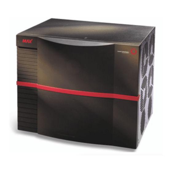
Lucent Technologies MAX TNT Hardware Installation Manual (120 pages)
Brand:
Lucent Technologies
| Category:
Switch
| Size: 2 MB
Table of Contents
Hardware Installation Guide
1
Customer Service
3
Obtaining Technical Assistance
3
Table of Contents
5
About this Guide
13
What Is in this Guide
13
What You Should Know
13
Documentation Conventions
14
Documentation Set
15
Chapter 1 Introduction
17
MAX TNT Features Overview
17
MAX TNT System Overview
18
MAX TNT Shelf
18
MAX TNT Supported Slot Cards
18
Table 1-1 MAX TNT Slot Cards and Their Port Speeds and Capacity
18
Chapter 2 Preparing for Installation
21
Before You Begin
21
Checking the Package Contents
22
Figure 2-1 MAX TNT Shelf
22
Selecting the Installation Site
23
Required Installation Tools and Equipment
23
Understanding the Unit's Back Panel
24
Figure 2-2 Back Panel of the MAX TNT
24
Understanding the Shelf-Controller Back Panel
25
Figure 2-3 MAX TNT Shelf-Controller Back Panel
25
Table 2-1 Description of Shelf-Controller Back-Panel Items
25
Figure 2-4 Location of the MAX TNT Status Lights
26
Status Lights on the Shelf-Controller Back Panel
26
Table 2-2 MAX TNT Status Lights
26
Chapter 3 Installing a MAX TNT Chassis
29
Guidelines for Installing Units in a Rack or Cabinet
29
Rack-Mounting a MAX TNT Unit
30
Figure 3-1 Installing the MAX TNT Rack Ears
31
Figure 3-2 MAX TNT Dimensions
32
Figure 3-3 Mounting the MAX TNT in a Rack
33
Installing a MAX TNT Exhaust Shield
34
Figure 3-4 Exhaust Shield Installed in a Rack
34
Installing or Replacing High-Output Power Supplies
35
Before You Begin
35
Identifying the High-Output Power Supply
35
Figure 3-5 Identifying the High-Output Ac Power Supply
35
Installing a High-Output Power Supply
36
Figure 3-6 Identifying the High-Output DC Power Supply
36
Figure 3-7 Unscrewing the Power Supply
36
Figure 3-8 Removing the Power Supply
37
Figure 3-9 Inserting the Power Supply
37
Connecting the MAX TNT Ac Power Supply
38
Connecting the MAX TNT DC Power Supply
38
Figure 3-10 Tightening the Power Supply Lockscrews
38
Connecting a Workstation to the Serial Port
39
Figure 3-11 Connecting to DC Power
39
Figure 3-12 Connecting a Serial Cable to a MAX TNT Unit
39
Connecting a MAX TNT Unit to the LAN
40
Connecting a Workstation to the Serial Port
40
Figure 3-13 Connecting an Ethernet Cable
40
Checking the Presence of the PCMCIA Card
41
Powering on a MAX TNT Unit
42
Installing or Replacing Slot Cards
43
Identifying Slot Cards
43
Installing a Long-Lock-Screw Slot Card
44
Figure 3-15 Identifying Long, Medium, and Short Lock Screws
44
Figure 3-16 Inserting a Slot Card into a MAX TNT Chassis
44
Installing a Short or Medium Length Lock-Screw Slot Card
45
MAX TNT Hardware Installation Guide
45
Figure 3-17 Lock Screw and Jack Screw Locations
45
Removing Slot Cards
46
Figure A-1 DS3-ATM Card
48
Table A-1 DS3-ATM Card Specifications
48
Appendix A Slot Card Specifications and Connection Information
49
DS3-ATM Card
49
Connecting the DS3-ATM Card to the WAN
50
Connecting Redundant DS3-ATM Cards
50
Figure A-2 DS3-ATM Redundant Configuration
50
Table A-2 DS3-ATM Card Status Lights
50
DS3-ATM2 Card
51
Figure A-3 DS3-ATM2 Card
51
Table A-3 DS3-ATM2 Status Lights
51
Connecting Redundant DS3-ATM2 Cards
52
Connecting the DS3-ATM2 Card to the WAN
52
Figure A-4 DS3-ATM2 Redundant Connection
52
E1 Card
53
Figure A-5 E1 Card
53
Figure A-6 Connecting a MAX TNT Unit's E1 Line to the WAN
54
Monitoring the E1 Lines with Bantam Jacks
55
Table A-4 E1 Card Specifications
53
E1 Frameline Card
55
Figure A-7 E1 Frameline Card
55
Table A-5 E1 Frameline Card Specifications
55
E3-ATM Card
56
Specifications
56
Figure A-8 E3-ATM Slot Card
56
Table A-6 E3-ATM Slot Card Specifications
56
Status Lights
57
Table A-7 E3-ATM Slot Card Status Lights
57
Connecting an E3-ATM Slot Card to the WAN
58
Connecting Redundant E3-ATM Slot Cards
58
Figure A-9 E3-ATM Redundant Configuration
58
Ethernet-2 Card
59
Figure A-10 Ethernet-2 Card
59
Table A-8 Ethernet-2 Card Specifications
59
Ethernet-3 Card
60
Table A-9 Ethernet-3 Card Specifications
60
Table A-10 Ethernet-3 Card Status Lights
60
Ethernet 3-ND Card
61
Specifications
61
Status Lights
61
Figure A-11 Ethernet 3-ND Slot Card
61
Table A-11 Ethernet 3-ND Slot Card Specifications
61
Table A-12 Ethernet 3-ND Slot Card Status Lights
61
Hybrid Access Cards
62
Multidsp Cards
63
48-Port Multdsp Card
63
96-Port Multidsp Card
63
Figure A-12 Multidsp Card
63
Table A-13 Multidsp Card Specifications
64
OC3-ATM Card
65
Table A-14 OC3-ATM Card Specifications
65
Table A-15 OC3-ATM Card Status Lights
66
PCTFI Card
67
Specifications
67
Status Lights
67
Figure A-13 PCTFI Card
67
Table A-16 PCTFI Card Specifications
67
Connecting the PCTFI Slot Card to the Switch
68
Table A-17 PCTFI Card Status Lights
68
Series56 Digital Modem Cards
69
Figure A-14 Series56 II or Series56 III Digital Modem Card
69
Table A-18 Series56 II and Series56 III Digital Modem Card Specifications
69
Card
70
Table A-19 STM-0 Card Specifications
70
Table A-20 STM-0 Card Status Lights
71
SWAN Card
72
Figure A-15 SWAN Card
72
Table A-21 SWAN Card Specifications
72
Connecting the SWAN Card to the WAN
73
Figure A-16 Connecting the SWAN Card to the WAN
73
T1 Card
74
Figure A-17 T1 Card
74
Table A-22 T1 Card Specifications
74
Connecting the T1 Card to the WAN
75
Figure A-18 Connecting the MAX TNT Unit T1 Card to the WAN
75
Monitoring the T1 Lines with Bantam Jacks
75
T1 Frameline Card
76
Figure A-19 T1 Frameline Card
76
Table A-23 T1 Frameline Card Specifications
76
T3 Card
77
Figure A-20 T3 Card
77
Table A-24 T3 Card Specifications
77
Connecting the T3 Card to the WAN
78
Table A-25 T3 Card Status Lights
78
Unchannelized DS3 Card
79
Figure A-21 Unchannelized DS3 Card
79
Table A-26 Unchannelized DS3 Card Specifications
79
Connecting the Unchannelized DS3 Card to the WAN
80
Appendix B Cabling and Connector Specifications
81
Serial Port Specifications
81
Table B-1 Serial Port and Cabling Pinouts
81
Ethernet Interface Specifications
82
Supported Ethernet Types
82
Required Equipment
82
T1/PRI Interface Specifications
82
T1/PRI CSU Requirements
83
Table B-2 CSU Specifications
83
T1/PRI Cable Specifications
84
Figure B-1 RJ-48C/RJ-48C Crossover Cable
84
Table B-3 RJ-48C/RJ-48C Crossover Cable Specifications
84
Figure B-2 RJ-48C/RJ-48C Straight-Through Cable
85
Table B-4 RJ-48C/RJ-48C Straight-Through Cable Specifications
85
Figure B-3 RJ-48C/DB-15 Straight-Through Cable
86
Table B-5 RJ-48C/DB-15 Straight-Through Cable Specifications
86
Figure B-4 RJ-48C/DB-15 Crossover Cable
87
Table B-6 RJ-48C/DB-15 Crossover Cable Specifications
87
Figure B-5 RJ-48C/Bantam Straight-Through Cable
88
Table B-7 RJ-48C/Bantam Straight-Through Cable Specifications
88
T1/PRI WAN Connectors
89
WAN Switched Services Available to a MAX TNT Unit
89
Table B-8 RJ-48C-Loopback Plug Specifications
89
Table B-9 Transmit and Receive Pins
89
E1/PRI Interface Specifications
90
Figure B-6 RJ-48C/RJ-48C Crossover Cable
90
Figure B-7 RJ-48C/RJ-48C Straight-Through Cable
91
Table B-11 RJ-48C/RJ-48C Straight-Through Cable Specifications
91
Figure B-8 RJ-48C/DA-15 Straight-Through Cable
92
Table B-12 RJ-48C/DA-15 Straight-Through Cable Specifications
92
Figure B-9 RJ-48C/DA Crossover Cable
93
Table B-13 RJ-48C/DA Crossover Cable Specifications
93
Figure B-10 RJ-48C/Bantam Straight-Through Cable
94
Table B-14 RJ-48C/Bantam Straight-Through Cable Specifications
94
E1/PRI WAN Ports
95
Table B-15 Transmit and Receive Pins
95
Table B-16 V.35 Cable Pinouts
95
Table B-10 RJ-48C/RJ-48C Crossover Cable
90
Serial WAN (SWAN) Cable Specifications
96
RS-449 Cable to WAN
97
Table B-17 RS-449 Cable Pinouts
97
Serial WAN Cable
98
Table B-18 Serial WAN Cable Pinouts
98
Figure B-11 Serial WAN Cable
99
Table B-19 IDSL Cable Pinouts
100
IDSL Cable Specifications
104
Figure B-12 HDSL Dual 50-Pin Telco-To-Triple-DB-37 Cable
104
ADSL Cable Specifications
105
Table B-20 ADSL Cable Pinouts
105
Figure B-13 ADSL 50-Pin Telco-To-Quadruple DB-37 Cable
107
Table B-21 SDSL Cable Pinouts
107
Table B-22 Cable Pinouts for the 50-Pin Telco Connector
109
SDSL Cable Specifications
110
Figure B-14 SDSL 50-Pin Telco-To-Dual-DB-37 Cable
111
Appendix C Safety-Related Electrical, Physical, and Environmental Information
113
Electronic and Electrical Specifications
113
Battery
113
Electrical Requirements
114
Ground Wire Size
114
Governmental Notices
114
Table C-1 MAX TNT Electrical Requirements
114
Table C-2 Ground Wire Size
114
USOC Jacks and Codes
115
Alarm-Relay Operating Specifications
115
Physical Specifications
115
Environmental Specifications
116
Index
117
Advertisement
Advertisement
Related Products
Lucent Technologies Definity TN500
Lucent Technologies Voice Terminal 8403
Lucent Technologies MAX 6000
Lucent Technologies MAX 3000
Lucent Technologies 4ESS
Lucent Technologies 4ESS SCS
Lucent Technologies 5ESS
Lucent Technologies 5ESS-2000
Lucent Technologies A500
Lucent Technologies B-STDX
Lucent Technologies Categories
Telephone
Switch
Conference System
Software
Telephone System
More Lucent Technologies Manuals
Login
Sign In
OR
Sign in with Facebook
Sign in with Google
Upload manual
Upload from disk
Upload from URL