
Related Manuals for Strebel VARAN 1.14


Summary of Contents for Strebel VARAN 1.14
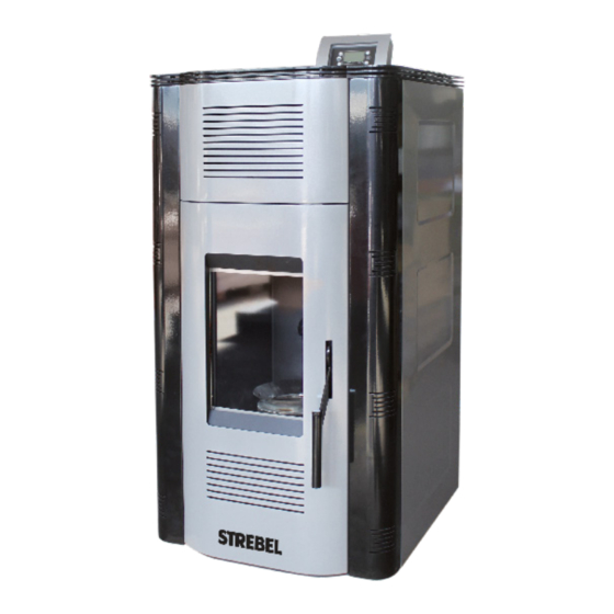
- Page 1 Pellet Boiler Varan 1.14., 1.20 Ökotec 25 Manual For Installation And Useage Aufstellungs- und Product Information Bedienungsanleitung Produktinformation...
- Page 3 This boiler may only be used for the purposes it is intended and was manufactured according to current safety requirements. In- To replace defective parts of the boiler, only use original STREBEL correct use may cause damage to the boiler or to other objects in spare parts.
- Page 4 Varan 1.14, 1.20 Safety Instructions Possible Risks Fresh Air Intake If the combustion chamber door or cleaning openings are left open Boilers need a suitable air supply to maintain combustion. during operation, carbon monoxide is able to discharge from the Open Flue: Under certain circumstances, if the fresh air is ta- boiler.
-
Page 5: Table Of Contents
11 Boiler Disposal ..........................32 1 Boiler Features 1.1 General Information The STREBEL Varan 2.20 is a pellet boiler for aquiferous cen- tral heating systems with radiators and/or underfloor heating. It is designed to be set up directly in the living space (without an external boiler room neded). -
Page 6: Technical Data
230 V /50 Hz 1“ 1“ Connections flow/return Inch 135/90 135/90 Flue gas temperature (rated output, min. output) °C Energy label (Range A++ to G) Changes in models reserved. Dimensions not binding! Schematic section Varan 1.20 Schematic section Varan 1.14... - Page 7 Die Asche wird in einen feuerfesten Behäl- ter ausgeklopft. Danach die Schale wieder einsetzen. Varan 1.14, 1.20 Technical Data Abmessungen und Anschlüsse 2.1 Dimensions (in mm) Varan 1.14 Varan 1.20 Varan 2.20 Filling valve Füllhahn Filling valve Füllhahn Fü Fresh air...
-
Page 8: Fuel
Varan 1.14, 1.20 Fuel 3 Fuel 3.1 Required Fuel Quality The boiler is construdef only for the combustion of wood pellets. Using any other fuel is prohibited. In any case, do not use pieces of wood, paper, oil, plastic or other materials as fuel. -
Page 9: Construction
Varan 1.14, 1.20 Construction 4. Construction 4.1 Boiler Main Parts Flue gas fan Gear motor Controller Pellet tank Cover Cleaning opening Heat exchanger Expansion vessel (10 litres) with turbolators Controller processor Door with special glass Combustion chamber Ash tray Pellet auger... - Page 10 Varan 1.14, 1.20 Construction 4.2 Electrical Scheme The hatched lines are wires which the qualified personnel must connect to the controller during installation. Connectors of additional appliances have to pass via two connectors on the boiler backside. The connectors are bi-pole or tri-pole. The tri-pole connector is used to connect a room thermostat.
- Page 11 Radiators, underfloor heating system (via temperature limiter) Thermal valve (min. 55°C) Always make sure to comply with regional prescriptions when installing a boiler. STREBEL does not take responsibility for damages caused by a faulty installation of the boiler. Changes in models reserved. Dimensions not binding!
-
Page 12: Installation
Varan 1.14, 1.20 Installation 5 Installation 5.1 General Warnings Mind regional prescriptions and legal guidelines during installa- tion, operation and disposal of the boiler. The boiler must be ins- talled by qualified personnel. Water pressure switch This boiler is designed to run in aquiferous central heating instal- lations with an operating pressure of max. - Page 13 Montage of the flue pipes and air supply for combustion: is prescribed. The STREBEL Varan has an exhaust and an air supply The air supply from outside of the building for combustion must be guaranteed. Use a pipe consisting of black or Inox connection on its back side.
- Page 14 The top of the chimney must be protected with a chimney cap due for the impact of rain and winds. Distance of chimney to cap is 200 mm. Situation 1 Chimney Connection Varan 1.14 Air supply connection Exhaust connection Changes in models reserved.
- Page 15 Varan 1.14, 1.20 Installation Situation 1 Chimney connection Varan 1.20 Air supply connection Exhaust connection Changes in models reserved. Dimensions not binding!
- Page 16 Varan 1.14, 1.20 Installation Situation 2: Important: We recommend to perform a chimney evaluation prior to installation. In this situation flue pipe must go at least 1.5 meters vertically upwards in the very room where the boiler is placed. Penetrate through the wall and connect the pipe onto the chimney.
- Page 17 Varan 1.14, 1.20 Installation 0 to 1,5 m 1,5 to 3 m over 3 m Changes in models reserved. Dimensions not binding!
-
Page 18: Controller
Varan 1.14, 1.20 Controller 6 Controller The operating parameters the user has access to are visible on the screen. Additional parameters which influence boiler operation are reserved for qualified personnel ans must not be changed without reasons. Controller panel with buttons and screen... - Page 19 Varan 1.14, 1.20 Controller Scheme of the controller panel with all possible activated parts, dots L1–L12 Function Description Part Electrical igniter Dot visible: The igniter is active Pellet auger Dot visible: The auger motor is active. The auger transports pellets into the combus- tion chamber.
- Page 20 Varan 1.14, 1.20 Controller 6.2 Aufrufen des Menüs Hold button P3 (SET) to open the menu. Use the arrow keys to select a menu item and confirm the choice with P3 (SET). Menu item Description Combustion Power Modification of the combustion programmes: AUTO, P1, P2 oder P3 Heating Power Not used.
- Page 21 Varan 1.14, 1.20 Controller 6.4 Change Combustion Power 6.9.1 ‚Modality‘ sub menu Choose between ‚Modality‘ and ‚Program‘ and confirm the Parameter Description selection with P3 (SET). Operation with power level 3 ‚Modality‘ lets you choos between: ‚Daily‘, ‚Weekly‘, ‚Weekend‘ and ‚Disable‘.
-
Page 22: Remote Control
Varan 1.14, 1.20 Controller Examples for possible programming in the ‚Program‘ sub menu 8.2.8 Combustion Recipe Menu Menu to select the Combustion Recipe. The maximum value is the number of recipes visible to the user. This value can be set in System Menu Default Settings (parameter P04). -
Page 23: Language Menu
(the per cent value is set in the Step Calibration Menu of System Menu). The calibration’s effect is valid only in Run Mode and in Modulation for the current recipe. Varan 1.14, 1.20 Controller 8.2.12 Load Menu... - Page 24 Varan 1.14, 1.20 Controller 6.17 System Menu This menu allows settings reserved for qualified personnel. Because of this, the menu is keyword protected. Ex factory, the keyword is 2111. To enter the keyword, confirm the selection ‚System Menu‘ with P3 (SET). Now it is possible to use P4 (^) and P6 (v) to increase or decrease the displayed digit.
- Page 25 Varan 1.14, 1.20 Controller Thermostat Menu Parameter Recommended Description Th01 55 – 65 The boiler switches off if the flue gas temperature sinks below the set value. Th02 45 – 50 The ignition switches of when the flue gas temperature reaches the set point.
-
Page 26: Operating Phases
Varan 1.14, 1.20 Operating Phases 7 Operating Phases 7.1 Start 7.1.1 Filling Tank With Pellets Open the lid of the pellet tank on the top rear of the boiler and fill it with pellets. Only fill it to a level where the lid can still be closed tightly. -
Page 27: Switching Off
Varan 1.14, 1.20 Operating Phases 7.1.3 Starting Pellet Load Activate the pellet dosing system for loading fuel into the combustion plate. This procedure can only be activated if the controller display shows ‚OFF‘ on the main screen. Press P3 (SET);... -
Page 28: Maintenance
Varan 1.14, 1.20 Maintenance 8 Maintenance 8.3 Daily Cleaning During normal boiler runtime, ash is piling up inside the combus- tion chamber. To ensure a problem-free operation, the combustion 8.1 Special Instructions chamber should be cleaned out from ash every day. At standard... - Page 29 Varan 1.14, 1.20 Maintenance Removable Parts When Cleaning Varan 1.14 Ash plate with wing nuts Varan 1.20 Combustion plate Ash plate with wing nuts...
-
Page 30: Possible Malfunctions
Varan 1.14, 1.20 Possible Malfunctions 9 Possible Malfunctions The boiler controller may display the following messages resulting from a malfuntion. Er01 Error – High voltage (even when boiler is not in operation) Er02 Error – High voltage (only when fan is in operation) Er03 Error –... - Page 31 Varan 1.14, 1.20 Possible Malfunctions The boiler is connected to a room thermostat, but does not switch to ignition mode Solution: Check the current room temperature and compare it to the related preset temperature on the boiler. Make sure that the heating cycle is currently in operation. Test the room thermostat for possible malfunction.
-
Page 32: First Start-Up
The first start-up of this boilermay only be carried out by a profes- 11.1 Removal sional of the company STREBEL or an experienced installer. If the start-up is not carried out correctly, the boiler and the system can The boiler removal must be carried out by qualified technicians. - Page 33 Varan 1.14, 1.20 Space For Notes Changes in models reserved. Dimensions not binding!
- Page 34 Varan 1.14, 1.20 Space For Notes...
- Page 35 Varan 1.14, 1.20 Varan 1.14, 1.20 Space For Notes Changes in models reserved. Dimensions not binding!
- Page 36 Strebelwerk GmbH 2700 Wiener Neustadt, Wiener Strase 118, AUSTRIA Telefon +43 (0)2622 235 55-0 +43 (0)2622 253 46 verkauf@strebel.at www.strebel.at NAK, 0217...
Need help?
Do you have a question about the VARAN 1.14 and is the answer not in the manual?
Questions and answers