Advertisement
Quick Links
Advertisement

Related Manuals for Strebel Ca 7s


Summary of Contents for Strebel Ca 7s
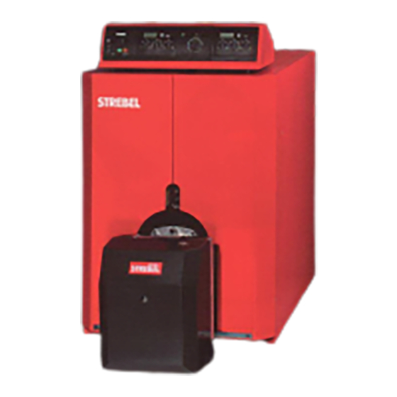
- Page 1 Ca 7s and BCa 7s 61-235 kW INSTALLATION AND OPERATING INSTRUCTIONS Page 1 23/03/01...
- Page 2 CONTENTS: PAGE: Dimensions for Ca7s and BCa7s boilers. 3 & 4 General specification Boiler room clearance requirements Boiler block assembly Pulling up the sections Boiler block assembly & connections Ca7s Jacket assembly Calorifier assembly BCa7s Jacket assembly Continued Electrical connection and Instrument control panel Continued Control module options Control module diagrams...
- Page 3 ASSEMBLY INSTRUCTIONS FOR: Ca 7s / BCa 7s General Specifications Calorifier: The STREBEL Camino 7s is a special boiler for oil or Maximum operating pressure 10 bar gas fired pressure jet burner. Maximum test pressure 13 bar In the BICALOR construction a calorifier for the The boiler can be delived in individual sections supply of hot water is built onto the boiler.
- Page 4 ASSEMBLY INSTRUCTIONS FOR: Ca 7s / BCa 7s Boiler Dimensions Ca 7s - Dimensions KEY: Boiler Flow 130mm NW65 Boiler Return 130mm NW65 35.1 Boiler Drain 3/4” Boiler LK mm Tmm Ca7s-4 Ca7s-5 1015 Ca7s-6 1165 Ca7s-7 1315 1005 Ca7s-8 1465...
- Page 5 ASSEMBLY INSTRUCTIONS FOR: Ca 7s / BCa 7s BCa 7s - Dimensions KEY: Boiler flow 130mm NW65 35.2 HWS drain off ¾” Boiler return 130mm NW65 HWS water connection flow (1½”*) 2” Primary pump 1x230V 1¼” Cold water connection (1½”*) 2”...
- Page 6 ASSEMBLY INSTRUCTIONS FOR: Ca 7s / BCa 7s Diagram showing clearances required in boiler room. The clearance details shown above are required for access to the boilers for maintenance purposes. Slight variations may apply, depending on the specific installation. Page 6...
- Page 7 ASSEMBLY INSTRUCTIONS FOR: Ca 7s / BCa 7s Boiler Block Assembly Once assembled, the boiler block is to be secured with the tie bars (2 at the top, and 2 at the bottom). Prior to The boiler block is assembled by ‘pulling-up’ each screwing nuts up ensure the two disc springs (5)&(6)
- Page 8 ASSEMBLY INSTRUCTIONS FOR: Ca 7s / BCa 7s Brass nut & Pulling-up 2 x M20 Pulling-up M20 Steel nut Rear and Intermediate sections Pulling-up Bars Pulling-up flange Spanner Rear 1st Intermediate section Pulling-up Brass Flange Brass Tighten flanges alternately until faces are touching.
- Page 9 ASSEMBLY INSTRUCTIONS FOR: Ca 7s / BCa 7s The order of assembly from (1) to (7) must be Cold water pressure test: observed. The assembled boiler is to be subjected to a cold water pressure test of 1.5 times the operating pressure.
- Page 10 ASSEMBLY INSTRUCTIONS FOR: Ca 7s / BCa 7s The order of assembly from (1) to (13) must be The jacket assembly should be in the following order: observed. Insulation under the boiler both left and right. Boiler side jackets left and right.
- Page 11 ASSEMBLY INSTRUCTIONS FOR: Ca 7s / BCa 7s Calorifier assembly and connections: Injector tubes (Note: Ensure the holes for the direction of water are facing upwards. Header for the return connection to calorifier. Header for the flow connection to the calorifier.
- Page 12 ASSEMBLY INSTRUCTIONS FOR: Ca 7s / BCa 7s BCa7s Jacket assembly Follow the steps below for completion of the jacket assembly. Page 12 23/03/01...
- Page 13 ASSEMBLY INSTRUCTIONS FOR: Ca 7s / BCa 7s The jacket assembly is completed by following the steps below: • The sensors (4) must be pushed into the sensor pockets at the rear of the boiler (max. of 3 per pocket) Note: •...
- Page 14 ASSEMBLY INSTRUCTIONS FOR: Ca 7s / BCa 7s Instrument Control Panel Description Key: Power On / Off switch. Burner lock-out indicator. (RED) - The red lamp will illuminate if the burner has gone to lock-out. High limit indicator. (ORANGE) - Illuminates if the high limit thermostat is activated. Has to be manually reset by removing cap from STB reset, and press button.
- Page 15 ASSEMBLY INSTRUCTIONS FOR: Ca 7s / BCa 7s B2B Panel The diagrams opposite shows connections to the instrument control panel. Key: Burner Cables Power Supply Connection. Stage 1 & Stage 2 Thermostat Sensor & boiler Thermometer Sensor Pockets. K2B Panel Calorifier Thermostat Sensor Pocket.
- Page 16 ASSEMBLY INSTRUCTIONS FOR: Ca 7s / BCa 7s K2B Connections K2B Electrical Connections Supply 230V / 50Hz Legend Instrument Control Panel. Power Supply 230V / 50Hz Separate Calorifier Control. Burner Connections. (Plug and Socket Looms). Separate Calorifier Circulating Pump. Boiler Circulating Pump Interlock.
- Page 17 ASSEMBLY INSTRUCTIONS FOR: Ca 7s / BCa 7s B2B Instrument Control Panel Connections B2B Electrical Connections Supply 230V / 50Hz Legend Instrument Control Panel. Power Supply 230V / 50Hz Calorifier Circulating Pump. Burner Connections. (Plug and Socket Looms). Boiler Shunt Pump (where applicable) Calorifier Primary Circulating Pump.
- Page 18 ASSEMBLY INSTRUCTIONS FOR: Ca 7s / BCa 7s Page 18 23/03/01...
- Page 19 ASSEMBLY INSTRUCTIONS FOR: Ca 7s / BCa 7s Page 19 23/03/01...
- Page 20 ASSEMBLY INSTRUCTIONS FOR: Ca 7s / BCa 7s IMPORTANT: Flue-gas temperatures of below 160ºC can lead to sooting of the flue, when entering a stone or brick chimney. Where flue-gas temperatures are below 160ºC gross, specially adapted chimneys must be available.
- Page 22 ASSEMBLY INSTRUCTIONS FOR: Ca 7s / BCa 7s THE COMPANY RESERVES THE RIGHT TO CHANGE SPECIFICATIONS AND DIMENSIONS WITHOUT NOTICE STREBEL LTD 1F Albany Park Industrial Estate Frimley Road, Camberley, Surrey, GU16 7PB Telephone: 01276 685422 Fax: 01276 685405 E-mail address: info@strebel.co.uk Website: www.strebel.co.uk...
Need help?
Do you have a question about the Ca 7s and is the answer not in the manual?
Questions and answers