
Subscribe to Our Youtube Channel
Related Manuals for Strebel S-CB+ Series


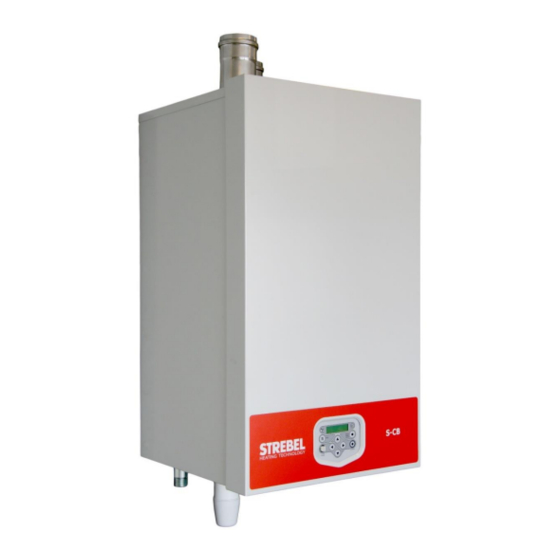
Summary of Contents for Strebel S-CB+ Series
- Page 1 STREBEL S-CB Boiler Range Models 60 - 80 - 100 - 120 - 150 - Wall hung high efficiency condensing boiler Installation, Operating & Maintenance Manual 2015-07-21 v1...
-
Page 4: Table Of Contents
TABLE OF CONTENTS INTRODUCTION…………………………………………………………………………………………….….…...7 SAFETY GUIDELINES ..........................7 TECHNICAL DATA S-CB BOILERS ......................9 ......................9 UNCTIONAL INTRODUCTION ..................10 ECHNICAL SPECIFICATIONS DATASHEET DIMENSIONS .............................12 S-CB 60-120 ..........................12 S-CB 150-180 ..........................13 ACCESSORIES AND UNPACKING ......................14 ..........................14 CCESSORIES ........................... - Page 5 ......................37 LECTRICAL CONNECTIONS ....................37 XPLANATION OF THE CONNECTIONS ......................39 LECTRICAL SCHEMATICS ..........................42 ENSOR VALUES 10 USER INTERFACE ............................43 10.1 ..................... 43 ONTROL PANEL DISPLAY UNIT 10.2 ....................44 ONTROL PANEL MENU STRUCTURE 10.3 ......................46 ISPLAY DURING OPERATION 10.4 ........................
- Page 6 14 ADJUSTING AND SETTING THE BURNER ....................93 14.1 ..........................93 NTRODUCTION 14.1.1 Adjustment tables ......................93 14.1.2 Setting screws gas valve(s): drawings ................95 14.1.3 Gas valve classes A+C and B+J (B+J only for Poland) ............ 96 14.1.4 Adjustment actions: general scheme ................97 14.2 A) ........
-
Page 7: Introduction
The following symbol is used in this manual: Warning: important information concerning the safety of persons and/or the appliance. Strebel Ltd is not accountable for any damage caused by incorrect following the mounting instructions. For service and repair purposes use only original Strebel spare parts. - Page 8 These instructions are written for the installer of Strebel products and contain all necessary information on the in- stallation and adjustment of S-CB Ranges of boilers. Please read these instructions fully before installation to en- sure that all work is carried out correctly.
-
Page 9: Technical Data S-Cb Boilers
TECHNICAL DATA S-CB BOILERS 2.1 Functional introduction The S-CB boilers are central heating boilers with a maximum high efficiency. Such a performance can be reached by, amongst other things, using a special heat exchanger made of stainless steel. This allows the flue gases to cool down below the condensation point, and so release extra heat. -
Page 10: Technical Specifications Datasheet
2.2 Technical specifications datasheet GENERAL Product Identification Number CE 0063 BP3254 Classification II2H3P (for NL II2L3P) Gas Appliance Type B23, B23P; C13X, C23X, C33X, C43X, C53X, C63X, C83X Type boiler S-CB S-CB S-CB 100 S-CB 120 S-CB 150 S-CB Dimensions (h x w x d) 842 x 476 x 486 898 x 476 x 677 Water content estimated... - Page 11 Type boiler S-CB S-CB S-CB 100 S-CB 120 S-CB 150 S-CB EMISSION [EN437] Values min-max: G25/G20 8,7 - 9,0 8,7 - 9,0 8,7 - 9,0 8,7 - 9,0 8,7 - 9,0 8.7 - 9.0 flue gas 9,3 - 10,3 9,3 - 10,3 9,3 - 10,3 9,3 - 10,3 9,3 - 10,4 9.3 - 10.5 G30 (B/P) 9,3 - 10,4 9,3 - 10,4 9,3 - 10,4 9,3 - 10,4...
-
Page 12: Dimensions
DIMENSIONS 3.1 S-CB 60-120 TWIN PIPE CONCENTRIC (Standard Delivery) Concentric twin pipe (Standard Delivery) Connections flue gas 80-80 100-100 80/125 100/150 air inlet size "A" size "B" size "C" N.A. flow R 1¼" (male) condensate flexible hose Ø25/21 x 750 mm return R 1¼"... -
Page 13: S-Cb + 150-180
3.2 S-CB 150-180 TWIN PIPE (Standard Delivery) CONCENTRIC twin pipe Connections concentric (Standard Delivery) flue gas 130-130 100/150 air inlet flow R 1½" (male) condensate flexible hose Ø25/21 x 750 mm return R 1½" (male) R 1” (male) S-CB Boiler Range Manual... -
Page 14: Accessories And Unpacking
ACCESSORIES AND UNPACKING 4.1 Accessories Depending on the selected controlling behaviour for the central heating system and/or the optional use of a calori- fier, the following items can be supplied with the boiler. Ask your supplier for the specifications. Item Part Nº. -
Page 15: Installation Of The S-Cb
INSTALLATION OF THE S-CB 5.1 General notes At every side of the boiler at least 50 mm of clearance should be applied to walls or wall units, 350 mm above the top side of the boiler and 250 mm from the bottom of the boiler. The installation area/room must have the following provisions: ... -
Page 16: Mounting The Boiler
5.2 Mounting the boiler Before mounting and installing the boiler the following connections should be considered: Flue gas system and the flue gas pipe connections Air supply system and connections Flow and return pipe connection Condensate and pressure relief valve drainage ... -
Page 17: Connections Water Side
CONNECTIONS WATER SIDE FRONT VIEW 6.1 Boiler connections 1 – Flow CH 2 – Condensate drain 3 – Siphon cleaning point 4 – Return CH 5 – Gas 6.2 Condensate drain connection The condensate drain is placed at the centre and at the bottom of the boiler and has a ¾... -
Page 18: Flow And Return Connections
6.3 Flow and return connections Two separate T-pieces are shipped with the boiler. These are applied for externally mounting the pressure supplied relief valve and the boiler bleed valve for servicing the with boiler. We advise to install two service valves in the boiler flow and return pipes underneath the boiler, so the BOILER... -
Page 19: Frost Protection
6.8 Frost protection The boiler has a built-in frost protection that is automatically activating the central heating pump when the boiler return (water) temperature drops below the 5°C (programmable). When the boiler return temperature drops below the 3°C (programmable), the burner is also ignited. The pump and/or burner will shut down as soon as the return temperature has reached the 10°C (programmable). -
Page 20: Plastic Piping In The Heating System
6.11 Plastic piping in the heating system When plastic pipes are used in the central heating system, these should be separated from the boiler system by using a plate heat exchanger. Diffusion (through the plastic) can cause air to enter the heating system. This could damage the boiler, pumps and other components in the system. -
Page 21: Chemical Water Treatment
The chemical compatibility of several products for treatment of the central heating equipment has been tested on the heat exchangers and the boilers. A list with the corrosion inhibitors in preventative and curative treatment for gas fired central heating boilers can be supplied by Strebel Ltd. 6.16 Under floor heating When using an under floor heating system, the boiler circuit must be separated from the heating circuit with a plate heat exchanger. - Page 22 S-CB Boiler Range Manual...
-
Page 23: Example Of A Multiple Boiler Heating Circuit With Low Loss Header
6.18.2 XAMPLE OF A MULTIPLE BOILER HEATING CIRCUIT WITH LOW LOSS HEADER NON RETURN VALVE BOILER BOILER (low resistance type) NOT SPRING LOADED HEATING ZONE S-CB Boiler Range Manual... -
Page 24: Pump Characteristics
PUMP CHARACTERISTICS 7.1 Hydraulic graphs S-CB Boiler and pump graph . UPML 25-105PWM: S-CB Boiler and pump graph . UPML 25-105PWM: S-CB Boiler Range Manual... - Page 25 S-CB Boiler and pump graph . UPML 25-105PWM: S-CB Boiler and pump graph . UPML25-105 PWM: S-CB Boiler Range Manual...
- Page 26 S-CB Boiler and pump graph . Wilo Stratos Para 30/1-12 PWM: S-CB Boiler and pump graph . Wilo Stratos Para 30/1-12 PWM: Explanation pump graph: The S-CB range is equipped with high efficiency pumps, in the hydraulic graph there is a minimum and maximum head for the pump.
-
Page 27: Pumps: Maximum Electrical Power
7.2 Pumps: maximum electrical power General - The start current of a conventional pump is approximately 2½ x its nominal current. - The maximum switch current of the PCB is 5 A. When the two statements are combined, the conclusion is that nominal currents of pumps, controlled by the PCB, may not exceed 2 A. -
Page 28: Air Supply
8.2 Air supply When an air supply duct is connected from the outside of the building to the boiler, the boiler will operate as a room-independent boiler (closed boiler). The air supply duct can be made of: PVC / PP ... -
Page 29: Pipe Heights And Mutual Distances On A Flat Roof
8.5 Pipe heights and mutual distances on a flat roof Height A This is the height of the air inlet. A rain hood should prevent rainwater entering the air supply system. When the inlet and outlet are mounted on a flat roof, the inlet should be at least 60 cm above the roof surface and at least 30 cm above the maximum snow level. -
Page 30: Flue Gas And Air Supply Resistance Table
8.8 Flue gas and air supply resistance table In the next section, for five typical flue gas outlet & air inlet configurations the maximum lengths of the straight pipes will be calculated. First all component resistance values are given in the next table: FLUE GAS OUTLET FLUE GAS PIPING Ø... -
Page 31: Five Typical Examples
8.9 Five typical examples Twin pipe system with separate pipes for flue gas and air supply C13, C33, C43, C63, C93 Twin pipe system with separate pipes and concentric roof terminal C13, C33, C43, C63, C93 Single pipe for flue gas outlet only (air supply from boiler room) B23, B23P, B33 Concentric pipe for flue gas/air supply (roof-mounted) C13, C33, C43, C63, C93... - Page 32 Examples A and B maximum pipe lengths Concentric roof terminal concentric/parallel adaptor Flue outlet Air inlet Example B Example A Example A S-CB S-CB S-CB S-CB boiler type S-CB 60 S-CB Diameter air inlet [mm] Diameter flue outlet [mm] Diam.
-
Page 33: Example C: Single Flue Gas Outlet. Air Supply From Boiler Room
8.9.3 C: S XAMPLE INGLE FLUE GAS OUTLET IR SUPPLY FROM BOILER ROOM Boiler type: S-CB Diameter: 100 mm Number Pa total Straight tube m¹ total Bend 90° Bend 45° Flue outlet H/D = 1,0 15,2 15,2 Total resistance flue gas outlet: 79,2 Calculation example with given lengths: checking resistance The total resistance is less than 200 Pa. - Page 34 Example C maximum pipe lengths Flue outlet Air inlet Vented area Example C Example C S-CB S-CB S-CB S-CB boiler type S-CB S-CB Diameter air inlet [mm] Diameter flue outlet [mm] Diam. roof terminal [mm] Maximum pipe length 36,5 21,5 46,5 27,5...
-
Page 35: Example D: Concentric Flue Gas/Air Supply Pipe (Roof-Mounted)
8.9.4 D: C XAMPLE ONCENTRIC FLUE GAS AIR SUPPLY PIPE ROOF MOUNTED Calculation example with given lengths: checking resistance Boiler type: S-CB Diameter: 80/125 mm. Number Pa total Adaptor conc./par. 80/125 Straight tube m¹ total Bend 90° Bend 45° Concentric terminal roof Total resistance flue gas outlet and air supply (concentric):... - Page 36 Examples D and E maximum pipe lengths concentric roof terminal concentric wall terminal Example D Example E Example D S-CB S-CB S-CB S-CB boiler type S-CB S-CB Diameter concentric pipe [mm] 80/125 80/125 100/150 100/150 Concentric roof terminal [mm] 80/125 80/125 100/150...
-
Page 37: Electrical Installation
ELECTRICAL INSTALLATION 9.1 General All the wiring is connected to a separate connector that is fitted in a socket. The connector can be taken from the sockets without loosening the wiring. The connections are placed on top of the display panel and can be accessed by removing the boiler front door and the connector protection cover. - Page 38 GENERAL BLOCKING A heat demand that will start the burner will be blocked when terminals 7 and 8 are not bridged. This connection is for the use of external safety devices (terminals must be bridged for allowing burner to fire). 9-10 EMPTY 11-12...
-
Page 39: Electrical Schematics
9.4 Electrical schematics S-CB Boiler Range Manual... - Page 40 internal connections ionisation and/or ignition siphon pressure switch (PSW) N.C. display ref.1 clixon/maximum (S7) water thermostat 24vdc CN15 WIRING COLORS fan Hall fan control K0=white K6=blue fan PWM CN10 K1=yellow K7=red +24Vdc K2=brown K8=black PWM pump control K3=green K9=purpl K4=grey K10=yello K5=orange flow sensor ntc (S1) 10K...
- Page 41 display boiler casing CN15 ignition transformer incl. ionisation input. WIRING COLORS K0=white K6=blue CN10 K1=yellow K7=red K2=brown K8=black K3=green K9=purple K4=grey K10=yellow/green K5=orange CN12 CN11 CN not used CN10 On/Off Stat BURNER LOCK-OUT HEAT BURNING Divertor Valve Calorifier DEMAND OpenTherm 0 - 10 CH System Mains 230 VAC...
-
Page 42: Sensor Values
9.5 Sensor values SENSOR SENSOR TYPE SENSOR VALUE internal flow sensor NTC-10K-B3977 internal return sensor NTC-10K-B3977 external flow sensor NTC-10K-B3977 calorifier/tank sensor NTC-10K-B3977 outdoor sensor NTC-12K-B3740 flue gas sensor NTC-10K-B3977 Conversion table temperature vs. resistance outdoor sensor NTC-12k B3740 Temperature Resistance Temperature Resistance... -
Page 43: User Interface
USER INTERFACE 10.1 Control panel / display unit CONTROL PANEL DISPLAY 2 rows/ each 20 characters ON/OFF MENU RESET ENTER SERVICE COMM. PORT Press and hold for six seconds to switch boiler on/off. ON/OFF Is also used as RESET button and ENTER button when RESET ENTER programming. -
Page 44: Control Panel Menu Structure
10.2 Control panel menu structure BASE SCREEN : (appears during operation) HEATING : No demand / Standby / burning NOTICE: Pressing too > > > : 1 1 8 ° C ( 1 2 5 ° C ) long will switch off the boiler. - Page 45 HOW TO CONFIRM CHANGES When changes have been made in one of the nine menus below, the user presses ENTER to confirm these changes. To prevent anyone from making changes by mistake, the following happens when changes are made: Step 1: The user presses [ENTER] to confirm the change made or [MENU] to exit the menu without changes.
-
Page 46: Display During Operation
10.3 Display during operation During normal operation the text in the display shows the status of the boiler. In the following graphs the several displays during normal operation are explained. Display at HEATING DEMAND Heat demand type: Actual status: I N G : N o d e m a n d >... -
Page 47: Monitor Screens
10.4 Monitor screens During normal operation and stand-by, the [◄] and [►] buttons can be used to show some boiler information, in- cluding measured temperatures, settings and data. In the following graphs is explained which values can be shown in the display. When no button is activated for 2 minutes, the display will return to its status display. Pressing [◄] or [►] while being at the "operating screen"... - Page 48 SCREEN: C a s c D e s i g n 0 = MASTER, 1 ..11 = SLAVES C a s I n f 0 1 2 3 4 5 6 7 8 9 A B Displays number, priority and state of cascade boilers. DESCRIPTION "CASCINFO"...
-
Page 49: Service Function
10.5 Service function The following graphs describe how to use the service function. Operating screen: H E A T I N G : N o d e m a n d > > > : 1 2 3 . 4 ° C ( 1 2 3 . 4 ° C ) Press [SERVICE] and hold for 3 seconds. -
Page 50: Schornsteinfeger Function
10.6 Schornsteinfeger function The following graphs describe how to use the Schornsteinfeger function. NOTICE: This function is required for Germany and can be activated by parameter (P5 BK). The standard factory setting for this function is “OFF”. The purpose of this function is to have an easy interface for the "Schornsteinfegers"... -
Page 51: Programming In Standby Mode
10.7 Programming in standby mode Standby Use the standby mode for modifying boiler settings without interaction with the boiler control. Changes are effectu- ated by leaving standby mode. Properties of standby mode: Keys are active and the menu is accessible. ... -
Page 52: Set Points
10.9 Set points The following graphs describe how to program the heating and hot water set points. NOTICE: The hot water set points are only displayed, when the boiler is programmed as an indirect hot water boiler or direct hot water boiler. See parameter P4 AA for the exact boiler configuration. Operating screen: H E A T I N G : b o i l e r... -
Page 53: Setting The Timer Programs
DHW set point normal/day time: (parameter P4 AA = 1/2) D H W s e t p o i n t ° C This is the water temperature set point that is active during the programmed DHW periods (parameter P4 AA = 1/2). DHW set point reduction: (parameter P4 AA = 1/2) D H W R e d u c e... - Page 54 HEATING PROGRAM Three programmed periods each day can be set (period 1, period 2 and period 3). During these periods the unit will use the normal CH and DHW set points. Outside the programmed period(s) the unit will use the reduced tempera- ture as set point.
- Page 55 HOT WATER PROGRAM > > > From previous page with HEATING part < < < Setting DHW program times: P r o g r a m D H W M o n 2 3 : 0 0 Press [►] to browse through the values that can be set at the bottom line.
-
Page 56: Setting The Outdoor Specifications
ANTI LEGIONNAIRES' DISEASE PROGRAM The anti-Legionnaires’ disease (pasteurisation) program of the boiler can only be used when the boiler is set as an “indirect” boiler configuration or a “direct” hot water boiler configuration. Only these configurations can activate the day and time program of the anti-Legionnaires’ disease function. See the following graphs. The standard factory setting for this function is “OFF”. - Page 57 OUTDOOR GRAPH (see also next page) HEATING CURVE - main settings P5 AD - Flow temp at outdoor temp low P6 BC - Parallel shift P5 AF - Flow temp at outdoor temp high OUTDOOR TEMPERATURE P5 AE P5 AC outdoor temp high outdoor temp low P5 AC...
- Page 58 HEATING CURVE - additional settings P6 BA - max flow temp P6 BB - Heatcurve night shift P5 AH - Warm weather shutdown P2 HA - Outdoor sensor hysteresis P5 AG - min flow temp OUTDOOR TEMPERATURE P5 AG Heat curve minimum flow temperature (°C) The set point will never be lower than the flow temperature set in parameter P5AG.
- Page 59 DISPLAY The following graphs describe how to program the outdoor graph settings. Operating screen: H E A T I N G : b o i l e r > > > : 1 2 3 . ° C ( 1 2 3 4 °...
-
Page 60: Checking The Operating History
10.12 Checking the operating history The following graphs describe how to check the operating history of the boiler. Operating screen: H E A T I N G : b o o f f > > > : 1 2 3 . 4 ° C 1 2 3 . -
Page 61: Checking The Fault History
10.13 Checking the fault history The following graphs describe how to check the fault history of the boiler. Operating screen: H E A T I N G : b o l e r o f f > > > : 1 2 3 . 4 °... -
Page 62: Setting The Maintenance Specifications
10.14 Setting the maintenance specifications The following graphs describe how to check and program the maintenance settings. The standard factory setting for this function is “OFF”. MAINTENANCE SETTINGS The unit can be programmed in such a way that an automatic maintenance message is displayed. There are three options that can be selected. - Page 63 Operating screen: H E A T I N G : N o d e m a n d > > > : 1 2 3 4 ° C ( 1 2 3 . 4 ° C ) Press [MENU] Select "Maintenan" using [◄] & [►] and press [ENTER] Operating screen: M a i n t e n R e s e t...
- Page 64 From previous page Screen: Selecting message at certain date. M a i n t e n M o d e D a t e Press [►] to set: The date for the maintenance message. Press [◄] to: Return to maintenance mode selection. Press [►] to browse through the values that can be set at the bottom line.
- Page 65 From previous page Screen: Message after total amount of burning hours. M a i n t e n M o d e B u r n i n g h o u r s Press [►] to set: The total amount of burning hours for the Maintenance message. Press [◄] to: Return to maintenance mode selection.
-
Page 66: Setting The User Lock
10.15 Setting the user lock The following graphs describe how to activate the user lock of the display. The standard factory setting for this function is “OFF”. The "USER LOCK" menu. In this menu the boiler can be locked for (end-)users. 0 = UNLOCKED 1 = LOCKED When the boiler is unlocked, the user can enter the MENU by... -
Page 67: Setting The Parameters At The Control Panel
10.16 Setting the parameters at the control panel The functions of the controller are embedded in de electronics by means of parameters. The values and settings hereof can be programmed by a skilled and trained service engineer with the help of a computer (laptop), the cor- rect software and an interface cable. - Page 68 Operating screen: H E A T I N G : N o d e m a n d > > > : 1 2 3 . 4 ° C ( 1 2 3 . 4 ° C ) Press [MENU] Select "Parameter"...
- Page 69 Menu A: Heating c P r b ° C Select the cascaded boilers supply temperature control. This parameter is the proportional range of the selected CH supply temperature of EACH boiler of the total cascade and of the external (cascade) sensor. Menu A: Heating l n t S e c...
- Page 70 Menu B: Hot water L e g i o t e m p ° C Pasteurisation function of the boiler. This parameter is the selected hot water temperature during the pasteurisation function of the boiler. Menu B: Hot water L e g i o h y s t °...
- Page 71 Menu B: Hot water D H d s c l n t 2 3 2 0 0 S e c Function for the direct hot water boiler. This parameter is the integration time of the selected HW temperature of the boiler. Menu B: Hot water D H d s c O f °...
- Page 72 Menu C: Cascade Function for the cascading of the boiler(s). This parameter is activated when an external (extra) boiler is connected to the Master boiler. Connect to the Master con- nections 21-22. Menu C: Cascade C a s / M a Function for the cascading of the boiler(s).
- Page 73 Menu D: General M a x C o o l Function for setting the maximum overrun time of the fan (maximum 10 minutes). 0 = Switch off Menu D: General T e m p O n D i Function to show the (measured) temperature of the boiler at the display.
-
Page 74: Fault Codes Display
10.17 Fault codes display The following graphs describe the lock out codes of the boiler. A lock out code can only be removed by a manual resetting of the boiler. NOTICE: Before resetting the boiler always check the boiler, central heating system and all components corres- ponding to the related lock out description. - Page 75 a m e Display message p u m p 9 9 9 Reason Flame detected during normal operation, but was lost while running. a m e g n a Display message p u m p 9 9 9 Reason Flame signal is detected while it cannot be expected. F a n s p e e d Display message...
-
Page 76: Blocking Codes
10.17.2 B LOCKING CODES The following graphs describe the blocking codes of the boiler. A blocking code is only a temporary blocking of the boiler, because of an extraordinary situation. The boiler will continue to operate after stabilisation of this situation. The display is not blinking, but is lightened up during the blocking period. -
Page 77: Messages
Display message Reason Water pressure is too low or too high. Display message Reason Outdoor temperature has exceeded the blocking temperature which is set in the pa- rameters. Display message Reason Temperature difference between flow and return exceeds the blocking value but not the lock out value. -
Page 78: Controlling Options And Settings
CONTROLLING OPTIONS AND SETTINGS 11.1 General The following paragraphs describe some general functions of the boiler and their possible use. 11.1.1 XTRA BOILER CONTROL When all units (cascaded) are firing at their maximum it is possible to start an extra “external” heating source. This unit can be connected to the “Burner Burning”... -
Page 79: Soft Start Option
PROPANE G31 P PROPAN P4BD = 1 In case of gas conversion, paste the correspond- PROPANO ing sticker at the appropriate position in the boiler PROPAAN and mark the square for the used gas type. Also BUTANE/PROPANE mark the square, indicating that the correct value G30/G31 B/P BUTAN/PROPAN P4BD = 2... -
Page 80: Heating
11.2 Heating The following paragraphs describe the different functions of the boiler and their related “controlling behaviour set- tings” as a central heating boiler. 11.2.1 ONTROLLING BEHAVIOUR SETTINGS The factory settings for all heating applications are working fine and it is therefore advised not to change these settings. -
Page 81: Room Thermostat On/Off
11.2.2 OOM THERMOSTAT ON A room thermostat with a fixed set point and using an ON/OFF control can be connected to the boiler (Connections 13-14). Changing the flow temperature set point and activation of a timer program can be done by this room ther- mostat or by programming the boiler settings. -
Page 82: Vdc Remote Burner Input Control
11.2.6 0-10 V EMOTE BURNER INPUT CONTROL The burner input is controlled by connecting an external 0-10 Vdc signal to the boiler (connections 15-16). P5 BB Analogue input config (0=off 1=temperature 2=power) (display D1) This parameter must be set at "2" so the supplied 0-10V dc signal will control the burner input. The standard factory setting is “1”, temperature set point control. -
Page 83: Indirect Hot Water/Calorifier
11.3 Indirect hot water/calorifier The following paragraphs describe the different functions of the boiler and their related “controlling behaviour set- tings” as a central heating boiler with an indirect hot water function. 11.3.1 UMP AND WAY VALVE CONTROL See chapter 19 for several installation examples of the boiler and the preferred functions. When the boiler is used as an indirect boiler for both central heating and hot water function, this hot water function can be activated by u- sing a DHW pump (calorifier pump (pump 2)) or a 3-way valve. -
Page 84: Low/High Flow Temperature To Tank Coil
11.3.4 HIGH FLOW TEMPERATURE TO TANK COIL This function can only be used for an “indirect” programmed boiler (parameter P4 AA = 1). Normally for a regular calorifier a fixed flow temperature of 85°C is supplied to the calorifier heat exchanger in case of a heat demand. -
Page 85: Heating And Hot Water Switching Time
11.3.5 EATING AND HOT WATER SWITCHING TIME This function can only be used for an “indirect” programmed boiler (parameter P4 AA = 1). In case there is a heating demand and the unit is operating for this heating demand, also a hot water demand can be activated. -
Page 86: Anti-Legionnaires' Disease Function (Pasteurisation)
’ 11.3.7 EGIONNAIRES DISEASE FUNCTION PASTEURISATION This function can only be used for an “indirect” programmed boiler (parameter P4 AA = 1), on which a DHW pro- gram is active. To prevent Legionnaires' disease the boiler (software) provides a function for heating up the hot water storage tank (once a week) to a higher water temperature then the normal active hot water set point. -
Page 87: Cascade Control
11.4 Cascade control The following information is also found in the specific cascade manual, supplied standardly with Strebel cascade accessories or on request. Before commissioning a cascade installation, a number of parameters have to be changed. These parameters can be programmed on the unit itself, without the use of a computer. - Page 88 Now for every single boiler of the cascade the following two parameters must be selected and programmed accord- ing to the above drawing. Master: Menu C: Cascade C5 P5 DF 1 C a s / M a C2 P5 DA 0 Function for the cascading of the boiler(s).
-
Page 89: Monitor Screens
When cascade connection is programmed correctly the boiler display will show the following. Explanation "Cascade communication indicator" NO CASCADE COMMUNICATION > > > no.1 Always showing the fixed ">>>" CORRECT CASCADE COMMUNICATION > > no.1 no.2 > Showing alternating no.1 & no.2 with 1 second interval. 11.4.2 ONITOR SCREENS To obtain cascade information, see §... -
Page 90: Commissioning The Boiler
COMMISSIONING THE BOILER 12.1 First: flushing the boiler with water After installation of the boiler the first step, before commissioning, is to flush the boiler and the whole heating instal- lation with fresh water to remove pollution, debris and other materials that might cause a blocking. This must also be done with heating installations, where only the boiler is replaced. - Page 91 By pressing the [SERVICE] button of the boiler, the boiler can be started without a heating demand. The boiler will start to fire and also the pump will start to run. Firing of the boiler without water flow (but filled with water!) will cause the so called “boiling noises”.
-
Page 92: Starting The Boiler
STARTING THE BOILER 13.1 General Check the gas pressure available at the gas connection pipe of the boiler. Use the pressure nipple (3) of the gas safety valve for this measurement. The graphs on page 95 show the position of the pressure nipple (3) for the complete boiler range. The gas input pressure for the boiler to operate properly under the correct load must be more than 20 mbar at high fire. -
Page 93: Adjusting And Setting The Burner
ADJUSTING AND SETTING THE BURNER Before carrying out any adjusting of the burner, carefully read this complete chapter. 14.1 Introduction The burner must always be adjusted in the next situations: - A new boiler is installed - As part of a service/maintenance check, in case the CO values turn out to be incorrect Adjustment procedures for situation A are described in §... - Page 94 Table 2 pre adjustment settings gas valves (G27 for Poland) number of turns open (counter clockwise) boiler type nat. gas G20 / G25 / G27 propane G31 butane G30 (B/P) 0,25 S-CB 0,75 S-CB 1,25 S-CB 2,25 * 0,75 * S-CB 2,25 * 0,75 *...
-
Page 95: Setting Screws Gas Valve(S): Drawings
See § 14.3 on page 98. 14.1.2 ETTING SCREWS GAS VALVE DRAWINGS NOTICE: Do NOT mistake the screw marked ‘PILOT’ for screw 2. Screw 2 is the SMALL screw immediately next to the pilot screw. 80 & 100 150 & 180 S-CB Boiler Range Manual... -
Page 96: Gas Valve Classes A+Cand B+J (B+Jonly For Poland )
14.1.3 G B+J (B+J AS VALVE CLASSES ONLY FOR OLAND These pictures show the difference between an A+C and a B+J valve. Notice the class being denoted on the ID plate of the valve. S-CB Boiler Range Manual... -
Page 97: Adjustment Actions General Scheme
14.1.4 DJUSTMENT ACTIONS GENERAL SCHEME General scheme for adjustment of the gas valve(s). Check this scheme for an overview. To complete all necessary adjustments in right order, follow case A or B top-down through the scheme (B involves a few extra steps (grey text blocks)): GENERAL SCHEME SETTING STEPS case A case B... -
Page 98: Adjusting In Case Of A New Boiler, Or After Maintenance (Case A)
14.2 Adjusting in case of a new boiler, or after maintenance (case A) 14.2.1 ENERAL REMARK For all adjusting steps under A the following must be applied: as long as measured CO values differ less than 0,3% from the table values, no adjustment is necessary, because this deviation is typical for the process (O val- ues: ±... -
Page 99: Checking And Adjusting At Maximum Load A 180
14.3.4 S-CB 120 / S-CB 150 / S-CB HECKING AND ADJUSTING AT MAXIMUM LOAD The boilers S-CB 120, S-CB 150 and S-CB 180 all have double gas valves, see the drawings on page 94. First connect a manometer to "p-out" = measuring point [4] of the left gas valve (see drawing). ... -
Page 100: Adjusting Procedures
14.4 Adjusting procedures Procedures 1 and 2, referred to in the previous sections 14.2 and 14.3, are described here: Procedure 1: adjust at maximum load In case B (replacement of gas valve or gas conversion): consult § 14.3. before starting procedure 1 below. Carry out the next 4 steps: 1. -
Page 101: Putting The Boiler Out Of Operation
PUTTING THE BOILER OUT OF OPERATION It is recommended to have the boiler operational all year round to prevent any frost damage during the winter and/or rotating parts getting jammed during other times of the year (built in boiler safety features). 15.1 Out of operation: on/off function To be used when the appliance must be put out of operation for a long period because of a defect or another safety risk. -
Page 102: Fault Codes. Blocking Codes
FAULT CODES. BLOCKING CODES 16.1 Fault codes IMPORTANT: To avoid electric shocks, disconnect electrical supply before performing troubleshooting. To avoid burns, allow the unit to cool before performing troubleshooting. Be aware that a fault code is an indication that the unit or the system needs attention. When repeatedly having faults these should not be neglected. - Page 103 Display message u r n T e m p p u m p 9 9 9 h r s Reason: Maximum return temperature exceeds limit value. Cause: Systems that pre-heats the boiler return temperature too much/high. Corrective action: Reduce pre heat temperature of external heat source. Cause: The need for heat in the system suddenly drops causing hot return water to the boiler.
- Page 104 Display message e m p t o o p u m p 9 9 9 h r s Reason Flue gas temperature exceeded 3 times limitation value within a certain period. Cause: Heat exchanger polluted and not able to transfer enough heat to system water. Corrective action: Check and clean heat exchanger.
- Page 105 F8 Cause: Ignition spark is present, but no flame results. Corrective action: Check if all gas valves in the supply line are completely open. Check if there is no air in the gas supply (start-up new systems). Check if the gas valve opens. When there is power supply to the gas valve, but the valve does not open, the gas valve must be replaced.
- Page 106 Cause: Bad flue gas and/or air supply system. Corrective action: Check if the design of the flue gas and air supply system complies with the max. com- bined resistance as specified. Check if the flue gas and air supply system is installed according a good installation prac- tice by a skilled installer.
- Page 107 Display message P a r a m / H a r d w p u m p 9 9 9 h r s Reason Failure during programming of the parameters. Cause: Programming of the parameters NOT successfully completed. Corrective action: Unit is not in standby mode (fan must not run during programming).
- Page 108 Display message p h o n s w i p u m p 9 9 9 h r s Reason Siphon pressure switch detects high pressure in the flue/siphon system. Cause: There is too much resistance in the flue gas circuit causing high pressure in the heat ex- changer at the flue gas side.
-
Page 109: Blocking Codes
16.2 Blocking codes: The display is not blinking, but is lightened up during the blocking period. The boiler is blocking an action, because of an extraordinary situation. This action will be continued after stabilisation of this situation. Display message e m p 9 9 9 h r s Reason:... - Page 110 Cause: There is no water in the unit while firing. Corrective action: This is an unlikely situation while all the safeties for checking the water presence didn't detect anything. Only a lot of air in the system/unit (under pressure) can cause the water pressure switch to switch while no water is present.
- Page 111 Display message p u m p 9 9 9 h r s Reason Bad power supply Cause: The supplied power does not comply with the specifications. Corrective action: Check if the power supply is connected correctly to the unit. Check the voltage and frequency (should be Life Neutral, Gnd > 230 Vac / 50 Hz). Make sure there is no signal failing or voltage peaks in the power supply.
-
Page 112: Maintenance Attention Function
Display message C a s c a d e o c k 9 9 9 h r s Reason One of the boilers of the cascade is in a lock-out. Cause: The unit is programmed in such a way that none of the boilers in a cascade will fire, if one has a lockout. -
Page 113: Maintenance
MAINTENANCE 17.1 General For a good, safe and long-time operation of the boiler it is advised to carry out maintenance and service on the boiler at least once a year. Maintenance and inspection of the boiler should be carried out at the following occasions: ... - Page 114 Service history The operational and fault history (total amount and since the last service) of the boiler can be retrieved with the help of a computer, correct software and an interface cable. This information can be used to specify the mainte- nance and service proceedings in relation to the boiler (parts).
- Page 115 When these gaskets have changed colours at some parts, the rubber has cured and/or has damages, these gas- kets must be replaced. Notice: only use the gaskets that are supplied by the boiler manufacturer. S-CB Boiler Range Manual...
- Page 116 When the fan blades are polluted and dirty, carefully clean the blades with a soft brush. Notice: do not use too much force on the blades or else the fan might be out of balance and run irregularly, causing noises and fan fail- ures.
-
Page 117: User Instructions
During service and maintenance the gas, supply air, flue gas and condensate connections are discon- nected, checked and replaced. Make sure that all these components are mounted correctly before com- missioning the boiler again. Cleaning the burner room with acid or alkali products is prohibited. Mounting the burner door correctly back onto the heat exchanger: tighten in given order. -
Page 118: Installation Examples
INSTALLATION EXAMPLES The following schematics present several ways of mounting the heating installation: All schematics are purely functional. Safety components must be added conform all applicable standards and regulations. System Type 1 HEATING ZONE BOILER Code 1 Name Wire terminal Order nr. - Page 119 System Type 4 Code 4 Name Wire terminal Order nr. built-in boiler pump HEATING BOILER ZONE optional heating pump 25-26-27 modulating room unit 13-14 S04.016.355 with timer calorifier calorifier thermostat S04.016.303 or tank sensor outdoor temperature E04.016.585 sensor diverter valve 28-29-30-31 (3-way-valve) Parameter change required...
- Page 120 System Type 7 Code 7 Name Wire terminal Order nr. built-in boiler pump HEATING ZONE BOILER optional heating pump 25-26-27 modulating room unit 13-14 S04.016.355 with timer calorifier calorifier thermostat S04.016.303 or tank sensor low loss header flow temperature sensor E04.016.304 diverter valve 28-29-30-31...
- Page 121 Code 9 Name Wire terminal Order nr. HEATING built-in boiler pump ZONE BOILER optional heating pump 25-26-27 modulating room unit with 13-14 S04.016.355 timer HWS primary pump 29-30-31 calorifier calorifier thermostat S04.016.303 or tank sensor low loss header flow temperature sensor E04.016.304 non return valve (low resistance type)
- Page 122 System Type 11 HEATING BOILER BOILER BOILER BOILER ZONE slave 2 master slave 1 slave 3 Code 11 Name Wire terminal Order nr. built-in boiler pump optional heating pump 25-26-27 modulating room unit with timer 13-14 S04.016.355 non return valve (low resistance type) HWS primary pump 29-30-31 calorifier...
-
Page 123: Index
INDEX 0-10 vdc remote burner input con- fault checking, 61, 74 positioning the boiler, 16 trol, 82 fault codes display, 74 power (supply), 9, 18, 37, 90 0-10 vdc remote flow temperature fault codes. blocking codes, 102 pressure relief valve, 18 set point, 81 firing for the first time, 92 pressure safety valve, 90... - Page 124 S-CB Boiler Range Manual...
- Page 125 Strebel Ltd 1f Albany Park Industrial Estate, Frimley Road, Camberley, Surrey, GU16 7PB. 01276 685422 01276 685405 info@strebel.co.uk www.strebel.co.uk Further information on our complete product range is available from our website. CAST IRON – CONDENSING – STEEL SHELL – WATER HEATERS – RENEWABLES...
Need help?
Do you have a question about the S-CB+ Series and is the answer not in the manual?
Questions and answers
What size gas meter should be fitted to Strebel -S-Cbplus boiler -150K
The suitable gas connection size for the Strebel S-CB+150 boiler is R 1”. Therefore, a gas meter capable of supporting a 1-inch gas connection and the required flow rate for a 150 kW boiler is appropriate.
This answer is automatically generated