
Related Manuals for Strebel Turbotec 20-30


Summary of Contents for Strebel Turbotec 20-30
- Page 1 Installation manual for the authorised specialist Turbotec lambda control 20-100 kW 40, 50L – 100L 20-30, 40S-70 12/2014...
- Page 2 READ THE INSTRUCTION BOOKLET AND THESE SUPPLEMENTARY INSTRUCTIONS CAREFULLY BEFORE INSTALLATION These supplementary instructions together with those further in the instruction booklet cover the basic principles to ensure the satisfactory installation of the boiler, although detail may need slight modification to suit particular local site conditions. In all cases the installation must comply with current Building Regulations, Local Authority Byelaws and other specifications or regulations as they affect the installation of the boiler.
- Page 3 HEALTH AND SAFETY PRECAUTIONS Special care must be taken when installing the boiler such that the requirements of the Health and Safety at Work Act are met. Handling Adequate facilities must be available for loading, unloading and site handling. Fire Cement Some types of fire cement are caustic and should not be allowed to come into contact with the skin.
- Page 4 BOILER PERFORMANCE Refer to the main instruction further in this manual for details of the boiler’s performance. PREPARATORY WORK AND SAFETY CHECKS IMPORTANT WARNING This boiler must not be installed into a chimney that serves any other heating appliance. There must not be an extractor fan fitted in the same room as the boiler as this can cause the boiler to emit fumes into the room.
- Page 5 Any existing chimney must be clear of obstruction and have been swept clean immediately before installation of the lining system. Where the chimney is believed to have previously served an open fire installation it is possible that the higher flue gas temperature from a closed appliance may loosen deposits that were previously firmly adhered, with the consequent risk of flue blockage.
- Page 6 Moreover, subsequent success in doing so. conventional standards and for rectification is always more Best regards Strebel Ltd Unit 1F Albany Park Industrial Estate, Frimley, Camberley Tel: 01276 685422 Fax: 01276 685405 Email: info@strebel.co.uk Thermostrom...
-
Page 7: Table Of Contents
Overview General instructions Area of use/scope of delivery Overview General instructions..........3 Illustration of boiler types 20-70....... 4 General instructions Illustration of boiler type 60 L........5 Installation, assembly, electrical Boiler technical data..........6 connections and first commissioning Boiler dimensions............ 7 are tasks for a qualified expert. -
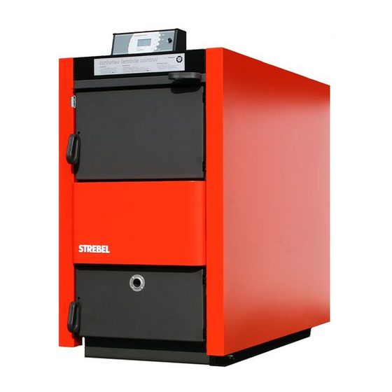
Page 8: Illustration Of Boiler Types 20-70
Overview Boiler illustration 20 - 30, 40S, 50 - 70 1 Computer-controlled lambda 14 Ashes chamber 28 Cladding, left side, with plug-in control 15 Cleaning lid wiring 16 2 sleeves 1/2” 2 Cladding, front lid 29 Transport eye bolt 17 Heat exchanger connection R1/2” 4 Filling door (type 40S-70has two 30 Cladding, right side filling doors) -
Page 9: Illustration Of Boiler Type 60 L
Overview Boiler illustration 50L - 100L (Top loading door optional) 1 Computer-controlled lambda 14 Ashes chamber 28 Cladding, left side, with plug-in control 15 Cleaning lid wiring 16 2 sleeves 1/2” 2 Cladding, front lid 29 Transport eye bolt 17 Heat exchanger connection R1/2” 3 Filling lid 30 Cladding, right side 4 Filling door... -
Page 10: Boiler Technical Data
Storage Minimum Volume litres 1200 1500 1800 2400 2400 3000 3600 4200 3000 3600 5000 8000 tank Recommended by Strebel volume Flue Required outlet pressure mbar 0,10 0,10 0,10 0,10 0,10 0,10 0,10 0,10 0,10 0,10 0,10 0,10 Exhaust fume mass flow... -
Page 11: Boiler Dimensions
Overview Boiler dimensions Turbotec 40 lambda control Turbotec 20 – 30 lambda control Turbotec 40S – 70 lambda control Turbotec 50L – 100L lambda control (Showing optional filling lid centre line) -
Page 12: Control Technical Data
Ambient storage temperature There are several controllers available in the Strebel Turbotec boiler range, each with their own special features. These controllers DO NOT alter the performance of the appliance, only supplementing system/control outputs. Covered in this manual is LC1. -
Page 13: Boiler Room/Air Supply/Installation Site
Overview Boiler room/air supply/installation site Checks following transport Boiler room endangered by a lack of oxygen! clearance must be at least 60 to With regard to the equipment in The supply air must not be 80cm. Do not lay any pipes in the boiler room, the respective contaminated by aggressive the vicinity of the cleaning lid... -
Page 14: Assembly Assembly Of The Cladding With Insulation
Assembly Assembly of the cladding with insulation Assembly of the cladding with cladding (28) for attachment to edge of the side cladding (28, insulation the control later. 30) aligns with the doors at the - Place the rear side cladding - Connect the rear side cladding front. -
Page 15: Flue
Assembly Flue / mounting the air regulation units Mounting the induced draft fan Electrical / Water connection / heating connections Flue Mounting the air regulation Water connections units The flue must be checked by the Filling and draining responsible master chimney Fasten the primary and sweep before the heating boiler secondary air regulator units... -
Page 16: Raising The Return Temperature
Assembly Raising the return temperature Thermal discharge safety device Mounting the O probe and the exhaust fume sensor Raising the return temperature The installation of a hydraulic Thermal discharge safety It is essential to mount a funnel and drain pipe for the ‘thermal unit is mandatory in boilers device discharge safety device’... -
Page 17: Sensor
Assembly Mounting the storage tank sensor Mounting the hydraulic unit Mounting the control Mounting the storage tank - Unpack the control,carefully, Boiler Wilo Pump Rotational sensor unroll the capillary tube of the speed safety temperature limiter (don’t - Insert the storage tank sensor stage into the immersion sleeve on the bend it!) and push it through the... -
Page 18: Hydraulic Diagrams Overview
Strebel. If an LC-E or BSB Control of the return temperature controller is used; see separate Systems 3 and 4: of an oil or gas-fired boiler in controller manual. -
Page 19: Hydraulic Diagram - System 3
Assembly Hydraulic diagram – system 3 Electrical connection diagram System no. 3, which is stored in the control, must be entered for the application cases defined in this installation manual. 1 Turbotec wood gas boiler Return valve with actuator P2 Heating circuit pump 2 Load compensation storage Charging valve with actuator P3 Charging pump, tap water... -
Page 20: System 3
System 3 Assembly System 3 Functional description Important information System 3 heat consumption and the target Turbotec wood gas boiler with boiler temperature that has been Important instruction: load compensation, buffer or set, the load compensation, energy storage tank, tap water buffer or energy storage tank is The setting of a boiler ... -
Page 21: Hydraulic Diagram - System 3.1
1 Turbotec wood gas boiler Return valve with actuator P1 Primary pump 2 Load compensation storage Charging valve with actuator P2 Heating circuit pump tank, buffer storage tank or Four-way valve with actuator P3 Charging pump, tap water energy storage tank Non-return valve or flap storage tank 3 Heating distributor... -
Page 22: Function Description
System 3.1 Assembly System 3.1 Functional description Important information System 3.1 depending on the temperature Important instruction: Turbotec wood gas boiler with difference (between the boiler The setting of a boiler temperature TK S of 85 °C load compensation, buffer or temperature and the storage causes the load energy storage tank, tap water... -
Page 23: Settings For System 3
Assembly Settings for system 3 Settings for system 3 the following appears on the Are you sure ? NO – YES Once the electrical connection display: <-- for System 3 has been made Boiler min. The entry is confirmed by pressing the ‘Arrow’... -
Page 24: Aggregate Test
Assembly Table for noting system settings Aggregate test The control has now been set up Aggregate test The displayed aggregate is switched off by pressing the for the existing system and is Only possible in the operating ‘Minus’ button. ready for operation. The set mode 'Heating OFF'. -
Page 25: Commissioning Instruction/Commissioning/Handover
Commissioning Instruction/commissioning/handover Commissioning the control Setting the boiler temperature Instruction/commissioning/ precise information about this, Heating handover please refer to the ‘Troubleshooting’ section). Following completion of the hydraulic and electrical installation, The main heating switch Commissioning the boiler the boiler must be commissioned by should in principle remain a qualified specialist. -
Page 26: Commissioning The Boiler
Commissioning Commissioning the boiler Heating up/adding fuel - wait until the control switches Adding fuel - Close the interior door and automatically to the operating As a matter of principle, more filling door 1 mode ‘Heating ON’; the following fuel should be added only if the - If necessary, also place wood appears in the text display: fuel has been used up totally,... -
Page 27: Circuit Diagram
Commissioning Circuit diagram... -
Page 28: Short Operating Instructions: Lambda Control Off
Deutsch Englisch KESSELFÜHLER BOILER SENSOR TÜRÖFFNER DOOR OPENER SCHUTZLEITER Kesselseitenwand PROTECTIVE EARTH CABLE boiler side wall SCHUTZLEITER Kesseldeckel PROTECTIVE EARTH CABLE boiler lid NETZ MAINS STECKER 1 PLUG 1 WIRING DEPENDS ON SYSTEM APPLICATION – VERDRAHTUNG JE NACH SYSTEMANWENDUNG - HYDRAULIKSYSTEME 1-3 HYDRAULIC SYSTEMS 1 - 3 SPEICHERFÜHLER... -
Page 29: Short Operating Instructions: Lambda Control On
Commissioning Short operating instructions... -
Page 30: Maintenance Boiler Maintenance
Deutsch English Wärmeerzeugung AUS Heating OFF AUSWAHL SELECTION INFORMATIONEN INFORMATION ENDE Regelprogramm Control program Winterbetrieb Winter operation Höchstwert Highest value Betriebsstunden Operating hours Bereitschaft Standby keine Störung no malfunction EINSTELLUNGEN SETTINGS SOMMERBETRIEB SUMMER OPERATION AGGREGATETEST AGGREGATE TEST Kesselsollwert Boiler set value Servicecode mit Service code with Test... - Page 32 Deutsch English Wärmeerzeugung EIN Heating ON AUSWAHL SELECTION INFORMATIONEN INFORMATION ENDE Regelprogramm Control program Winterbetrieb Winter operation Höchstwert Highest value Betriebsstunden Operating hours Bereitschaft Standby keine Störung no malfunction EINSTELLUNGEN SETTINGS SOMMERBETRIEB SUMMER OPERATION KAMINFEGERTEST CHIMNEY SWEEP TEST AGGREGATETEST AGGREGATE TEST Kesselsollwert Boiler set value Servicecode mit...
- Page 33 Maintenance Boiler maintenance Troubleshooting Maintenance Troubleshooting Measured values of the boiler (Heating to ‘OFF’) temperature are incorrect The control recognises malfunctions automatically and Boiler temperature Door closure bolts executes malfunction-related Measured values wrong The door closure bolts must be alternative programs or safety Causes: plug contact, sensor oiled regularly.
- Page 34 Maintenance Troubleshooting Measured values of the Boiler temperature too low Exhaust fume temperature too storage tank temperature are high Boiler temperature incorrect Exhaust fume too low [C] ### Storage tank temp. temperature Causes: plug contact, cables, Measured values wrong non-return valve, actuator, too high [C] ### Causes: plug contact, sensor control.
- Page 35 Notes...
- Page 36 Please contact Strebel to arrange commissioning or training by our own engineers, if required! We would like to thank you very much for placing your trust in Strebel, you will get many years of pleasure from your new boiler!
- Page 37 Signature HYDRAULIC AND SAFETY DEVICES REMARK System no.: ………. System assembled according to Strebel hydraulic diagrams Boiler and system vented, system pressurised, stop valves open Thermal discharge safety device connected (primary pressure 2 bar, valve sealed) 3 bar pressure relief valve connected to boiler flow Expansion vessel approx.
Need help?
Do you have a question about the Turbotec 20-30 and is the answer not in the manual?
Questions and answers