
Related Manuals for Strebel S-AF


Summary of Contents for Strebel S-AF
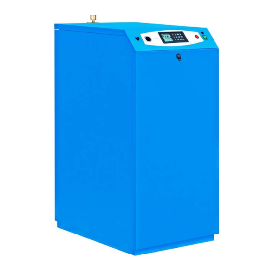
- Page 1 STREBEL S-AF Floor standing high efficiency boiler Installation & Maintenance Manual 2015-06-15 v1.0...
- Page 2 CONFORMITY The S - AF appliances comply with the following: • Gas directive 2009/142/EC • Efficiency Directive 92/42/EEC • Low voltage directive 2006/95/EC • Electromagnetic compatibility directive 2004/108/EC • Energy Efficiency ✫✫✫✫ • "Condensing" classification • NOx Class 5 (< 70 mg/kWh) For the serial number and year of manufacturer, refer to the technical data plate.
-
Page 3: Table Of Contents
INDEX SAFETY ............SAFETY WARNINGS AND REGULATIONS . -
Page 4: Safety Warnings And Regulations
SAFETY WARNINGS AND REGULATIONS • After unpacking the appliance, ensure that all parts are intact and complete as per the supply specifications, and if any non-conformities are found, contact the Representative that sold the appliance. • The appliance must be installed by professionally qualified personnel, in conformity with current national and local standards and the instructions in the manual supplied with the product. -
Page 5: Description
DESCRIPTION The aluminium heating units in the range S - AF are condensing heat generators, designed to heat rooms, and in combination with a storage tank, for the production of domestic hot water. They comprise: - an aluminium heat exchanger, with low water content and generously sized exchange surface to optimise energy efficiency and heating output;... -
Page 6: Identification
IDENTIFICATION The appliance is identified by means of: - the Technical data plate affixed to the casing. TYPE OF GAS AND BOILER BOILER MONTH AND YEAR OF SUPPLY PRESSURE CLASS CODE MANUFACTURE Bongioanni Caldaie S.r.l. Via Piave, n°14 12011 Borgo San Dalmazzo (CN) Italy Tel.+39.0171.687816 Fax.+39.0171.857008 BOILER MODEL... -
Page 7: Main Structure Components
MAIN STRUCTURE COMPONENTS 1 Front panel 2 Gas valve 3 Gas pressure switch 4 Syphon pressure switch 5 Water pressure sensor 6 Pressure gauge 7 Return sensor 8 System return manifold 9 Heating unit drain valve 10 Foot 11 Wheel 12 Condensate drain syphon 13 Condensate collection tank 14 Flue exhaust connector... -
Page 8: Technical Specifications
TECHNICAL SPECIFICATIONS S - AF DESCRIPTION Fuel G20 (20 mbar) - G31 (37 mbar) Country(s) of destination Appliance category II2H3P Type of appliance B23, B33, C43, C53, C63, C83 Max. nominal heating output (Qn) 113.0 150.0 200.0 235.0 275.0 Min. heating output (Qmin) 21.0 30.0 35.5... -
Page 9: Hydraulic Circuit - Sensors
HYDRAULIC CIRCUIT - SENSORS 1 Automatic purge valve 2 Supply sensor 3 Heat exchanger 4 Gas pressure switch 5 Pressure gauge connector 6 Return sensor 7 Water pressure sensor 8 Heating unit drain valve 9 Condensate drain syphon 10 Heat exchanger sensor 11 Safety thermostat 12 Flue exhaust sensor... -
Page 10: System Pump
SYSTEM PUMP Select a pump that is compatible with the hydraulic resistance of the heating unit and system. The graph shows the pressure drop curves of the heating units. 1300 1200 1100 1000 Flow rate (m3/h) It is recommended to observe the water flow rates in the table and as specified below. S - AF DESCRIPTION Water flow rate ΔT 20... -
Page 11: Control Panel
CONTROL PANEL Block indicator light due to intervention of safety devices DSP User interface with display Main switch with indicator light Main fuse (10A) Flame screen Heating safety thermostat with manual reset Fpc1 Primary pump 1 fuse (6.3A) Fpbl Storage tank pump fuse (6.3A) Fpc1 Fpc2 Primary pump 2 fuse (6.3A) Fpbl... - Page 12 menu Monday, 24. September 2012 09.37 DESCRIPTION OF SYMBOLS ON DISPLAY D.H.W. OPERATING MODE HEATING OUTSIDE OUTSIDE SENSOR HEATING TEMPERATURE REQUEST ACTIVE READING SUPPLY BOILER TEMPERATURE WATER PRESSURE READING SET DATE Monday, 24. September 2012 DOMESTIC HOT WATER SET TIME 09.37 REQUEST ACTIVE INITIAL SCREEN...
- Page 13 Description offunction Display OPERATING MODE SUMMER: DHW production only OUTSIDE ON OFF Monday, 24. September 2012 09.37 WINTER: heating only or heating and DHW OUTSIDE OUTSIDE Monday, 24. September 2012 Monday, 24. September 2012 09.37 09.37 NONE: no heating or DHW Anti-freeze or “Manual Test”...
- Page 14 Description offunction Display HOLIDAY Holiday start Holiday end 20 / 10 30 / 10 This enables entry of the holiday dates (start/end) 2012 2012 and values for the supply of domestic hot water and heating water during this period to confirm to confirm User menu User menu...
-
Page 15: Wiring Diagram
WIRING DIAGRAM Fuse Flue Damper Low voltage room thermostat Master Communication Slave Communication Pump Modulation Cascade Cascade Pump Remote Alarm Cascade Sensor (Sc) Outside Sensor Storage Tank Storage Tank Sensor (Sb) Thermostat Pump Modulation Fuse Relay 3 Boiler Pump 2 Storage Tank Fuse Pump... -
Page 16: Product Delivery
PRODUCT DELIVERY S - AF appliances are supplied in a single pack on a wooden pallet, protected by carton packaging and a wooden crate. The following material is supplied in a plastic envelope (A), placed inside the packaging: - Installation, operation and maintenance manual - Warranty certificate and adhesive labels with bar code - Hydraulic test certificate - Spare parts catalogue. -
Page 17: Handling
HANDLING After removing the packaging, the appliance is handled as follows: - Remove the front panel (1) to facilitate pick-up and handling. - Insert two 1” pipes (2) in the relative slots or insert the lift truck forks (3) under the structure. - Lift the unit and handle as required. -
Page 18: New Installations Or Replacements Of Older Appliances
NEW INSTALLATIONS OR REPLACEMENTS OF OLDER APPLIANCES When the appliance is installed on systems that are old or to be updated, ensure that: - The flue duct, if re-used, is suitable for the new condensing boiler, and that it is calculated and constructed in compliance with current standards, as straight as possible, airtight, insulated and free of any obstructions or narrowed sections. -
Page 19: Hydraulic Fittings
WARNINGS • Never soften water using the ion exchange principle. • Never fill the system using distilled or demineralised water, as these cause serious corrosion of the aluminium heat exchanger. The system must be filled and replenished with softened water to reduce overall hardness. The water must also be treated to maintain the pH factor within the envisaged range, to avoid the risk of corrosion. -
Page 20: Operating Principle Diagrams
OPERATING PRINCIPLE DIAGRAMS System Supply Example 1: Heating-only system System Return 1 Heating unit 7 Hydraulic separator 13 Check valve 2 Condensate drain syphon 8 Screening filter 14 Expansion vessel 3 Condensate neutraliser (*) 9 Shut-off valve 4 Drain 10 Supply manifold EAF Cold water inlet 5 ISPESL safety module 11 Return manifold... - Page 21 Example 3: System for the heating and production of DHW with storage tank upline of hydraulic separator WARNINGS • If the DHW is produced by the storage tank pump located upline of the hydraulic separator, use boiler pump 2 as the primary pump (without the mix valve).
-
Page 22: Electrical Connections
ELECTRICAL CONNECTIONS S - AF appliances require the connections shown below, which must be made by the installer or other professionally qualified personnel. To access the terminal board (MC): - Remove the front panel (1). - Insert the cables in the relative strain relief cable glands (2) located above the terminal board (MC) and route through the tube (3) on the inside of the casing. - Page 23 CONNECTIONS FOR OPERATION IN HEATING MODE AND DOMESTIC HOT WATER PRODUCTION WITH STORAGE TANK PUMP AND BOILER PUMP 2 (SYSTEM PUMP) (example 2 on page 20) 44 43 (12) (16) 0-10V PRmax ISPESL KIT Main Switch - - - - optional connections 230V~50Hz CONNECTIONS FOR OPERATION IN HEATING MODE AND DOMESTIC HOT WATER PRODUCTION WITH STORAGE TANK UPLINE OF THE HYDRAULIC SEPARATOR (example 3 on page 21)
-
Page 24: Connection Of Outside Sensor (Optional)
WARNINGS The following is compulsory: • Use of an omnipolar thermal magnetic circuit breaker, line disconnector, in compliance with EN standards. • Observance of the connections L (Phase) - N (Neutral). • Use of cable sections of at least 1 mm •... -
Page 25: Gas Connection
GAS CONNECTION Connection of the S - AF appliance to the gas mains must comply with current installation standards. S - AF Hydraulic fittings GAS Gas supply 1” 1/2 Ø 1088 1088 1088 Before making the connection, ensure that: - the type of gas corresponds to the design specifications of the appliance - the pipelines are thoroughly clean and free of processing residue. -
Page 26: Flue Exhaust And Extraction Of Combustion Air
FLUE EXHAUST AND EXTRACTION OF COMBUSTION AIR S - AF Dimensions Øi (internal) Øi “TYPE B” installations WARNINGS • S - AF appliances are equipped with a flue exhaust sensor, which in the event of anomalous increases in flue temperatures, shuts down the appliance. •... - Page 27 “TYPE C” installations S - AF appliances are approved for installation types “C43, C53, C63 and C83” and it is a COMPULSORY requirement that they are equipped with an exhaust flue and combustion air extractor in compliance with the above types of installation. WARNINGS •...
- Page 28 The heating appliance is delivered with the configuration B23. To intake air from the outside it is necessary to connect a plastic pipe with diameter of 100mm to the appliance intake outlet, bearing in mind that this pipe must not allow pressure drops over the value specified in the table below. The air inlet and flue outlet must be located in an area with the same pressure values.
-
Page 29: Condensate Removal
CONDENSATE REMOVAL WARNINGS • The condensate drain line must be tightly sealed, with dimensions suited to those of the syphon and without any throttled or reduced sections in gradient “i”, which is recommended at ≥ 3%. • The condensate drain must comply with current local and/or national standards. • Before commissioning the appliance, fill the syphon with water. i ≥ 3% boiler condensate flue condensate DRAIN The following is recommended: - Plumbing in manifolds on the condensate drain and flue exhaust - Installing a neutralisation device, such as the model supplied separately on request (code no. -
Page 30: System Filling And Draining
SYSTEM FILLING AND DRAINING S - AF appliances are NOT fitted with a filler valve, and therefore a suitable filling system must be envisaged during installation at the most convenient point for the installer. As a guideline, the figure illustrates a possible system filling unit connection point (CI). -
Page 31: Menu Navigation Trees And Procedure
MENU NAVIGATION TREES AND PROCEDURE Navigation procedure The appliance is supplied in the configuration STAND-BY. To scroll through the screen menus, use the keys shown in the diagram below. MENU User menu OUTSIDE USER OFF OFF 1. HEATING date NAVIGATION 2. - Page 32 User MENU navigation tree MENU User menu USER 1. HEATING NAVIGATION 2. DOMESTIC HOT WATER TREE TECHNICIAN 3. HOLIDAY 4. MAINTENANCE 5. SETTINGS 6. DIAGNOSTICS to confirm User menu 1. HEATING 2. DOMESTIC HOT WATER 3. HOLIDAY 4. MAINTENANCE 5. SETTINGS 6.
-
Page 33: Key To The User Menu Lines
Factory USER MENU Sub-menu Lines Field Keys Keys Keys settings English / 5. SETTINGS 1. Select Language English / Italiano Italiano Italiano Fahrenheit / 2. Select Units Fahrenheit / Celsius Celsius Celsius ---> ---> 3. Set date day / month / year 4. -
Page 34: Technician Menu Navigation Tree
Ref. menu Line title Meaning line 5. SETTINGS Select Language Selection of language (English or Italian) Select Units Selection of units of measurement (Celsius or Fahrenheit) Set date Entry or modification of current date Set time Selection of 12 or 24 hour format - Entry or modification of current time Restore factory settings Restores factory settings 6. - Page 35 Factory TECHNICIAN MENU Keys Sub-menu Lines Field Keys Keys settings 1. ADVANCED CH 1. Maximum power 100% 100% 0 - 100% SETTINGS 1. CH power set 2. Minimum power 0% 0 - 100% 1. ABS max temperature 80°C 20 - 85°C 2.
- Page 36 Factory TECHNICIAN MENU Keys Sub-menu Lines Field Keys Keys settings 3. SYSTEM SETTINGS 1.Ignition power 0-100% 2.Delay siphon check 0-60s Pump and 3.Number of boiler pump Two pumps 3-way valve / Double pump 4.Pump speed max 100% 15-100% 5.Pump speed min 15-100% 1.Boiler parameters Enabled/...
- Page 37 TECHNICIAN Factory Sub-menu Sub-menu Lines Field Keys Keys Keys Keys MENU settings 5. USER 1. DHW setpoint 75°C 20 - 85°C SETTINGS 1. DHW setpoint 2. Outside OFF / temperature for 7 - 25°C CH off 2. ECO setpoint 1. Heating --->...
- Page 38 TECHNICIAN Factory Sub-menu Sub-menu Lines Field Keys Keys Keys Keys MENU settings 7. RESTORE To restore the factory settings FACTORY SETTINGS ---> 8. BOILER TYPE 1. 60kW ---> 1. G20 2. 100kW ---> 3. 115kW 1. Wall Hung Boiler ---> 1.
-
Page 39: Key To Technician Menu
KEY TO TECHNICIAN MENU Ref. menu Line title Meaning line 1. ADVANCED CH SETTINGS 1.1.1. Maximum power Entry of maximum applicable power 1.1.2. Minimum power Entry of minimum applicable power 1.2.1 ABS max temperature Setting of maximum admissible appliance supply temperature 1.2.2 CH maximum setpoint Setting of maximum supply temperature, corresponding to minimum outside temperature... - Page 40 Ref. menu Line title Meaning line 3.1.4 Pump speed max Maximum boiler pump speed (primary) 3.1.5 Pump speed min Minimum boiler pump speed (primary) 3.1.6 Antilegionella Enables/Disables Anti-legionella function 3.1.7 Heat exchanger protection Enables/Disables protection with heat exchanger sensor Entry of increment from supply temp., over which the heat exchanger temp. generates 3.1.8 Heat exchanger delta an error...
- Page 41 Ref. menu Line title Meaning line 6. CASCADE 6.1.1 Cascade switch delay Interval between ignition of different boilers 6.1.2 Cascade min power Minimum available power in cascade 6.1.3 Single burner power Maximum power of single burner 6.1.4 Boiler for DHW Number of boilers also used for DHW 6.1.5 PI loop period...
-
Page 42: Initial Commissioning
INITIAL COMMISSIONING PRELIMINARY PROCEDURES The S - AF heating appliances leave the factory in the following condition: - set up for operation with G20 (natural gas), but with the option of operating with G31 (propane) - unit DSP in stand-by - in the “none”... -
Page 43: User Interface Settings Via Technician Menu
USER INTERFACE SETTINGS VIA TECHNICIAN MENU This procedure enables the user to check or modify the LANGUAGE THE CURRENT UNIT OF MEASUREMENT and the current date and time. Key to Description Display press MENU to display the MENU screens USER OUTSIDE OFF OFF to enter the TECHNICIAN menu, which requires... - Page 44 Key to Description Display press to select "2. Select Units" User interface settings Select Units 1. Select Language Fahrenheit 2. Select Units Celsius to confirm and access the selected line 3. Set date 4. Set time to modify the unit of measurement to be used to confirm to confirm to confirm the selection and return to line “2.
-
Page 45: Checking / Modifying Factory Settings
Key to Description Display press User interface settings Select time format to select "4. Set time" 1. Select Language 24 hours 2. Select Units 12 hours 3. Set date 4. Set time to confirm and access the selected line to confirm to confirm Set time to modify the time format used... -
Page 46: Change Of Gas Type
CHANGE OF GAS TYPE The appliance leaves the factory set to operate with G20. If using LPG proceed as described below. Key to Description Display press MENU to display the MENU screens USER OUTSIDE OFF OFF TECHNICIAN to enter the TECHNICIAN menu, which requires entry of the PASSWORD date time... -
Page 47: Heating Unit Ignition
Key to Description Display press Restore factory data to select the output corresponding to the appliance 1. 115kW model 2. 150kW 3. 200kW PLEASE WAIT 4. 240kW 5. 280kW to confirm the selection and return to the INITIAL screen. to confirm to confirm The setting of the “gas change”... - Page 48 Key to Description Display press To enter the PASSWORD “231”: Technician menu to enter the first digit “2” TWICE Insert code 2 3 1 to confirm and move to the second digit to select to confirm to enter the second digit “3” 3 TIMES to confirm and move to the third digit Technician menu...
-
Page 49: Errors With Safety Block
In the event of a malfunction, the appliance applies a Safety block or Safety stop, depending on the type of error/fault that has occurred, as signalled on the DSP display. Error message Errors with safety block The table below lists the errors/faults that generate a Safety Block. DHW sensor open To restore normal operating conditions: ERROR 33... -
Page 50: Operational Checks - Calibration After Gas Type Changes
Display items Meaning The flue sensor has detected a temperature Flue sensor open Error 46 outside the admissible range (equivalent to short circuit) Water pressure error Error 47 The water pressure switch is disconnected or damaged Gas pressure Error 76 Low gas pressure (pressure switch tripped) Syphon error Error 77... - Page 51 If these do not correspond, gradually adjust the MAX gas adjuster screw on the gas valve until the analyser shows the correct combustion values. S - AF gas valve S - AF gas valve 115 / 150 200 / 240 / 280 - Press to reduce power to 0% (see section "MANUAL TEST function"...
-
Page 52: Outside Sensor And Climatic Curve
OUTSIDE SENSOR AND CLIMATIC CURVE When operation envisages the use of the outside sensor ("sliding temperature") the MAXIMUM and MINIMUM SUPPLY temperatures must be set, as well as the OUTSIDE temperature range so that the appliance can calculate the climatic curve on the basis of these settings. -
Page 53: 0..10V Input Check
0..10V INPUT CHECK IMPORTANT PRELIMINARY INFORMATION When an external controller is used with a 0-10V signal for power control, it is essential that the system, on the supply side, is fitted with an additional temperature sensor, to be connected to the external controller. This must therefore be installed if not already present. -
Page 54: Dhw Request Type
DHW REQUEST TYPE Depending on the selected device used (parameter Heating 1.6), the following table shows the priorities according to the conditions of the room thermostat and Scheduler settings. CH Demand Only OTC Room thermostat 0-10V (power or temperature) The heating unit follows the Scheduler settings, observ- ing the bands set as ON, The heating unit follows... -
Page 55: Scheduler Settings
SCHEDULER SETTINGS The system also envisages the option of setting time bands during which the heating unit is set to operate, if there is a demand for heat, and those during which it remains off, or in ECO mode when fitted with an outside sensor. There is a maximum of 6 programmable time bands within 24 hours, each of which must be identified by a start time (ON), and end time (OFF). - Page 56 Key to Description Display press Scheduler set Monday-Friday 1. --:-- - --:-- to select the single day or group of days in the week 5. Friday 2. --:-- - --:-- 6. Saturday 3. --:-- - --:-- 7. Sunday 4. --:-- - --:-- 8.
-
Page 57: Temporary Shutdown Or Holiday Schedule
TEMPORARY SHUTDOWN OR HOLIDAY SCHEDULE This function enables a reduction in the operating regime of the heating unit in the case of temporary absences, weekends, holidays and above all automatic restart after the set time interval. WARNINGS • During the holiday period, it is essential to leave the electrical and gas mains supplies to the appliance powered, to ensure correct operation. - Page 58 Key to Description Display press Holiday start to return to the initial screen 20 / 10 2012 OUTSIDE OFF OFF to display the “Holiday start” date date to confirm time to set the holiday start day Holiday start Holiday start 30 / 10 30 / 10 2012...
-
Page 59: Maintenance And Cleaning
MAINTENANCE AND CLEANING Periodic maintenance is a compulsory legal requirement and is essential to ensure optimal safety, performance and lifetime of the appliance. Internal cleaning of the appliance and removal of combustion residue from the exchange surfaces are operations required at least once a year. - Page 60 Burner disassembly and cleaning If appliance performance indicates the need to clean the burner head, proceed as follows: - Remove the two connectors of the blower and that of the gas valve - Unscrew the three-part fitting (4) of the gas line - Loosen the four fixing screws (5) and remove the burner- blower-gas valve assembly (6) from the heat exchanger, taking care not to damage the seal (7)
-
Page 61: Troubleshooting
Electrode disassembly and replacement WARNINGS • During disassembly of the electrodes, take care not to damage the seals (18) and (19). If damaged, replace immediately. - Loosen the fixing screws of the electrode unit (20), remove and check to ensure good working condition. REPLACEMENT of the electrodes is recommended given the frequent ignition of the appliance. - Page 62 Fault Cause Remedy - Presence of air in the system - Purge the system generator reaches temperature but the heating systems - Unblock the pump - System pump are cool - Replace the pump - System safety valve - Check setting or efficiency - Check filling pressure Frequent intervention of the system - System pressure...
- Page 63 NOTES - 63...
- Page 64 Strebel Ltd 1f Albany Park Industrial Estate, Frimley Road, Camberley, Surrey, GU16 7PB Tel: 01276 685422 Fax: 01276 685405 Email: info@strebel.co.uk Web: www.strebel.co.uk Further information on our complete product range is available from our website. CAST IRON – CONDENSING – STEEL SHELL – WATER HEATERS – RENEWABLES...
Need help?
Do you have a question about the S-AF and is the answer not in the manual?
Questions and answers