
Subscribe to Our Youtube Channel
Related Manuals for Extech Instruments SD910


Summary of Contents for Extech Instruments SD910
- Page 1 Distributore Autorizzato : Geass S.r.l. - Torino - Tel.: +39 011.22.91.578 - info@geass.com - web site :www.geass.com USER MANUAL 3‐Channel DC Voltage Datalogger Model SD910 ...
-
Page 2: Table Of Contents
1. INTRODUCTION 3 2. DESCRIPTIONS 4 3. OPERATION 5 Power Connecting Voltage Cables Datalogging Time/Date/Sample Rate Check SD Card Data Structure Transferring Data to a PC Advanced Settings System RESET RS232 Interface Backlight 4. MAINTENANCE 8 Battery Replacement Cleaning and Storage 5. SPECIFICATIONS 9 SD910‐en‐GB_V1.2 9/16... -
Page 3: Introduction
1. Introduction Thank you for selecting the Extech SD910 3-Channel Voltage Datalogger. The SD910 is a three channel 0 to 300mV or 0 to 3000mV DC voltage monitor and data logger. Data is stored at a selectable rate and stored for easy export to a spreadsheet. This device is shipped fully tested and calibrated and, with proper use, will provide years of reliable service. Please visit our website (www.extech.com) to check for the latest version of this User Guide, Product Updates, Product Registration, and Customer Support. Features Triple LCD simultaneously displays (3) 300mV or (3) 3000mV channels Datalogger date/time stamps and stores readings on an SD card in Excel® format for easy transfer to a PC Selectable data sampling rate: 1, 2, 5, 10, 30, 60, 120, 300, 600 seconds, auto SD910‐en‐GB_V1.2 9/16... -
Page 4: Descriptions
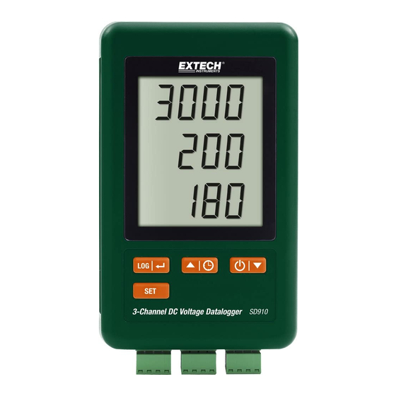
Channel 1 Display Channel 2 Display Channel 3 Display LOG and (ENTER) button SET button ▲and (TIME) button ▼ and ( Power) button AC adaptor socket Reset button 10. RS‐232 output 11. SD memory card socket 12. Channel 1 input 13. Channel 2 input 14. Channel 3 input Note: Battery Compartment and Tilt Stand are located on the back of the meter. SD910‐en‐GB_V1.2 9/16... -
Page 5: Operation
When the icon appears in the display the batteries are weak and should be replaced. However, in‐spec. measurements may still be made for several hours, after the low battery indicator appears. Connecting Voltage Cables Connect the voltage wires to the plug as shown and then insert the plug into the sockets on the bottom of the datalogger (observe polarity) Up to three cables may be installed. The voltage for the inserted cables will be displayed 1, 2, and 3 from top to bottom. 0.00 will be displayed for open or unused inputs. Datalogging Open the left side door and insert a formatted SD card Notes The SD card should be 1GB to 4GB in capacity. Do not use memory cards formatted by other meters or cameras. Use the SD card formatting procedure under the advanced features section of this manual to correctly format the card. The internal clock must be set to the correct time. See the advanced features section of this manual to set the clock. The default data structure uses a decimal point “.” as the numeric decimal indicator. See the advanced features section of this manual to change this to a comma “,”. If the SD memory card is not installed, “EMPTY” will appear in the display. If the voltage cable is not installed, random numbers may appear in the data file. If the voltage cable is not installed, after data download the e units symbol may not appear in the display. SD910‐en‐GB_V1.2 9/16... -
Page 6: Time/Date/Sample Rate Check
Displayed error messages: CArd The memory card is full or there is a problem with the card LobAt The battery is low and datalogging is disabled CArd The SD card is not inserted Press the LOG button for >2 seconds to begin logging. “DATALOGGER” will appear in the display and the meter will beep each time the data is recorded (if the beeper is enabled). To stop datalogging, press the LOG button for >2 seconds. “DATALOGGER” will change to “DATA” and the meter will count down through the recorded data. NOTE: To avoid corrupting data, do not remove the memory card without properly ending the record function. Time/Date/Sample Rate Check Press and Hold the button for >2 seconds and the display will cycle through the date, time and sample rate information. SD Card Data Structure When the SD card if first inserted into the datalogger the folder MVA01 is created. The first datalogging session will then create a file MVA01001.XLS. All data will be saved to this file until the number of columns reaches 30,000. After 30, 000 columns a new file, MVA01002.XLS is created. This is repeated every 30,000 columns until MVA01099.XLS. At this point a new folder, MVA02 is created and the process is repeated. MVA10 is the final folder. Transferring Data to a PC Remove the memory card from the datalogger and plug it into the SD card slot on the PC. Launch Excel and open the data file on the memory card. The file will appear similar to the figure below. SD910‐en‐GB_V1.2 9/16... -
Page 7: Advanced Settings
Set the RS232 data output ON/OFF Set the voltage range to 300mV or 3000mV Press and Hold the SET button for >2 seconds to enter the setting mode. The first function (Sd F) will appear in the display. Press the SET button to step through the seven functions. Use the ▲ and ▼ buttons to adjust the selected function. Use the “LOG” button to step through fields within a function. In the SET mode, if no button is pressed within 5 seconds, the logger will revert back to the standard mode. Sd F – Format the SD card. Press the ▲ button to select yES or no. For yES, press the button. When yES and Ent appear, press the key again to format the card and erase all existing data. The screen will display a flashing yEs and ESC while the memory is being erased and formatted. dAtE – Set the date and time. Press the ▲ or ▼ buttons to adjust the selected (blinking) field. Press the button to store the value and to step through the various fields (Year, Month, Day, Hour, Minute, Second) SP‐t – Set the sample rate. Press the ▲ button to select the desired sample rate and press Enter to store the selection. The selections are: 5, 10, 30, 60, 120, 300, 600 seconds and AUTO. In AUTO, the data will be stored every time there is a change of >10 digits. bEEP ‐ Set the beeper ON or OFF. Press the ▲ button to select ON or OFF and press to store the selection. dEC ‐ Set the SD card Decimal character. Press the ▲ button to select USA (decimal) or Euro (comma) and press to store the selection. rS232 ‐ Set the RS232 data output ON/OFF. Press the ▲ button to select ON or off and press to store the selection. Rng – Set the voltage range Press the ▲ button to select either to 3000mV or the 300.0mV range and press to store the selection. ESC – Exit the setting mode. Press the SET button to return to normal operation. SD910‐en‐GB_V1.2 9/16... -
Page 8: System Reset
System RESET If a condition appears where the CPU does not respond to keystrokes or the meter seems frozen, press the RESET button on the side of the datalogger (use a paper clip or similar pointed object) to return the meter to a working state. RS232 Interface For streaming of data to a PC via the RS232 Output jack, the optional 407001‐USB kit (RS232 to USB cable and driver CD) along with the 407001 software (available free at www.extech.com) are required. Backlight Press the button to turn on the backlight. The backlight will auto turn off after 5 seconds. 4. Maintenance Battery Replacement To replace or install batteries, remove the Philips head screw that secures the rear battery cover and lift off the cover. Replace the six AAA batteries (use alkaline heavy duty type), observing polarity. Replace and secure the cover. Battery Safety Notes: Please dispose of batteries responsibly; never dispose of batteries in a fire, batteries may explode or leak. If the meter is not to be used for 60 days or more, remove the battery and store separately. Do not mix battery types or freshness levels; please use batteries of the same type and of the same freshness level. Never dispose of used batteries or rechargeable batteries in household waste. As consumers, users are legally required to take used batteries to appropriate collection sites, the retail store where the batteries were purchased, or wherever batteries are sold. Disposal: Do not dispose of this instrument in household waste. The user is obligated to take end‐of‐life devices to a designated collection point for the disposal of electrical and electronic equipment. Cleaning and Storage Periodically wipe the case with a damp cloth and mild detergent; do not use abrasives or solvents. Please remove the batteries if the meter is stored for a long period of time. SD910‐en‐GB_V1.2 9/16... -
Page 9: Specifications
Input impedance 5.6MOhms Inputs Negative (‐) terminals connected to analog ground Datalogger Sampling Time 1/2/5/10/30/60/120/300/600 seconds/auto (with the sampling rate set to ‘1’ second some data points could be lost) Data error number ≤ 0.1% no. of total saved data typically Display update rate Approx. 1 second Data Output RS 232 Operating Temperature 0 to 50 °C (32 to 122°F) Operating Humidity < 85% R.H. Power Supply 9V AC adaptor required for datalogging 6 AAA (UM4) Alkaline or heavy duty 1.5 V batteries are used for clock backup and measurement display only. Battery life Dependent on sample rate, for new alkaline batteries and 60 second sampling time, > one month is typical. Fast sample rates will significantly reduce battery life. The battery life will decrease if the beeper is set ON Weight 199 g (0.44 lbs.) Dimension 132 x 80 x 32 mm (5.2 x 3.1 x 1.3“) Note: Above specification tests performed under environmental RF Field Strength < 3 V/M & frequency < 30 MHz only. Copyright © 2015‐2016 FLIR Systems, Inc. All rights reserved including the right of reproduction in whole or in part in any form ISO‐9001 Certified www.extech.com SD910‐en‐GB_V1.2 9/16...
Need help?
Do you have a question about the SD910 and is the answer not in the manual?
Questions and answers