emz smart Sol Operating Instructions Manual
Hide thumbs
Also See for smart Sol:
- Assembly and operating instructions manual (92 pages) ,
- Assembly & operation (104 pages)

Subscribe to Our Youtube Channel
Related Manuals for emz smart Sol


Summary of Contents for emz smart Sol
- Page 1 COMFORT OPERATING INSTRUCTIONS DIFFERENTIAL TEMPERATURE CONTROLLER FOR MEDIUM-SIZED SOLAR THERMAL PLANTS USED FOR HEATING DOMESTIC WATER AND SUPPORTING THE HEATING SYSTEM.
- Page 2 Non-authorized disclosure, reproduction, divulgation or editing of this documentation, as well as exploitation, utilization or publication, are prohibited. The rights to the word and design marks ›emz - smart solutions‹ and ›smart Sol‹ are the exclusive property of emz-Hanauer GmbH & Co.KGaA.
-
Page 3: Table Of Contents
TABLE OF CONTENTS Page 3 Table of contents Page Important fundamental information Symbols used Description Dimensions Technical Data Designation of the components Operation of the controller Display Opening the terminal cover Wall-mounting Connection to power supply Hydraulic systems Functions for boiler control Thermostat functions Commissioning mode Automatic mode... -
Page 4: Important Fundamental Information
Important! The fitter installing the controller must inform the plant operator about operation, functioning and the method of action of the smart Sol! Keep these Assembly and Operating Instructions and all reference documents so that they are available if required. -
Page 5: Symbols Used
SYMBOLS USED Page 5 When handling the differential temperature controller smart Sol and the entire plant, please make sure that the following safety provisions in the Assembly and Operating Instructions are complied with! Danger! Immediate danger for assets, life and limb! -
Page 6: Description
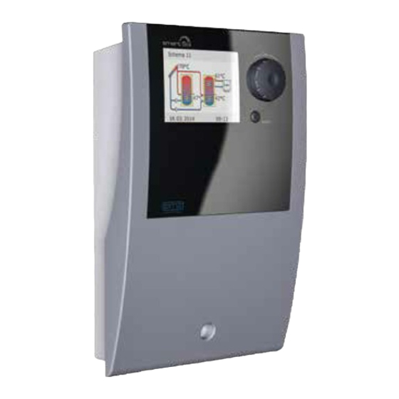
Page 6 DESCRIPTION The differential temperature controller smart Sol is an independent electronic controller for surface-mounting which is used for the control of solar thermal plants. The controller is equipped with a robust three-part plastic housing which can only be opened by means of tools (screw driver PH2). -
Page 7: Dimensions
DIMENSIONS Page 7 115 mm 46 mm 5mm/9mm 26 mm 57,5 mm 57,5 mm 173 mm 120 mm 5 mm 27 mm... -
Page 8: Technical Data
The fitter explains all the relevant functions to the operator. For operation, it is essential that the housing is closed and free of damage. Scope of supplies 1 Differential temperature controller smart Sol 1 Instruction manual Differential temperature controller smart Sol... - Page 9 TECHNICAL DATA Page 9 Max. cross sections to be connected Cable end sleeve: 0.25 to 0.75 mm Single-wire 0.50 to 1.50 mm Fine-wired 0.75 to 1.50 mm Interfaces TS1 / TS2 / TS3 / TS4 Design 2 spring-type terminals each Assignment as inputs Admissible temperature probe Temperature sensor Pt 1000...
-
Page 10: Designation Of The Components
Page 10 DESIGNATION OF THE COMPONENTS Rotary encoder with OK button Display esc button Housing cover Housing base Spare fuse Fuse Terminals Break-out segments Screw connection strain relief device Strain relief device Drillhole for securing bolt Screw fastening of terminal cover Terminal cover... -
Page 11: Operation Of The Controller
Page 11 The entire set-up and operation of the differential temperature controller smart Sol is effected via only two control elements on the device front. All settings and interrogations are effected via the rotary encoder. To find a required menu item, turn the rotary encoder to ›scroll‹... -
Page 12: Display
For indication of the operating mode and for communication in case of set-up, malfunction, modification and evaluation, the differential temperature controller smart Sol is equipped with a coloured full graphics display which is permanently backlit. The display is active as long as there is supply voltage on the controller. -
Page 13: Opening The Terminal Cover
OPENING THE TERMINAL COVER Page 13 Danger! Mortal danger due to electrocution! Whenever work is performed on the open terminal cover, all poles of the power supply must be disconnected reliably and protected against being switched on again! Release the lock screw. Swing terminal cover forward ... -
Page 14: Wall-Mounting
Page 14 WALL-MOUNTING Important! The device corresponds to protection type IP 20 - make sure the appropriate prerequisites exist on the envisaged place of installation. Do not use the housing base as drill template. A device with damaged housing must not be operated! Fasten the top securing bolt so that a space of 2 to 3 mm is created between the wall and... -
Page 15: Connection To Power Supply
The differential temperature controller smart Sol is connected to the power supply via three groups of spring-type terminals which are visible once the terminal cover is opened. - Page 16 Page 16 CONNECTION TO POWER SUPPLY Connection of a switching valve to RO1/RO2 Connection diagram for a switching Connection diagram for a switching valve without power supply to RO2: valve with power supply to RO2: L‘ Valve Valve Connection of a switching valve to REL Connection diagram for a switching Connection diagram for a switching valve without power supply to REL:...
- Page 17 CONNECTION TO POWER SUPPLY Page 17 Volumetric flow sensor: Measurement of solar radiation (heat quantity): The solar yield is calculated from the flow rate and the differential temperature. The differential temperature is the difference in the temperature of the collector sensor and the solar circuit return line sensor.
- Page 18 Page 18 CONNECTION TO POWER SUPPLY Important! Depending on whether HE pumps are used as solar or heating pumps, they are supplied with proportional or inverted control signals. (Both analogue and PWM control.) 10V analog/ 100% PWM 9-10 mm The strain relief device can only ensure solid clamping if the cables are not stripped to a length of over 35 mm.
- Page 19 Page 19...
-
Page 20: Hydraulic Systems
If you want to complete an existing system or replace the existing controller, please make sure that smart Sol is compatible with the existing configuration! The sensors are connected to TS1 to TS4, the order not being significant; pumps and valves are connected to RO1 / RO2 - The interfaces are assigned to the functions in question on commissioning. - Page 21 Page 21 HYDRAULIC SYSTEM 1 Collector sensor 1 Tank 1 Solar circuit pump 1 Tank sensor 1, bottom Connection to Collector sensor 1 power supply Solar circuit pump 1 Tank sensor 1, bottom...
- Page 22 Page 22 HYDRAULIC SYSTEM 2 Collector sensor 1 Tank sensor 1, Tank 1 Solar circuit pump 1 Tank sensor 1, bottom Connection to Collector sensor 1 power supply heating boiler con- nection according to Solar circuit pump 1 Tank sensor 1, bottom page 45-46 Tank sensor 1, top...
- Page 23 HYDRAULIC SYSTEM 3 Page 23 Collector sensor 1 Charging area valve Tank sensor 1, Solar Tank 1 circuit pump 1 Tank sensor 1, bottom Connection to Collector sensor 1 power supply Solar circuit pump 1 Tank sensor 1, bottom Tank sensor 1, top Charging area valve...
- Page 24 Page 24 HYDRAULIC SYSTEM 4 Collector sensor 1 Tank sensor 1, Solar Tank 1 circuit pump 1 Tank sensor 1, bottom Charging area valve Connection to Collector sensor 1 power supply Solar circuit pump 1 Tank sensor 1, bottom Tank sensor 1, top Charging area valve...
- Page 25 HYDRAULIC SYSTEM 5 Page 25 Collector sensor 1 Heat exchanger sensor Solar circuit Tank 1 pump 1 Heat exchanger Tank pump sensor 1, bottom Connection to Collector sensor 1 power supply Solar circuit pump 1 Tank sensor 1, bottom Heat exchanger sensor Heat exchanger pump...
- Page 26 Page 26 HYDRAULIC SYSTEM 6 Collector sensor 1 Tank sensor 1, Heat exchanger sensor Solar circuit Tank 1 pump 1 Heat exchanger Tank pump sensor 1, bottom Connection to Collector sensor 1 power supply heating boiler con- nection according to Solar circuit pump 1 Tank sensor 1, bottom page 45-46...
- Page 27 HYDRAULIC SYSTEM 7 Page 27 Collector sensor 1 Bypass sensor Tank 1 Solar circuit pump 1 Tank sensor 1, bottom Bypass valve Connection to Collector sensor 1 power supply Solar circuit pump 1 Tank sensor 1, bottom Bypass sensor Bypass valve...
- Page 28 Page 28 HYDRAULIC SYSTEM 8 Collector sensor 1 Tank sensor 1, Bypass sensor Tank 1 Solar circuit pump 1 Tank sensor 1, bottom Bypass valve Connection to Collector sensor 1 power supply heating boiler con- nection according to Solar circuit pump 1 Tank sensor 1, bottom page 45-46 Tank sensor 1, top...
- Page 29 HYDRAULIC SYSTEM 9 Page 29 Collector sensor 1 Tank sensor 1, Transfer pump Tank 1 Tank 2 Solar circuit pump 1 Tank Tank sensor 2, sensor 1, bottom bottom Connection to Collector sensor 1 power supply Solar circuit pump 1 Tank sensor 1, bottom Tank sensor 1, top Transfer pump...
- Page 30 Page 30 HYDRAULIC SYSTEM 10 Collector sensor 1 Tank 1 Tank 2 Solar circuit pump 1 Tank Tank sensor 1, sensor 2, bottom bottom Note: Priority charging has been set to T2 in the factory. Solar circuit pump 2 Connection to Collector sensor 1 power supply Solar circuit pump 1...
- Page 31 HYDRAULIC SYSTEM 11 Page 31 Collector sensor 1 Tank sensor 2, Tank 1 Tank 2 Solar circuit pump 1 Tank Tank sensor 1, sensor 2, bottom bottom Note: Priority charging has been set to T2 in the factory. Solar circuit pump 2 Connection to Collector sensor 1 power supply...
- Page 32 Page 32 HYDRAULIC SYSTEM 12 Collector sensor 1 Tank 1 Tank 2 Tank Tank Solar circuit sensor 1, sensor 2, pump 1 bottom bottom Note: Priority charging has Tank switching valve 1 been set to T2 in the factory. Connection to Collector sensor 1 power supply Solar circuit pump 1...
- Page 33 HYDRAULIC SYSTEM 13 Page 33 Collector sensor 1 Tank sensor 2, Tank 1 Tank 2 Tank Tank Solar circuit sensor 1, sensor 2, pump 1 bottom bottom Note: Priority charging has Tank switching valve 1 been set to T2 in the factory. Connection to Collector sensor 1 power supply...
- Page 34 Page 34 HYDRAULIC SYSTEM 14 Collector Collector sensor 1 sensor 2 Tank 1 Tank Solar circuit Solar circuit sensor 1, pump 1 pump 2 bottom Connection to Collector sensor 1 power supply Solar circuit pump 1 Tank sensor 1, bottom Collector sensor 2 Solar circuit pump 2...
- Page 35 HYDRAULIC SYSTEM 15 Page 35 Collector Collector sensor 1 sensor 2 Tank sensor 1, top Tank 1 Tank Solar circuit Solar circuit sensor 1, pump 1 pump 2 bottom Connection to Collector sensor 1 power supply heating boiler con- nection according to Solar circuit pump 1 Tank sensor 1, bottom page 45-46...
- Page 36 Page 36 HYDRAULIC SYSTEM 16 Note: Heating return tempera- Collector sensor 1 ture increase only possible at the REL output! Tank sensor 1, top Tank sensor 1, Solar Tank 1 bottom circuit pump 1 Return line sensor Three-way valve, return temperature increase Connection to Collector sensor 1...
- Page 37 HYDRAULIC SYSTEM 17 Page 37 1 Collector sensor 2 Heat Swimming exchanger pool sensor sensor Solar circuit pump 1 Heat exchanger pump Collector rever- sing valve Collector sensor 1 Connection to power supply Collector reversing valve Heat exchanger sensor Solar circuit pump 1 Connection according to page 16 Swimming pool sensor...
- Page 38 Page 38 HYDRAULIC SYSTEM 18 1 Collector sensor 2 Heat Swimming exchanger pool sensor sensor Solar circuit Solar circuit pump 1 pump 2 Heat exchanger pump Collector sensor 1 Connection to power supply Heat exchanger pump Connection according Heat exchanger sensor Solar circuit pump 1 to page 16 Attention !
- Page 39 HYDRAULIC SYSTEM 19 Page 39 Collector sensor Heat Swimming exchanger pool sensor sensor Tank sensor 1, Tank 1 bottom Solar circuit pump 2 Heat exchanger pump Solar circuit pump 1 Note: Priority charging has been set to T1 in the factory. Collector sensor 1 Connection to power supply...
- Page 40 Page 40 HYDRAULIC SYSTEM 20 Collector sensor Heat Swimming exchanger pool sensor sensor Tank sensor 1, Tank 1 bottom Solar circuit pump 1 Accumulator re- Heat exchanger pump versing valve 1 Note: Priority charging has been set to T1 in the factory. Collector sensor 1 Connection to power supply...
-
Page 41: Functions For Boiler Control
FUNCTIONS FOR BOILER CONTROL Page 41 The functions for boiler control are accomplished via the potential-free relay contact which is connected accordingly to the relevant interface of the heating boiler. The individual functions are assigned the following priorities: Anti-legionella priority 1 11 14 12 recharge suppression priority 2... - Page 42 FUNCTIONS FOR BOILER CONTROL Page 42 Disable recharge The efficiency of a solar plant increases as the recharge of the tank from the boiler decreases. Consequently, „disable recharge“ means that recharging of the water tank is blocked by the boiler. Recharge suppression during solar yield The recharge function of the heating boiler is suppressed while a solar circuit pump is operating.
- Page 43 FUNCTIONS FOR BOILER CONTROL Page 43 Note! For boilers without control input, the functions for boiler control can be accessed by the simulation of temperature values. To enable reheating or anti-legionella functions, the corresponding boiler temperature must be increased at the boiler control. The differential temperature controller smart Connection provided at the Sol regulates the boiler control functions by...
-
Page 44: Thermostat Functions
Page 44 THERMOSTAT FUNCTIONS The controller’s free outputs can be used as thermostats for various applications. Settings must be made to this effect in professional mode under ›1.3.1 Thermostat‹. Control signals can be defined as temperature thermostat, timer, timer thermostat or temperature comparator. T OFF T ON Temperature thermostat ›Heating‹:... -
Page 45: Commissioning Mode
Commissioning is communicated in plain text; the user must make a selection, acknowledge and - if applicable - jump to the next menu item. The differential temperature controller smart Sol accompanies you during the entire configuration and interrogates everything it must know for optimum operation. - Page 46 Page 46 COMMISSIONING MODE If you select „Choose system“, the graphic System 1 illustration of a hydraulic system is shown. Scroll through all available schemes using the rotary encoder, select the illustrated scheme by pressing the „OK“ button. Then, any parameters relevant for the se- lected scheme are queried.
- Page 47 COMMISSIONING MODE Page 47 0.3 Outputs Heat exchanger p Some other output assignments offer further HE control signal options: e.g. pumps may be specified as high- efficiency pumps. Runs with solar pump Specific options can be selected for individual assignments. 04.
- Page 48 Page 48 COMMISSIONING MODE 0.3 Outputs Solar pump 1 The HE control signal is specified as: analogue solar pump / PWM solar pump / analogue HE control signal heating pump / PWM heating pump / Wilo Solar pump - Analog Type ST25/7 PWM.
- Page 49 COMMISSIONING MODE Page 49 0.4 Inputs HE control signal Continue with „Sensors“ once all assigned inputs have been allocated. Sensor Next 04. 07. 2015 09:19 0.4.1 Volume flow Impeller 1 Heat quantities If the volume flow is measured with an impel- Next ler, „Impeller 1“...
- Page 50 Page 50 COMMISSIONING MODE 0.4.1 Volume flow Impeller 1 ... specify the unit as Imp/l or l/Imp as well Unit Imp/l as the corresponding factor with 1 to 100 Imp/l or 0.1 to 10.0 l/Imp. Select the cor- Pulses/litre 1Imp/l responding output.
- Page 51 COMMISSIONING MODE Page 51 1.1.4.1 Heat qty. 1 Activation Heat qty. After activation, the volume flow sensor as 0 kWh well as ... Volume flow Impeller 1 04. 07. 2015 09:23 1.1.4.1 Heat qty. 1 Ret.line sens. the return line sensor and the supply line sen- Supp.line sens.
- Page 52 Page 52 COMMISSIONING MODE 1.1.4 Heat quantities Heat qty. 2 The energy measured by the heat quantity counter is displayed in kWh or illustrated in a Diagram Week diagram. Heat qty. The illustration includes „Week“, „Month“ or „Year“. 0kWh By pressing the „Reset“ button, the heat Reset quantity counter is reset to 0.
- Page 53 COMMISSIONING MODE Page 53 System 1 All hydraulic schemes which are possible due to your input are displayed. Make your selection by scrolling with the ro- tary encoder and acknowledge with „OK“. 04. 07. 2015 09:24 0.7 Checklist Test outputs Holiday function „0.7 Checklist“...
- Page 54 Page 54 COMMISSIONING MODE Note! If the hydraulic installation does not comply with the standard, or if special products were used which cause incorrect valve positions during test operation, the „Inverted“ option must be activated by accessing the corresponding output menu 1.3.7 in professional mode after commis- sioning.
- Page 55 COMMISSIONING MODE Page 55 0.7 Checklist Test outputs Holiday function Next Complete the checklist by pressing „Next“. 04. 07. 2015 09:26 „0.8 Parameter“ appears 0.8 Parameter Setting the limit temperatures: T limit 1 60.0°C The tanks are only loaded until the maximum T max.tank 1 59.0°C temperature „T max.
- Page 56 Page 56 COMMISSIONING MODE Note! The antifreeze protection function of the controller may prevent the heating system from damage which could be caused by freezing medi- um. To this end, enter the lowest temperature „T ON“ at which a system filled with pure water without antifreeze could operate without suffering damage.
- Page 57 COMMISSIONING MODE Page 57 1.3.2 Tube collector Activation To receive correct measured values from the tube collector system, the pump Start time-dependent must be switched ON briefly. t-ON 10min By activation of the function, the solar circuit pump can be started T ON 20.0°C time- and/or temperature-controlled.
- Page 58 Page 58 COMMISSIONING MODE 1.3.10 Post Heatin... Here, reheating can be activated. Activation The boiler is defined as Boiler type ›Solid-fuel boiler‹ or ›Gas/oil‹. Solid fuel boiler In case of solid-fuel boilers reheating is made via the charge pump of the drinking water Hysteresis 10.0K tank and is only activated if the temperature...
- Page 59 COMMISSIONING MODE Page 59 1.3.10 Time block 1 Ref. temp. 45.0°C Each period can be defined with ›Saturday‹, Starting time 00:00 ›Sunday‹, ›Weekends‹, Monday - Sunday‹ or End time ›Monday - Friday‹. 23:59 Return to the post heating requirements by Time period pressing the „esc“...
-
Page 60: Automatic Mode
04. 07. 2015 09:30 Hinweis! Note! Kontrollieren Sie regelmäßig die Displayanzeige des smart Sol, Check the display screen of the smart Sol on a regular um eventuell auftretende Störungen zeitnah beheben zu können! basis to be able to eliminate any malfunctions promptly! - Page 61 Page 61...
-
Page 62: Operation Mode
Page 62 OPERATION MODE Note! The following illustration shows the structure of the control menu. The controller does not display any sub menus which are not required by either the selected scheme or by the activated options. 1 Main menu 1.1 Evaluation 1.1.1 Measured values 1.9 About... - Page 63 OPERATION MODE Page 63 System 1 On the controller, the user can make various settings and obtain information about states and processes. To this effect, press the button ›OK‹ in automatic mode. 04. 07. 2015 10:19 1 Main Menu Evaluation Settings ›1 Main menu‹...
- Page 64 Page 64 OPERATION MODE 1.1 Evaluation Measured values ...›1.1 Evaluation‹ appears. Service hours Another selection level appears. CO2 savings Once the first subitem Heat quantities ›Measured values‹ is selected, ... Message list 04. 07. 2015 10:20 1.1.1 Measured val..›1.1.1 Measured val...‹ appears. Coll 1 78.2°C Here, the temperatures and dates...
- Page 65 OPERATION MODE Page 65 ...›1.1.2 Service hours‹ appears. 1.1.2 Service hours The operating time of the activated plant Solar pump 1 112h components is displayed in hours. Solar pump 2 By actuating the menu item ›Reset‹, all counters are reset to zero. Reset The values are saved once per day, so that one day max.
- Page 66 Page 66 OPERATION MODE 1.1.4 Heat quantities ›1.1.4 Heat quantities‹ appears. Heat qty. 2 Up to two heat counters can be Diagram Week configured for the collection of Heat qty. (calc.) the generated energy quantity. The evaluation period can be selected via 108kWh the ›Diagram‹...
- Page 67 OPERATION MODE Page 67 1.1.4.1 heat qty. 1 Return line sensor Return and feed sensors are assigned. Supply line sensor The filling can be defined as water, Tyfocor, propylene glycol or ethylene glycol. Glycol type ›Efficient tank-charge‹ defines Water whether this heat quantity is used for efficient buffer charge.
- Page 68 Page 68 OPERATION MODE 1.10 Message list M05: ... the error message appears in plain text. Sensor short-circuit If necessary, take the appropriate measures. on TS3! Return to ›1 Main menu‹. Press ESC to return Continue with ›Settings‹. 04. 07. 2015 10:22 1.2 Settings Date/Time...
- Page 69 OPERATION MODE Page 69 1.2.1 Date setting Date 04.07.2015 One group of figures each is activated and can be varied via the rotary encoder; Time 10:23 whenever ›OK‹ is pressed, the activation Auto. Clock Change jumps to the next group. Return to ›1.2 Settings‹.
- Page 70 Page 70 OPERATION MODE 1.2 Settings If „Buzzer“ is activated, the controller also is- sues acoustic malfunctions and messages. Date/Time The last menu item is ›Factory settings‹. Language By selecting and pressing the Display button ›OK‹, followed by ›esc‹, the preset values are deleted and Buzzer replaced by the factory settings.
- Page 71 OPERATION MODE Page 71 1.3.1 Thermostat R... Activation ...the appropriate activation screen is displayed. Return to ›1.3 Basic functions‹. Continue with ›Tube collector‹. 04. 07. 2015 10:25 1.3.2 Tube collector Activation ›1.3.2 Tube collectors‹ appears. This option is to be activated in case vacuum tube collectors are used.
- Page 72 Here, parameters of the dT ON 1 8.0k controller can be changed. dT OFF 1 4.0k The factory settings of the smart Sol dT ON 2 can be used for almost all plants. 8.0k Ask a fitter before making dT OFF 2 4.0k...
- Page 73 OPERATION MODE Page 73 1.3.8 Increase retu... ›1.3.8 Increase retu...‹ appears. Activation Parameters for return flow temperature T ON 8.0K increase can be defined here. T OFF 4.0K Ask a fitter before making changes at this point. T min 15.0°C Return to ›1.3 Basic functions‹.
- Page 74 Page 74 OPERATION MODE 1.4.3 Disable recha..›1.4.3 disable recha...‹ appears. NLU at solar yield This option must be activated if tank recharge during solar charging is to be switched off Activ.time progr. depending on time or temperature. Activation T min. To this effect, the fitter must Activat.
- Page 75 OPERATION MODE Page 75 1.5.5 Cooling funct. ›1.5.5 Cooling funct.‹ appears. Activation This option must be activated if, during a heat wave, the heat input exceeds the energy withdrawal. In this case, the controller cools the tank via the collectors, e. g. at night. Return to ›1.5 Protective functions‹.
- Page 76 10:30 System 1 If no entry is made within the preset time (30 - 255 s) on the smart Sol, the display returns to ›System‹. ›esc‹ is used to return to the home screen from every menu. 04. 07. 2015...
- Page 77 Page 77...
-
Page 78: Malfunction
Service Wizard so that he/she can provide the fitter with precise information. The differential temperature controller smart Sol communicates malfunction processes in plain text. The Service Wizard indicates the possible causes of malfunctions on the basis of the detected symptoms and thus supports immediate and comfortable detection of deficiencies. - Page 79 MALFUNCTION Page 79 Danger! Mortal danger due to electrocution! For troubleshooting on the plant, disconnect all poles of the power supply reliably and protect it them against being switched on again! 1.10 Service Wizard M02: ›1.10 Service Wizard‹ appears. Breakage of The malfunction appears in plan text - here: sensor on TS1! ›M02: Breakage of sensor on TS1!‹.
- Page 80 Page 80 MALFUNCTION 1.10 Service Wizard Please check the The controller here provides the troubleshoot- connection cable ing instruction to check the connection cable. to the sensor. Perform the measure in accordance with the recommendation. Next Acknowledge by pressing ›Next‹. 04.
- Page 81 MALFUNCTION Page 81 1.10 Service Wizard Please replace Repair information appears. the cable. Perform the appropriate repair work. Exit the ›Service Wizard‹ Exit by pressing ›Exit‹. 04. 07. 2015 10:33 1.10 Service Wizard Could you detect a short-circuit / If the cause of the malfunction has not yet been determined, cable break? troubleshooting can be continued.
- Page 82 Page 82 MALFUNCTION 1.10 Service Wizard Please check Appropriate instructions appear the sensor for for each source of faults. plausible values. Perform the measure in accordance with the recommendation. Explanation Continue with ›Explanation‹. 04. 07. 2015 10:34 1.10 Service Wizard Disconnect it and measure A part of the information and instructions...
- Page 83 MALFUNCTION Page 83 1.10 Service Wizard Is your measured value within After description of the troubleshooting this range? measure, the result determined by you is interrogated... 04. 07. 2015 10:34 1.10 Service Wizard Sensor is faulty and must be replaced..
-
Page 84: Replacement Of Fuse
Page 84 REPLACEMENT OF FUSE Danger! Mortal danger due to electrocution! Before opening the terminal cover, disconnect the power supply reliably! To remove the device fuse, open the terminal cover. Above the right-hand group of terminals, the fuse base and a spare fuse are located. -
Page 85: Professional Mode Is ›365
PROFESSIONAL MODE Page 85 Important! In professional mode, settings are made which require detailed knowledge of the heating and solar plant. Moreover, solid specialist knowledge regarding control engineering, hydraulics and solar thermal water heating is required! If a single parameter is changed, this may affect the safety, function and efficiency of the entire plant! Leave the settings in professional mode to a specialist workshop, the fitter or heating installer! - Page 86 Page 86 PROFESSIONAL MODE 1 Main menu Evaluation Settings After having returned to ›1 Main menu‹, Basic functions the screen shows a list of subitems as in operation mode. Efficiency functions Protective funct. 04. 07. 2015 10:32 1.1 Evaluation Measured values Service hours The menu ›1.1 Evaluation‹...
- Page 87 PROFESSIONAL MODE Page 87 1.2 Settings Max.temp.shutoff After scrolling: Min. temperature - ›Min. temperature‹ Priority charging - ›Priority charging‹ Buzzer Call up menu item ›Temp. limitation‹. Factory settings 04. 07. 2015 10:33 If the temperature in tank 1 exceeds the 1.2.3 Temp.limitation value T limit 1, or if the temperature in tank 2 exceeds the value T limit 2, the solar...
- Page 88 Page 88 PROFESSIONAL MODE 1.2.6 Min.temperat... To increase efficiency on charging Activation the tanks, the minimum temperature to be present at the collector in T min.Coll 1 20.0°C question is entered via ›T min. Coll‹. Hyst.Coll. 1 2.0K The relevant hysteresis value represents the difference between the switch-ON and switch-OFF temperature.
- Page 89 PROFESSIONAL MODE Page 89 1.3 Basic functions ... and enhanced menus regarding the Commissioning - ›Holiday function‹ Delta T control - ›Delta T control‹ Fixed T control - ›Fixed T control‹ Increase return T - ›Increase return T‹ Post Heating Requ. Call up the menu item ›Thermostat‹.
- Page 90 Page 90 PROFESSIONAL MODE 1.3.1 Thermostat R... Define switch-ON/OFF temperature. T ON 40.0°C For the heating function, T ON must be < T OFF. T OFF 55.0°C For the cooling function, t ON 1 T ON must be > T OFF. 00:00 Up to four time slots can be t OFF 1...
- Page 91 PROFESSIONAL MODE Page 91 1.3.7 Output para... Tank ch.-over v 1 Boiler ›t tear-off‹ and ›n tear-off‹ define how long and at which speed the t tear-off pumps are to run on starting. n tear-off 100% Select an output... Speed delta 04.
- Page 92 Page 92 PROFESSIONAL MODE 1.3.7 Solar pump 1 Algorithm ...to define the required control algorithm as ›dT‹ or ›Fixed T‹. In case of plants with long piping or slow Overtravel time response, overtravel times for the solar circuit, pump and valve can be determined. n min.
- Page 93 PROFESSIONAL MODE Page 93 1.3.2 Tube collector n solar 1 100% ... the pump delivery rate as a percentage value can be entered. t solar 2 The two time programs are n solar 2 performed one after the other. t start 06:00 Continue via the menu item ›Holiday function‹.
- Page 94 Page 94 PROFESSIONAL MODE Under ›n pump‹ set the 1.3.3 Holiday function pump speed in percent. n pump 100% Enter the hysteresis value by ›Hyst‹. Hyst. 5.0K If necessary, activate ›Soft charging‹ Soft charge ›dT‹ is used to define the switch-ON temperature for the holiday function 5.0K as a difference from the preset...
- Page 95 PROFESSIONAL MODE Page 95 0 Welcome You really want to Here, new commissioning start commission.? can be started - e. g. if a new hydraulic system is to be selected. => ›Commissioning mode‹ as of page 45. Continue with ›Delta T control‹. 04.
- Page 96 Page 96 PROFESSIONAL MODE 1.3.6 Fixed temp.c... If control algorithms have been Control 1 defined as ›Fixed T‹ under ›1.3.7 Output parameter‹, the Variant 1 appropriate outputs can be configured here. step-wise In case of the fixed temperature control, the T fixed 1 collector is controlled to the preset tempera- 70.0°C...
- Page 97 PROFESSIONAL MODE Page 97 1.3.10 Post Heatin... Activation ›Ref. temp.‹ is used to define the set Ref. temp. 45.0°C temperature at the top tank sensor. Starting time If the temperature falls below ›Ref. temp.‹ 00:00 by ›Hysteresis‹, the control activates the End time 23:59 reheating cycle via the heating boiler until...
- Page 98 Page 98 PROFESSIONAL MODE 1.4.1 Low-Flow Activation T ON 60.0°C Here, the switch-ON temperature can be defined for low-flow plants. Continue with ›Quick-charging‹. 04. 07. 2015 10:38 1.4.2 Quick-charging Tank quick charging changes over from Activation dT control to fixed temperature control. Sensors ›T ON‹...
- Page 99 PROFESSIONAL MODE Page 99 1.4.3 disable rech... Activation T min. Select the minimum temperature via ›T min.tank‹. T min.tank 45.0°C 45.0°C Here, the efficiency-optimized disable re- Activat.Tmin Float charge is enabled and activated - possible for all systems with heating boiler control. Continue to scroll.
- Page 100 Page 100 PROFESSIONAL MODE ›Efficient tank charge‹ is activated and config- 1.4.4 Efficient tank ch... ured here. The solar circuit pump is controlled Activation according to the entered heat quantity. In order to use this functionality, a heat quantity t del.after t ch. 4.5min counter must be configured in the solar circuit (=>...
- Page 101 PROFESSIONAL MODE Page 101 1.5.2 Defrosting Activation ›Defrosting‹ can be used t defrosting to heat frozen collectors. 5min At the same time, the tank is cooled! Set the pump runtime. Continue with ›Antifreeze protect.‹. 04. 07. 2015 10:41 Note! The antifreeze protection function of the controller may prevent the heating system from damage which could be caused by freezing medi- um.
- Page 102 Page 102 PROFESSIONAL MODE 1.5.3 Antifreeze pr. T ON 5.0°C In the case of plants with two tanks, Glycol type the source of the anti-freeze protection heat must be selected by specifying Water ›Priority tank‹ or ›Secondary tank‹. Tank Continue with ›Anti-legionellae‹. Priority tank 04.
- Page 103 PROFESSIONAL MODE Page 103 1.5.5 Cooling funct. Hyst.tank 1 2.0K Hyst.tank 2 2.0K If the adjusting balance is activated, the heat dissipated via the collector is deducted t-ON 00:00 from the energy balance calculation. t OFF 07:00 Continue with ›Soft charge‹. Adjusting balance 04.
- Page 104 Page 104 PROFESSIONAL MODE 1.6 Monitoring The following items appear under ›1.6. Moni- Message list toring‹ next to the operation mode menus: DiffTemp - ›DiffTemp‹ Volume flow - ›Volume flow‹ - ›Coll.Emerg.OFF‹ Coll.Emerg.OFF - ›Sensor balancing‹ Sensor balancing Call up the menu item ›DiffTemp‹. 04.
- Page 105 PROFESSIONAL MODE Page 105 1.6.3 Phi monitoring phi min.error 0.10l/min Here, the parameters for volume phi circulation flow monitoring are defined. Continue with ›Coll. Emerg.OFF‹. 1.00l/min t undercut 04. 07. 2015 10:44 ›T limit Coll. 1‹ or ›T limit Coll. 2‹ are used to 1.6.4 Emerg.
- Page 106 Page 106 PROFESSIONAL MODE 1.7 Login Access code Manual mode Continue with ›Manual mode‹. 04. 07. 2015 10:47 1.7.1 Manual mode In manual mode, the individual outputs can be activated for Solar pump 1 Auto testing purposes, e. g. to check that a pump is working properly.
- Page 107 PROFESSIONAL MODE Page 107...
-
Page 108: Disassembly/Disposal
Mortal danger due to electrocution! Before opening the terminal cover, disconnect all poles of the power supply reliably! For disassembly of the differential temperature controller smart Sol, reverse assembly procedure: - Disconnect the power supply. - Open the terminal cover. - Disconnect all cables. -
Page 109: Warranty And Liability
WARRANTY AND LIABILITY Page 109 The differential temperature controller smart Sol was developed, manufactured and tested according to stringent quality and safety specifications and corresponds to the state of the art. The device is subject to the warranty period prescribed by law of 2 years after the date of sale. -
Page 110: Commissioning Report
Tank sizes [l]: Anti-freeze agent Type/concentration: Particularities: The solar thermal plant with the differential temperature controller smart Sol has been installed and commissioned in an expert fashion. The owner / operator of the plant was informed in detail and instructed as regards the design, operation, handling, especially in connection with the differential temperature controller smart Sol. -
Page 111: Service Request
SERVICE REQUEST Page 111 Error pattern/error description: Error message: Software version: Service Wizard executed: Screens: TS1: TS2: TS3: TS4: Wiring: RO1: Pump Valve RO2: Pump Valve REL: Service hours: RO1: RO2: REL: Equipment/Accessories/Options: Important! For repair or replacement of the controller, make sure that completed copies of the commissioning report and of the error report are included! -
Page 112: Ec Declaration Of Conformity
Siemensstraße 1 D - 92507 Nabburg declares in its sole responsibility that the following product: Differential temperature controller smart Sol to which this Declaration refers, complies with the following directives and standards: Directive 2006/95/EC of the European Parliament and the... -
Page 113: Index
INDEX Page 113 ccess code alfunction 78 ff. Active system Manual mode Antifreeze Maximum temperature Anti-blocking Menu structure Anti-legionella function 41/102 Message list Automatic mode Minimum temperature reak-out segments 10/15 peration of the controller Brightness Output parameter 90 f. able cross sections hi monitoring Cable diameter Priority charge... - Page 114 Edition BE 01/2015 0132 - 42WMAT2 emz-Hanauer GmbH & Co. KGaA Siemensstraße 1 D-92507 Nabburg info@emz-hanauer.com Telefon: +49 (0) 9433 898-0 info@emz-hanauer.com www.emz-hanauer.com Fax: +49 (0) 9433 898-188 www.emz-hanauer.com...
Need help?
Do you have a question about the smart Sol and is the answer not in the manual?
Questions and answers