253V, 50Hz. ● For safety reasons, only use the Test Leads designed to be used with this Tester and recommended by KEWTECH. ● Use only grounded mains outlets to supply the Tester. ● Do not touch the device under test whilst testing is in progress.
Page 4
DANGER ● Since a high voltage of 500V is being output continuously, when measuring insulation resistance, the user may get an electrical shock. Any capacitors in the appliance under test may become charged during testing and may contain hazardous voltages do not touch them. ●...
Page 5
Measurement Category To ensure safe operation of measuring instruments, IEC 61010 establishes safety standards for various electrical environments, categorized as O to CAT IV, and called measurement categories. Higher-numbered categories correspond to electrical environments with greater momentary energy, so a measuring instrument designed for CAT III environments can endure greater momentary energy than one designed for CAT II.
2. Product summary and explanation 2.1 Product summary 
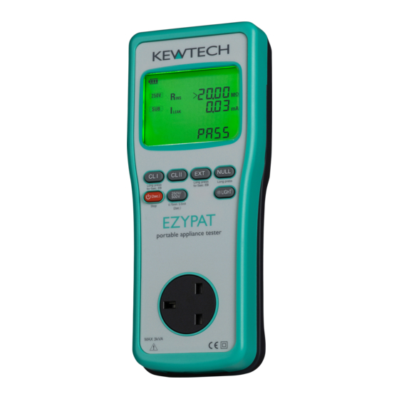
EZYPAT / EZYPAT+ / SMARTPAT (Tester) is a hand-held portable appliance tester and can test electrical safety of Class I and Class II appliances. The Tester performs test and indicates PASS/ FAIL result complying with the criteria of judgement defined in The IEE Code of Practice for In-service Inspection and Testing of Electrical Equipment: 2003.
2.4 Tester layout Connector Display(LCD) Keys Connector 2.4.1 Function Switches Switch Details Short press: Starts CLI test. (Continuity test: 1 sec.) switch Long press: Starts CLI test. (Continuity test: 5 sec.) CLII Starts CLII test. switch Short press: Starts Extension lead test. Extension (Cont.
Page 8
Switch Details Short press: Works as ESC switch. Returns to the Power stand-by screen when a test is halted by “FAIL” result. switch Long press: Turns on/ off the Tester. Short press: Switches output voltage for insulation resistance test between 250 V and 250V 500 V.
2.4.2 LCD indications <All symbols to be displayed on the LCD> Display symbols NULL value has been set. Rated voltage for insulation resistance test SUB: Substitute leakage current RUN: Leakage current test under actual working condition Rated current for RCD test Measurement in process Switches are locked and Tester is in remote test mode.
Page 10
RCD test range Prompts to check and turn on a DUT. Incorrect connection Indicates the resistance between L-L (N-N) is less than 10 Ω and polarity is correct. Open circuit warning –resistance between L-L (N-N) is 10 Ω or higher at polarity test. Crossed L-N polarity warning - resistance between L-N (N-L) is 10 Ω...
2.4.3 Connector EZYPAT EZYPAT+/SMARTPAT Test socket Insert the mains plug of DUT to this socket for the polarity test of protective conductor resistance, insulation resistance and leakage current test. Terminal for This terminal is connected to a mains supply via mains lead EZYMAIN.
2.5 Accessories (1) Mains lead EZYMAIN (EZYPAT+/SMARTPAT) This mains lead can be connected to the mains supply so that the Tester supply power to the DUT. (2) Test Lead with safety crocodile clip (MODEL7208) and Probe with Blade type Prod(MODEL7168). The probe and crocodile clip are interchangeable.
3. Specification 3.1 General specification, measuring range and accuracy Mains voltage indication: available on EZYPAT+ and SMARTPAT only Display range 30 - 270 V Hi/ Lo indication < 30 V: No voltage indication > 270 V: 270 V Resolution Accuracy ±5 V...
Page 14
Leakage current test under actual working condition: EZYPAT+ and SMARTPAT (Load current is also measured.) Item Load current Leakage current Mains voltage range 100 - 253 V/ 50 Hz Measuring range 0.10 - 13.00 A rms 0.10 - 20.00 mA rms Display range 0.00 - 13.00 A...
Page 15
Rated voltage: 230 V +10%, -15% (EZYPAT+, SMARTPAT) Rated frequency: 50 Hz Maximum load current at test 3 kVA (15sec.) socket (EZYPAT+, SMARTPAT) Outer dimension and weight Outer dimension: 261(L) × 104 (W) × 57(D)mm Weight (Tester body only): EZYPAT: Approx. 860g EZYPAT+: Approx.
within the effective range (measuring every 30 sec.) Symbols used on the Tester: Electrical circuits of equipment connected to an AC electrical CAT II outlet by a power cord. Double or reinforced insulation User must refer to the explanations in the instruction manual. Earth Crossed-out wheel bin symbol (according to WEEE Directive: 2002/96/EC) indicating that this electrical product may not be...
Note: Further information on protective conductor resistance and testing of portable appliances can be found in the Code of Practice for In-service Inspection and Testing of Electrical Equipment published by the IEE. 4. Preparation before a measurement 4.1 Visual inspection Before starting a measurement, the user should undertake visual checks on the mains lead, case and that the correct type and rated fuse is fitted to the appliance under test.
(1) Insert Test Lead with probe (MODEL7208) into the Earth terminal of the Tester, and contact the tip of the Test Lead with the earth contacts of the socket on the Tester. (2) Hold down NULL switch at least 2 sec. on any screen. (3) The screen switches to NULL screen, and NULL measurement starts.
4.3.3 Criteria setting for CL I leakage current test Either 0.75 mA or 3.5 mA can be set as threshold value for CL I leakage current test. Long press of 250V/500V switch on the stand-by screen or while measured result is being displayed at CL I/ CL II/ Extension lead test changes 0.75 mA and 3.5 mA.
5. Measuring method 5.1 Class I Test The purpose of the test carried out for Class I appliances is to check the resistance of earth continuity from exposed metal parts and the plug is below a certain level and the insulation resistance between live and neutral connected together and earth is 1MΩ...
Page 22
Connect to exposed metal parts but not rotating parts or heating elements. Power ON the DUT. RUN leak test: Connect Tester to outlet SUB leak test: No need to connect Tester to outlet. Press CLI switch for Class I test. CL I Test Detail 1.
Page 23
CL I Test Flow Stand-by Press to halt a state measurement in process. Tester performs next Voltage value is displayed test when CL I switch while the Tester is connected is pressed while a test to an outlet. is halted with “FAIL” indication.
Page 24
Rins≧1MΩ = PASS Rins<1MΩ = FAIL Mains voltage is Mains voltage is 100 V or higher. less than 100 V. SUB leakage test ILEAK≦0.75mA (3.5mA) ILEAK>0.75mA (3.5mA) = PASS = FAIL Check screen for RUN leakage test. Buzzer sounds and blue backlight blinks.
Page 25
RUN Leak/ Load current test ILEAK≦0.75mA (3.5mA) ILEAK>0.75mA (3.5mA) = PASS = FAIL Note 1: The IEE Code of Practice states that the maximum resistance should be no greater than 0.1 Ohms + the resistance of the mains cable. Therefore, if the appliance has a long mains lead then the allowable resistance can be higher than the pre-programmed 0.1 Ω.
CAUTION Where DUT ON Check function detects that DUT is off, blinking ”OFF?” appears in the LCD and the test is stopped. Turn on the DUT; then the Tester automatically resumes the test. Depending on DUTs, even they are turned on, blinking ”OFF?”...
Page 27
Connect to exposed metal parts but not rotating parts or heating elements. Switch ON the power. RUN leak test: Connect Tester to outlet SUB leak test: No need to connect Tester to outlet. Press CLII switch to perform Class II test. 1.
Page 28
CL II Test Flow Stand-by state Press to halt a measurement in process. Tester performs next Voltage value is displayed test when CL II switch while the Tester is connected is pressed while a test to an outlet. is halted with “FAIL” indication.
Page 29
Rins<2 MΩ = FAIL Rins≧2 MΩ = PASS Mains voltage is Mains voltage is 100 V or higher. less than 100 V. SUB Leakage test ILEAK≦0.25mA = PASS ILEAK>0.25mA = FAIL Check screen for RUN leakage test. Buzzer sounds and blue backlight blinks.
Page 30
RUN Leak/ Load current test ILEAK≦0.25mA = PASS ILEAK>0.25mA = FAIL CAUTION Where DUT ON Check function detects the DUT is off, blinking ”OFF?” appears in the LCD and the test is stopped. Turn on the DUT; then the Tester automatically resumes the test.
5.3 Extension Leads Test This test is for extension leads, and checks for; Protective conductor resistance between accessible conductive parts and connection of protective earth. Insulation resistance between L/N and PE. Polarity check of the Line and Neutral terminal of plug and socket. Press the EXT switch to Extension Leads test.
Page 32
Extension Lead test flow Stand-by Press to halt a state measurement in process. Tester performs next test when EXT switch is pressed while a test is halted with “FAIL” Press EXT to start a test. indication. Short press: 1 sec of continuity test Long press: 5 sec of continuity test Continuity test Rpe≦0.10Ω= PASS...
Page 33
Polarity check Polarity of L and N is Break in L or N Polarity of L and N is correct. reversed. (Cross) (Open) (Pass) Note: The IEE Code of Practice states that the maximum resistance should be no greater than 0.1 Ohms + the resistance of the mains cable. Therefore, if the appliance has a long mains lead then the allowable resistance can be higher than the pre-programmed 0.1Ω.
5.4 RCD TEST (1) PRCD test This test is to test and confirm a PRCD (Portable Residual Current Device) trips within the rated time by applying specified current. The Tester incorporates a circuit to test PRCD with Rated Tripping Current (IΔn) of 10 mA or 30 mA. PRCD trip time is measured in sequence: ×1(0°)→×1(180°)→×5(0°)→×5(180°).
Page 35
RCD Test Flow Press to halt a Stand-by measurement in state process. Long press switches IΔn: 10 mA and 30 mA RCD test stand-by screen 30mA 10mA ×1(0°) test ×1( 0°) test result Reset the tripped RCD.
Page 36
×1(180°) test ×1( 180°) test result Reset the tripped RCD. ×5(0°) test ×5( 0°) test result Reset the tripped RCD. ×5(180°) test Test results are all "PASS": If any one of test results is "FAIL": "PASS" is displayed. "FAIL" is displayed.
Page 37
● Check the connection if symbol is displayed in the LCD. Connection may be incorrect and a test doesn’t start even RCD switch is pressed. If " IΔn" setting is greater than the rated residual current of the RCD, the RCD ●...
6. Remote testing (SMART PAT) SMARTPAT incorporates Wi-Fi communication function. Tablet devices that has a special application “SimplyPats” can remotely control SMARTPAT. The special application “SimplyPats” can be downloaded from the internet site. (Internet access is required and charges may be incurred.) For further detail, please refer to Help for “SimplyPats”.
7. Backlight Press the backlight switch to turn on the backlight. Press the switch again to turn off the backlight. The backlight automatically turns off if there is no activity for about 2 min. 8. Battery / Fuse replacement DANGER Never open the Battery cover during a measurement.
8.2 Fuse Replacement (1) Disconnect the test probe from the Tester. (2) Unscrew the metal captive and open the battery compartment cover to replace the fuse. Fuse type: 10A/250V(F) Fast acting type ceramic fuse Φ 5 x 20mm. (3) Screw the battery cover back on before using the Tester.
Page 41
Kewtech Corporation Ltd. Midas House, Unit 2b Stones Courtyard High Street, Chesham Buckinghamshire HP5 1DE www.kewtechcorp.com 92-2287 06-17...
Need help?
Do you have a question about the EZYPAT and is the answer not in the manual?
Questions and answers