Table of Contents
Advertisement
Quick Links
Feb. 2005
TABLE OF CONTENTS
CAUTIONARY NOTES ...................................................2
SPECIFICATIONS.............................................................2
LOCATION OF CONTROLS ..........................................4
LOCATION OF CONTROLS PARTS LIST ...................5
EXPLODED VIEW ............................................................6
EXPLODED VIEW PARTS LIST .....................................7
WIRING FORMING .........................................................8
PARTS LIST......................................................................10
CHECKING THE VERSION NUMBER.......................15
USERS DATA SAVE AND LOAD................................15
TEST MODE.....................................................................17
BLOCK DIAGRAM.........................................................24
CIRCUIT BOARD (MAIN BOARD).............................26
CIRCUIT DIAGRAM (MAIN BOARD POWER) .......28
Copyright © 2005 ROLAND CORPORATION
All rights reserved. No part of this publication may be reproduced in any form without the written permission
of ROLAND CORPORATION.
CIRCUIT DIAGRAM (MAIN BOARD CPU) ..............32
CIRCUIT DIAGRAM (MAIN BOARD DSP)...............34
CIRCUIT DIAGRAM (MAIN BOARD USB)...............36
CIRCUIT BOARD (ANALOG BOARD) ......................37
CIRCUIT DIAGRAM (ANALOG BOARD).................38
CIRCUIT BOARD (SW SHEET) ....................................40
CIRCUIT DIAGRAM (SW SHEET,SW BOARD) ........42
CIRCUIT BOARD (CD CN BOARD) ...........................46
CIRCUIT DIAGRAM (CD CN BOAR).........................46
ERROR MESSAGES ........................................................47
17058313E0
SERVICE NOTES
Issued by RJA
Printed in Japan (0500) (NB)
BR-1200CD
Advertisement
Table of Contents

Related Manuals for Roland BR-1200CD


Summary of Contents for Roland BR-1200CD
-
Page 1: Table Of Contents
USERS DATA SAVE AND LOAD........15 CIRCUIT DIAGRAM (SW SHEET,SW BOARD) ..42 TEST MODE..............17 CIRCUIT DIAGRAM (SW SHEET,GUITAR INPUT BOARD) ..44 INITIALIZING ALL BR-1200CD SETTINGS (INITIALIZE) ..20 CIRCUIT DIAGRAM (SW SHEET,+5V POWER BOARD) ...45 SYSTEM SOFTWARE UPDATING INSTRUCTIONS ..23 CIRCUIT BOARD (CD CN BOARD) ......46 BLOCK DIAGRAM............24... -
Page 2: Cautionary Notes
Feb. 2005 BR-1200CD CAUTIONARY NOTES SPECIFICATIONS BR-1200CD: Digital Recording Studio User data status Tracks User data status after each of the following processes is described below. Track: 12 V-Track: 192 (16 V-Tracks per each Track) Whenever carrying out procedures that involve deleting or erasing user data,... -
Page 3: Power Supply
MIC 1, 2 jacks (TRS balanced/XLR) PHONES jack (Stereo 1/4 inch phone type) GUITAR/BASS jack (1/4 inch phone type) Power Supply DC 12 V; Supply AC Adaptor (Roland PSB-3U) Power Consumption 3.0 A Dimensions 478 (W) x 297 (D) x 95 (H) mm... -
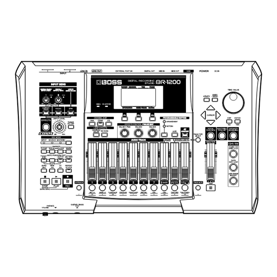
Page 4: Location Of Controls
Feb. 2005 BR-1200CD LOCATION OF CONTROLS fig.panel... -
Page 5: Location Of Controls Parts List
Feb. 2005 BR-1200CD LOCATION OF CONTROLS PARTS LIST [PART] PART CODE CATEGORY PART NAME DESCRIPTION Q’TY 00900145 KNOB,BUTTON D S-KEYTOP SD1H BLK 01904112 DIODE LED(RED) SLR-342VCT32 N.P.Q RANK 01340290 SWITCH TACT SWITCH EVQ11A H=5.0 00900156 KNOB,BUTTON D S-KEYTOP SD2H BLK... -
Page 6: Exploded View
Feb. 2005 BR-1200CD EXPLODED VIEW fig.explo-A Fig.1 Fig.2 Please refer to Fig.2 Please refer to Fig.3 Fig.3 Fig.4 27 28 Please refer to Fig.4 Please refer to Fig.5... -
Page 7: Exploded View Parts List
Feb. 2005 BR-1200CD fig.explo-C Fig.5 Fig.6 Please refer to Fig.6 EXPLODED VIEW PARTS LIST [PARTS] [SCREW] Part Code Part Name Description Part Code Part Name Description 02013090 F C-KEYTOP MX1H CLR 40012534 SCREW 3X6 BINDING TAPTITE S FE BZC 01783945... -
Page 8: Wiring Forming
Feb. 2005 BR-1200CD WIRING FORMING VR/LED BAN CARD (BNCD-P=1.25-K-34-130 #03789856) ···Don’t hit the CD holder and fold up from connect side. CD IDE (WIRING HDD IDE #02904623) ···Fold up into board internal fig.BR1200-TOP side. fig.C fig.BR1200-ANALOG fig.A fig.BR1200-HDD SW BAN CARD (BNCD-P=1.25-K-20-110 #03789901) ···Top of knob, don’t lay it down to ANALOG BOARD side. - Page 9 Feb. 2005 BR-1200CD fig.E fig.BR1200-NOISE 10. Noise measure ··· The analog GND synchronizer is short-circuited in the AWG24 line. Depends on the analog board revision since serial No. ZT34785, and the measures do not exist. fig.F fig.BR1200-CU 11. EMI measure ···...
-
Page 10: Parts List
Feb. 2005 BR-1200CD PARTS LIST fig.part1e Due to one or more of the following reasons, SAFETY PRECAUTIONS: parts with parts code ******** cannot be supplied as service parts. The parts marked have safety-related characteristics. Use only listed parts for replacement. - Page 11 12169406 LED SPACER LDS-100Y 10MM on SW ******** 5V POWER BOARD ASSY NOTE: ‘BR-1200CD 5V POWER BOARD ASSY’ includes the following parts. 03785389 5V POWER WIRING on 5V ******** GUITAR BOARD ASSY NOTE: ‘BR-1200CD GUITAR BOARD ASSY’ includes the following parts.
- Page 12 Feb. 2005 BR-1200CD DIODE 15019126 1SS133 T-77 SWITCHING DIODE D1,D2,D3,D4,D5,D6,D7,D8,D9,D10,D11,D12,D13 ,D14,D15,D16,D17,D18,D19,D20,D21,D22,D23,D2 4,D25,D26,D27,D28,D29,D30,D31,D32,D33,D34,D 35,D36,D37,D38,D39,D40,D41,D42,D43,D44,D45, D46,D47,D48,D49,D50,D51,D52,D53,D54,D55,D5 6,D57,D63,D64on SW,D62 on GUITAR 00785856 SLR-342VR3F LED1,LED2,LED19,LED20,LED1,LED2,LED19,L ED20,LED21,LED29,LED30,LED31,LED32on SW 01904112 SLR-342VCT32 N.P.Q RANK LED(RED) LED13,LED15,LED16,LED17,LED18,LED22,LED 23,LED24,LED25,LED26,LED33,LED34,LED35,L ED36,LED37,LED38,LED39on SW 15029347 SLR-342VC3F LED (RED) LED28 on SW 15029348...
- Page 13 Feb. 2005 BR-1200CD RESISTOR 02678545 RR0816P-153-D MTL.FILM RESISTOR Chip on ANALOG POTENTIOMETER 03783023 EVUJFUFK315D 100KRD 9M/M ROTARY POTENTIOMETER VR1,VR2 on SW 03789645 EVUF2KFK3B54 POTENTIOMETER VR3,VR4,VR5 on SW 02896712 EVUF2KFK4B54 50KB 9M/M ROTARY POTENTIOMETER VR6 on SW 01677312 EWAP1AC10 B54 (50KB/MS)
- Page 14 Feb. 2005 BR-1200CD CONNECTOR 02014445 20FE-BT-VK-N CONNECTOR CN7 on MAIN 02896934 52559-3092 CONNECTOR CN9 on MAIN 01908634 14FE-BT-VK-N CONNECTOR CN12 on MAIN, CN14 on ANALOG 02018990 34FE-BT-VK-N CONNECTOR CN4 on MAIN 13369570 B2B-PH-K-S (2P) CONNECTOR CN8 on MAIN 13369594 B4B-XH-A...
-
Page 15: Checking The Version Number
CD-R/RW Discs (User Backup) • User bass pattern The data described above will all be saved. The BR-1200CD allows you to back up the following types of user data to CD- Loop Phrase: R/RW discs. User loop phrases will all be saved. - Page 16 (HDD Backup) The BR-1200CD allows you to back up all of the data on the internal hard disk onto CD-R/RW discs, regardless of the type of data or the song in which it is used. Data that’s been backed up this way can later be recovered whenever needed.
-
Page 17: Test Mode
• Mixer or other device capable of balanced output (for input of signals to • The range of available write speeds can sometimes be limited by the type XLR jacks) of media being used. In such a case, the BR-1200CD will allow you to • Oscilloscope select only the supported speeds. - Page 18 Feb. 2005 BR-1200CD 11. MIC1 PHANTOM PLAY -> PLAY goes off -> REC goes off 12. GUITAR/MIC1 AUDIO V-TRACK 13. MIC2 A/B TRACK1 -> TRACK1 goes off 14. MIC2 PHANTOM TRACK2 -> TRACK2 goes off TRACK3 -> TRACK3 goes off 15.
- Page 19 Feb. 2005 BR-1200CD 5.ENCODER & LCD 11.MIC1 PHANTOM Rotate the ENCODER to the right (clockwise) and confirm that the LCD Press the [ENTER] button to switch PHANTOM on and off. becomes darker. With PHANTOM on, use a tester to measure the voltage between the...
-
Page 20: Initializing All Br-1200Cd Settings (Initialize)
Connect an oscilloscope to LINE OUT L/R. Input a 200 Hz rectangular wave at 1 mVp-p to LINE IN L/R. The Initialize function allows you to return all of the following BR-1200CD Confirm that the waveform from LINE OUT L/R alternately appears and parameters to their original settings. - Page 21 Press [ENTER/YES] once again. MIXER icon The BR-1200CD will start the initialization process. When this process fig.08-270 has finished, the message “Complete!” will appear and you’ll automatically be returned to the top screen.
- Page 22 A new song “SONG 001” will be created on the hard disk. The state of progress of the initialization will be shown on the display, and you should not turn off the BR-1200CD until this procedure has been completed. Failure to observe this precaution could considerably reduce the life span of...
-
Page 23: System Software Updating Instructions
Feb. 2005 BR-1200CD SYSTEM SOFTWARE UPDATING INSTRUCTIONS Updating from CD-R Required Items • Updater CD-ROM (#17041569) Simultaneously hold Procedures down the [STOP] and [PLAY] buttons and press the [POWER] button. Continue to hold down the [STOP] and [PLAY] switches until the updater screen is displayed. -
Page 24: Block Diagram
Feb. 2005 BR-1200CD BLOCK DIAGRAM fig.BR1200CD-BLOCK... -
Page 25: Circuit Board (Main Board)
Feb. 2005 BR-1200CD CIRCUIT BOARD (MAIN BOARD) fig.MAIN-P-SC1 View from components side... - Page 26 Feb. 2005 BR-1200CD fig.MAIN-P-SC2 View from foil side...
-
Page 27: Circuit Diagram (Main Board Power)
Feb. 2005 BR-1200CD CIRCUIT DIAGRAM (MAIN BOARD POWER) fig.MAIN-POWER-SC hard disk power CPU power supply(3.3V) HD power TP364 TPC8303 3.3V_CPU IC25 UPC29M33T TP365 N.I.U N.I.U R108 TP366 N.I.U C205 C295 C206 100/16 C208 C207 C273 470/16 R117 R109 C209 N.I.U N.I.U... -
Page 28: Circuit Diagram (Main Board Analog)
Feb. 2005 BR-1200CD CIRCUIT DIAGRAM (MAIN BOARD ANALOG) fig.MAIN-ANALOG-SC 40mA/0.35 W C299 A 3. 3 IC29 UPC29L33T C233 C234 10/16 C240 C241 R138 10/16 10k(MF) C239 R137 C243 10p C238 CN12 R139 10/16 14FE-BT-VK-N 100k R141 CN13 30k(MF) 10FE-BT-VK-N C246... -
Page 29: Circuit Diagram (Main Board Cpu)
Feb. 2005 BR-1200CD CIRCUIT DIAGRAM (MAIN BOARD CPU) fig.MAIN-CPU&GA-SC A[0:19],A[21:23] A[0:19],A[21,23] D[0:15] D[0:15] D 3. 3 IDE_RESET# RESET# 32M FLASH D 3. 3 IC1B TO HDD #CS2 N1608Z601 SN74LV04APWR HD power 12 V #CS4 POWER EXBE10C103J C307 #CS5 TP24 N.I.U... -
Page 30: Circuit Diagram (Main Board Dsp)
Feb. 2005 BR-1200CD CIRCUIT DIAGRAM (MAIN BOARD DSP) fig.MAIN-DSP-sc A[0:13] A[0:19],A[21,23] D[0:7] D[0:15] ESP#1_TRS[0:5] ESP#1_TRS[0:5] ESP#2_TRS[0:5] D 3. 3 D 3. 3 GA_TRS[2:5] GA_TRS[2:5] C153 C154 C155 C157 C158 TRR ch select C160 C161 C275 C162 ESP#1 TRR/0ch->23ch GA TRS,... -
Page 31: Circuit Diagram (Main Board Digital Out)
Feb. 2005 BR-1200CD CIRCUIT DIAGRAM (MAIN BOARD DIGITAL OUT) fig.MAIN-DOUT-SC DAC/DIT D 3. 3 D 3. 3 C146 C149 10/16 10/16 DIGITAL OUT C147 IC17 C148 D 3. 3 CS8406 C145 CDOUT D_CCLK SDA/CDOUT SCL/CCLK D_CDIN D_CS# AD0/CS AD1/CDIN CN10... -
Page 32: Circuit Board (Analog Board)
Feb. 2005 BR-1200CD CIRCUIT BOARD (ANALOG BOARD) fig.analog-sc1 View from components side fig.analog-sc2 View from foil side... -
Page 33: Circuit Diagram (Analog Board)
Feb. 2005 BR-1200CD CIRCUIT DIAGRAM (ANALOG BOARD) fig.ANALOG-SC R129 R130 R131 R140 100k 100k 100k 100k to SW BOARD R123 DTC114EUA DTC114EUA DTC114EUA DTC114EUA 12FE-BT-VK-N IC6A 10/16 2SK880GR 2.7k R124 M5218AFP R142 10/16 52147-510 0(22/16) 2SK880GR R132 C100 analog power... -
Page 34: Circuit Board (Sw Sheet)
Feb. 2005 BR-1200CD CIRCUIT BOARD (SW SHEET) fig.SW-SC0... -
Page 35: Circuit Diagram (Sw Sheet,Sw Board)
Feb. 2005 BR-1200CD CIRCUIT DIAGRAM (SW SHEET,SW BOARD) fig.SW-SW-SC to MAIN BOARD EN1B EVE_GC1_F20_24B D 3. 3 EN1A EVE_GC1_F20_24B to ANALOG INPUT 1 INPUT 2 BOARD CN3 VR(1M,D) VR(1M,D) 34FE-ST-VK-N +3. 3 EVUF2KFK3B54(50kB) EVUF2KFK3B54(50kB) EVUF2KFK3B54(50kB) EVUF2KFK4B54(50kB) 12FE-ST-VK-N VR1B VR2B EVUJDUFK315D EVUJDUFK315D +3. -
Page 36: Circuit Diagram (Sw Sheet,Guitar Input Board)
Feb. 2005 BR-1200CD CIRCUIT DIAGRAM (SW SHEET,GUITAR INPUT BOARD) fig.SW-INPUT-SC NIU(1SS133) NIU(1SS133) INPUT1(Hi-Z) YKB21-5006 10/16 R104 1SS133 0(BL02RN2) 1/50 RIBON 5P IC2A GUITAR_IN to ANALOG R105 M5238AP 100p BOARD CN2 GUITAR_JK_SW IC2C M5238AP IC2B M5238AP to ANALOG BOARD CN6 PHONES... -
Page 37: Circuit Diagram (Sw Sheet,+5V Power Board)
Feb. 2005 BR-1200CD CIRCUIT DIAGRAM (SW SHEET,+5V POWER BOARD) fig.SW-5V-SC N.I.U(1SS387) 3.4A ma x 3.2A max 3.5A ma x TSL1315S-470K3R4(47uH) ELC18B101 POWER 1000/16 RB081L-20 3k(metal) 4.0A max WIRING_5V_POWER 2200/16 N.I.U PQ1CG3032FZ to MAIN BOARD CN11 1k(metal) N.I.U... -
Page 38: Circuit Board (Cd Cn Board)
Feb. 2005 BR-1200CD CIRCUIT BOARD (CD CN BOARD) fig.CD-SC1 fig.CD-SC2 View from foil side View from components side CIRCUIT DIAGRAM (CD CN BOAR) fig.CD-CN-SC KX14-50KL7.9H1 AUDIO-L AUDIO-R AUDIO-G 75401 -0X0-B-S RESET# RESET# DD10 DD10 DD10 DD10 DD11 DD11 DD11 DD11... -
Page 39: Error Messages
Action 2: Reduce the number of songs to be written, then try again. Event Memory Full! CD Read Error! Cause: The BR-1200CD has used up all the events that can be handled by Cause: An error occurred while reading data from the CD-R/RW disc. one song. - Page 40 Marker Memory Full! Cause: You attempted to execute a track editing operation without Cause: The BR-1200CD has used up all the marker memory (100 markers) specifying the track to which the operation will apply. that can be handled by one song. Action: Specify the track, and then execute the editing operation.
Need help?
Do you have a question about the BR-1200CD and is the answer not in the manual?
Questions and answers