
Subscribe to Our Youtube Channel
Related Manuals for GSE 350 IS


Summary of Contents for GSE 350 IS
- Page 1 GSE Model 350/355 N TRI N S I C A FE Technical Reference Manual Version 1.0...
- Page 2 Model 350/355 IS Technical Reference Manual Version , - -...
- Page 3 GSE. GSE Locations GSE Scale Systems 42860 Nine Mile Road Novi, 48375 U.S.A. Phone: 755-7875 GSE Canada, Inc.
-
Page 4: Table Of Contents
Table of Contents ........................... CHAPTER 1:INTRODUCTION ............................ R E A A ZAR DO U S ..............................Hazard Grouping ..............................of Hazard Duration ..............................Temperature Codes ................................Definitions ............................Entity Evaluation Concept ............................Entity Rating ............................................................................................... U N C TI O N S .............................. - Page 5 ......................Exiting Setup Mode and Saving Changes ................................ PARTS COUNTING .......................................................... Activation Methods (General) ......................................................... Feature (General) ............................Pause Fearure {General) ....................Changing Targets from the Weigh Mode (General) ......................Target Weight (General) Change Example ............................... Bargraph (General) ER C ENTA G E ....................
- Page 6 ....................................................O TE PER A TI ............................ER IA L O PER A TION ............................Display Capture Ufdity ..........................N DI C A T O R M WA RE ............................... Prepare for upgrade ..............................Load Flash File ........................... CHAPTER CALIBRATION.
-
Page 8: Chapter 1:Introduction H A Zar Do U S A
CHAPTER I~INTRODUCTION Thank you for selecting the GSE Model 3501355 Intrinsically Safe Indicator. The Model 350 and Model 355 maintained Model 350 or continue the GSE tradition of Excellence Weighing. A properly installed Model 355 IS will provide years of reliable, accurate performance. -
Page 9: Duration Of Hazard
Division 1 Division E M PE R A T U R E O DE S Class I, Division I , Groups A, B, C Class I, Division 1 locations are those in which hazardous of flammable gases vapors exist concentrations continuously, intermittently or periodically under normal operating conditions. - Page 10 Class I, Division 2, Groups A, & D Class I, Division 2 locations are those in which hazardous concentrations flammables exist only under unlikely conditions of operation. equipment and associated wiring which are incapable of reIeasing As such, flammable sufficient electrical and thermal energy ignite gases or vapors under “normal”...
-
Page 11: Definitions
This means that not only can the instrument be used with GSE also FM Approved Ioadcells and peripherals, but they be used with manufacturer’s FM Approved... -
Page 12: Entity Rating Definihons
met, then and remain intrinsically criteria are the combination may safe. If the specific be connected capacitance and inductance ratings of the wiring are unknown, use a capacitance of 6OpF/ft inductance When connecting a Model to another intrinsically safe device, the entity ratings must be compared and satisfy the conditions shown in the following table. -
Page 13: Entiry Rarings Approvaw
The Model 3501s and 3551s indicators and options been approved for the following have hazardous areas: Excitation) Intrinsically Safe for Class I-BI, Division 1 Group A-G Intrinsically Safe for Class I, Zone 0, Group LIC-IIA Nonincendive for Class Division 2, Group A-D Nonincendive for Class Zone 2, Group IIC-IIA Suitable for use in Class... -
Page 14: Standard Functions
The Model 350 and 355 IS indude built-in functions that the Indicator Setup. Refer enable through the setup and Chapter 3 : Configuration for information operation the foIlowing standard functions: Check-weighing Parts counting Remote key operation Selectable, built-in data transmission formats Custom Features Three display... -
Page 15: Display
COMMUNICATION RS-232 (2) RS232 communication ports, with hardware handshaking KEYPAD 350 IS numeric, durable elastomeric (rubber) SAFE AREA OPTIONS Battery Charger hours Charges completely discharged battery option Universal AC input 85-265VAC 50160 HAZARDOUS AREA OPTIONS indicator swivel bracket. 200... -
Page 16: Lcd Display
The displayed value ounces, pound ounces o r grams. IS KEYPAD The Model 350 IS offers a sealed 5-button elastomer keypad is used for operator input. Each key is assigned combinations are also used. Each key has secondary functions; allowing two distinct functions. - Page 17 C O N D A RY U N C TI O N S The Model keypad performs different functions in the Weigh Mode, Setup Mode, Calibration Mode. Secondary functions for each key allow you additional perform tasks. . - . . Count Mode Setup M d e clears an...
-
Page 18: Keyp
Keypad The Model keypad performs different functions in Mode, the Setup Mode, and the Weigh Calibration Mode. The number keys make value or piece weight easier. entering a tare average Count Mode Setup Mode O DE Exits the Setup Mode Performs gross zero function... -
Page 19: Weigh Mode Functions
If the keypad was enabled, the display will show IS, hold down key of the 350 IS keypad keypad while power is applied by pressing the key. Weigh Mode Functions have five primary Weigh Mode functions:... -
Page 20: 2: Installation
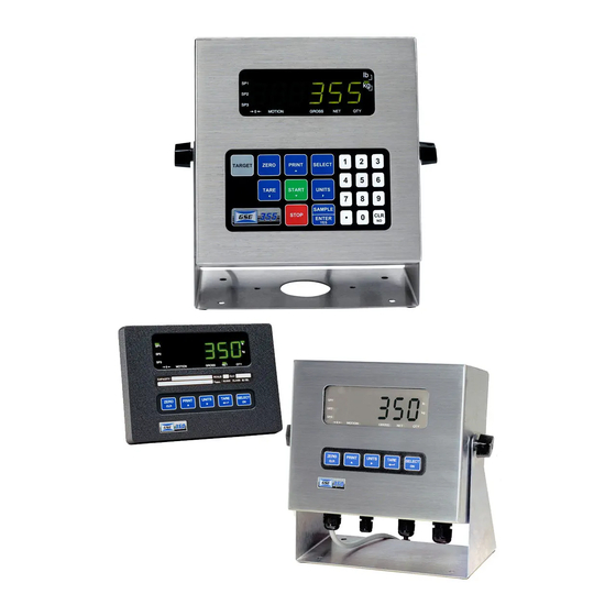
See the system diagrams included of other the entity concept. with 350 IS or IS indicator. T h e outline drawings provide measurements needed for indicator installation. Figure 5: Model 350 with Standard Bracket... -
Page 21: L O Ad Cell C O N N Ec Ti O N S
Figure 7: Model IS with Battery Swivel Bracket Figure 8: Model with Battery Bracket Cell Connections Load shield cable with 16 to 24 AWG stranded wire is for load recommended . . - . -..connections. Rout the load cell cable through the strain on the bottom of the summing... -
Page 22: Aremote Key Connfltions
Refer to the diagram below for connections to each communication port. Remote Key Connections The Model 350 IS and Mode1 355 IS accommodate remote keys connections. A remote switch may h e main board remote... -
Page 23: Hazardous Area Options
Do not apply external voItage remote key contact closure is required terminals! Only a activate the remote key input. A closed The open circuit voltage across the remote key pins switch will conduct about 0.25 contacts recommended. A Mercury-wetted switch will also work well. -
Page 24: Volt And 8 Volt Excitation
Outline Figure Supply Drawing Power O W ER XTE N S I O N CABLE The extension cable either 25' length. This is for mounting the AC converter away from the indicator. I O N VOLT AND VOLT X C ITAT available for Model 350 IS and Model 355 IS. -
Page 25: Chapter 3: Configuration
CHAPTER CONFIGURATION Entering the Setup Mode (Model sequence of keystrokes is used prevent accidental changes the Indicator Setup, gain access Setup Mode: within five seconds, or the indicator will These keystrokes must the Weigh Mode. made return access the Setup Mode: From the Weigh Mode, press Setup... -
Page 26: Selecting A Parameter
When exiting the Setup Mode, the Model 3501355 prompts whether to enter the Calibration Mode Mode. (See Chapter procedures). The display will then prompt save any changes. Entering the Setup Mode (Model 355 IS) keystrokes is used to gain access prevent accidental changes the Indicator Setup, a sequence Setup Made:... - Page 27 DISPLAY READS 2. Press DISPLAY READS P111.09 3. Repeat back up one parameter. 355 IS): access Press DISPLAY READS 2. Press DISPLAY READS 0.01 Repeat back up one parameter. When accessing parameter, the parameter number appears briefly. display then toggles between parameter name and selection.
-
Page 28: C H An G In G A P A Rameterv
ELE C TI O N ARAMETER S Selection parameters have a predefined list of choices to pick from. Each choice is numbered and corresponds to a certain value. The number is shown the right of the decimal point within the choice parameter number. -
Page 29: Saving Parameters
I S ) : setup scale value Access the setup mode. DISPLAY READS Key in accept the entry. DISPLAY READS Saving Parameters Setup Mode and save changes (350 IS): exit Press begin exiting Setup Mode. DISPLAY READS Calibration Mode. Press bypass DISPLAY READS... - Page 30 Press setup changes. save DISPLAY READS Enter Press complete exit. DISPLAY READS To exit the Setup Mode changes IS): save Press begin exiting Setup Mode. DISPLAY READS 2. Press bypass Calibration Mode. DISPLAY READS Enter 3. Press setup changes. to save DISPLAY READS Enter complete exit.
-
Page 31: Factory Default
Mode without (355 IS): exit Setup saving changes begin exiting Setup Mode. DISPLAY READS Enter Press bypass Calibration Mode. DISPLAY READS Enter exit without Press saving changes. DISPLAY READS Enter undo changes. Press DISPLAY READS complete exit. DISPLAY READS Factory Default Parameter 65001 and Model 65002... -
Page 32: List O F Parameters
List Parameters Model IS and Mode1 have several parameters that can configured your specific application. Below is table of the available parameters. Also refer page 27 for explanations of each parameter. Table Parameter Number... - Page 33 Parameter Motion Comm 1 Print Transmission Comm 2 Baud Rate Comm Data Bits Comm 2 Parity Stop Bits Comm Comm 2 Handshake Comm Transmit Comm Motion Transmission Print OIML Enforce DispIay Function Selections) NTEP Disable Enforce Enable Disable Disable Enable / Disable (Toggle) 1.2 hours 12 hour124...
-
Page 34: Parameter Map Details
ARA M ETE R Full Scale Value (Key in) Denotes the full scale capacity. This value should not exceed the rated capacity of the weighing device. Division Size (Selection) Indicates the count-by decimal point. Pressing (Model (Model IS) will automatically select the choice closest to 10,ooO divisions without exceeding... - Page 35 Specifies how divisions can in terms of a percentage of full scale many zeroed 10). of weight values zeroed through the zero tracking cannot this range. and auto exceed A zero range of commonly used with large tank scales to avoid zeroing of a full or accidental...
- Page 36 data bits for the transmission. Select 7 or 8 Parity (Comm 1) (Selection) Select Odd, Even or for the transmission parity. None P203 Bits (Comm 1) (Toggle) Stop I or 2 stop bits for communication Select port transmissions. (Comm 1) P204 Comm Handshake (Selection)
- Page 37 Selection Choice Number transmissions P230.00 P230.01 Press [PRINT] key. Sends transmission with P 2 3 0 . 0 2 continuously. Sends transmissions Send single transmission after weight is reached and P230.03 Cycle below display value F.S. transmission. reset P232 Send Stability (Comm 2) (Toggle) Enabling Send Stability will delay any transmissions until a no-mo tion condition exists.
- Page 38 (toggle) Style DATE Determines format style, U.S.A. or Int’l. If set for U.S.A, the date will resemble 01/26/01. If set international, the date will resemble key from the weigh mode. The weight will Allows the time and date to viewed with the continue to be updated when viewing the time or date.
-
Page 39: Preset Transmit Selections
Setpoint operation. Choose between None, ChecP, Fill, Batch, Discharge, Both, Sets ChecA or Independent. General Setpoint Selup page and operation. Preset Transmit Selections The Model 350 IS Model IS provide 14 preset formats for printing tickets o r sending data computer. Only one format custom may be enabled at a time. - Page 40 Choice 4: Choice 5 : Choice 6: Choice Choice Choice 10: Choice Choice send to text mode and Use choice remote display that is terminator. Choice 14 (Simulates NCI 3835): Status of all Transmitting the setpoint will reflect the current the setpoints, regardless which setpoint status...
-
Page 41: Elements Of A Custom Transmit
Custom Transmit output M o d e l configured for a application such as remote serial custom display format, computer program format, or a ticket format. The custom transmit must be designed in computer-transmittable ASCII text file. The custom only be loaded into transmit the custom transmit format... -
Page 42: Entering Ascii Text
Mode end of the existing transmit This accesses Setup then clears transmit so that a new entered. may be Tare and Net Parameters Gross, Exit Setup Mode Changes Save Figure ASCII T E NT E RIN G ASCII is defined as printable characters, including alpha-numerics as well as punctuation and symbols. - Page 43 Table 2 : ASCII HEXADECIMAL CONVERSION CHART CHAR t i 7 3 6 3 Most printers require return line feed a carriage avoid leaving print preceding data in printer data buffer. 35 for list of ASCII codes. page...
-
Page 44: Parameter Selecrion Numbers
A RAME T ER U MB E R S following sequence enters parameters parameter number, %e%e into a custom transmit: code, and then with no intervening spaces. format %e 0 %e%e Initiates Format Enters Format Parameter Enters Parameter Choice and Ends Parameter Number Initiates... -
Page 45: Parts Counting
format required, add the choice numbers a combination of choices is together and enter their name (Ib) and format example, print net weight without the (Net) or units to print it code. minimum width: NOTE: Only one of the choices 0-3 may be used one time. - Page 46 5 , IO, 20, 50 and 100. Press toggle sample between amounts DISPLAY READS Add the pieces sampled and press sample display the current quantity. DISPLAY READS To sample using se!ectable counts IS): fixed (355 to perform an auto-tare. The scale prompts pieces.
-
Page 47: Activation Methods (General)
Setpoint Setup The Model several pre-programmed scale setpoint applications available at P5 100. Various related setpoint parameters may appear which of the standard programs is chosen. Table 5 according to describes the available setpoint operations. Table 5: Setpoint Operations Absolute check-weighing. tolerances based on discrete values. -
Page 48: Pre-Acls (General)
Activation Method Description waits for a no-motion condition, activates then tares scale zero. the setpoint. Tare Operation setpoint is then activated. The appropriate KEY] [REMOTE closure activates the selpoint. The remote key function (assigned at Remote Keys over-ridden. tart the setpoint after motion ceases. Auto-S Automatically activates... -
Page 49: Changing Targets From The Weigh Mode (General)
Pause Setpoints Model 350 IS When invoked, Pause deactivates all setpoiots. The display will show: will resume The Pause feature has four settings: current cycle; other keypress will abort Pause Action feature disabled. Pause Current cycle paused Keypad setpoints deactivated. -
Page 50: Change Target Weight
ER A L H AN G E AR G ET G H T XAM P L E The target for the fill setpoint operation is Targ This is a setpoint-related parameter and automatically becomes an available mode when Fill is configured in the setpoint setup. - Page 51 “BARS (BARGRAPH ARROWS) If the the low first the specified percentage (set at turns number of divided by 8 determine the grads, graph is off. entire Lower Limit is set at for 80% (Bar weight = 40 = (1018 = 1 .
- Page 52 40.00 to 45.00 to50.00 45.00 Figure 14: Example #2 Bargraph Segments (Weight Value) "Below, Within and Above Figure 15: ExampIes o€ tbe Bargraph NOTE: (bargraph for filling and emptying modes) the bars For modes other than check-weighing, will be on only while the setpoints are on and during the "Done"...
-
Page 53: Setpoint Activation {Percentage Check- Weighing)
Instead target. IS). keying in the target value from T a r g 1, press (350 IS) (355 Press (350 (355 IS) again accept the target. PctLo the subsets for Targ entered as percentage values. -
Page 54: Er C Enta G E
Press DISPLAY READS the current fill Press to view target. DISPLAY READS Press 400 set a new fill target of 400 DISPLAY READS WTargl- Press to select Pre-Act 1 (subset) value of 28 lbs. READS DISPLAY Press select the he-Act 2 (subset) value of 1.5 Ibs. DISPLAY READS FPA 2 Press select... -
Page 55: Activation Merhod (Fill)
fill operation The fill program is used for single-speed dual-speed filling operations. dual-speed for both fast and a fill mode. During a fast-fill, setpoints and 2 are activated. During a slow- allows slow fill or single-speed fill, only setpoint 1 is activated. Description Setpoint Selection... -
Page 56: Pause Feature (Fill)
EA RN EAT U RE learn feature available which allows the indicator Pre-act 2 has adjust the final cutoff based on changing environmental conditions. See Leam Feature (General) on page 41 for ‘learn’ feature details. A U S EAT U RE pause feature (keypress, remote key closure or both) is available for the filI operation. -
Page 57: Activation Method (Batch)
..Setpoint Description Selection Function PrAc 3 Pre-act value (final cutoff f o r ingredient 19.1 3 activation start 3 Setpoint Key-In Parameters on page 2 1 for instructions on using front panel keys for entering data. C T IV ATI O N METHOD A T C H The filling of each ingredient begins when... -
Page 58: Discharge
Pre-acts 1 and always available as subsets of their respective targets from the Weigh Mode. 2 are XAMP L E AT C H a system make a 50,000 lb With system batch with lbs.) water and caramel color lbs.), ingredient should with and subsequent ingredients should... -
Page 59: Activation Method (Discharge)
Table 9: Function Description Selection Select discharge Discharge setpoint operation. Final value. Targ dispensed target net or count (auantitv) Select PA 1 Pre-act 1 value (fast-to-slow value; single-sped). s t a r t Setpoint activation method. P5 107.0 Pre-act (final P A 2 value pre-act... -
Page 60: Target Changesfrom (He Weigh Mode (Discharge)
I SC HA R G E A U S E EAT U The standard pause feature (keypress, remote key closure or both) is available for the discharge operation. See Pause Feature (General) page 41 for pause function details. A R G E T CHANGES FROM THE WEIGH O DE (DISCHARGE) T a r g mode... -
Page 61: Activation Method (Both)
vessel and Setpoint is used for product discharge. The ‘both’ program uses values for two targets and two pre-acts. Both be based alike o r quantity. quantity is selected). must count targets (net Selection Function Description both setpoint operation. Select 10 1 Vessel fill value. -
Page 62: Pause Feature (Borh)
AT U RE O TH The standard pause feature (keypress, key closure or both) i s available for Both operation. See remote Pause Feature (General) on page 41 for 'pause' functions details. TARGET CHANGES FROM THE W H G H O DE (BOTH) Targ 2 automatically become available modes When... - Page 63 (355 T a r g 1, press (350 Press IS) again to accept the target. To change targets from Weigh Mode (350 IS): Press DISPLAY READS press to view the current fill target. DISPLAY READS press to set a target...
-
Page 64: Example (Absolure Check-Weighing)
5 . Press select the Pre-Act (subset) value of 1.5 Ibs. DISPLAY READS ,PA 2 6. Press select Pre-Act 2 value lbs. a new DISPLAY READS to display the Press current Gross Weight. DISPLAY READS ,1512 from the Weigh IS): change targets (355... -
Page 65: Setpoint Activation {Independent)
Base Select from Net, Gross for Setpoint 2. 2 when wcieht is above below. P5 132.0 Act 2 Activate setwint Setpoint 2 target for weight rise T a r g either above fall below. 2 stability setting. 134.0 Setpoint 135.0 Rset 2 selection for setpoint 2. -
Page 66: Example (Independent)
the reset for setpoint is to 'value', then pressing alone will allow access to the subset target. Rtrg 1,2 3 are respective subsets for Targ 1,2 and 3. Chunging Targets from the Weigh Mode on page 42 Weigh Mode. (General) XAMP N DE P E ND E N T that fills a weigh hopper from... -
Page 67: Setpoint Activation
page 21 for instructions on using the front panel keys for entering data. TI O N AR G ET VIATI O N H E C K EI G HIN G ) TIVA order for the annunciators to activate, displayed value must be at least graduations above zero. -
Page 68: Example (Target Deviation Check- Weighing)
display the 7. Press current Gross Weight. DISPLAY READS IS): change targets from Weigh Mode 1 . Press to view current fill target. DISPLAY READS b T a r g l - Key in value Example the new press target DISPLAY READS b T a r g l - XAMP L E AR G E T... - Page 69 43.75 45.00 45.00 46.25 46.25 47.50 47.50 48.75 48.75 to 50.00 Figure 16: Example Figure Lower Limit set at (Bar weight 5 Ibs) (4018 NOTE: Right-side bars will have the same bar) the left-side bars. They represented mirror image of each other.
-
Page 70: Time And D Ate Seitl.jp (Model 350 1S)
Figure 18: Examplw of the Bargraph "Below, Within and Above Tolerance" filling NOTE: (bargraph and emptying modes) For modes other than check-weighing, the bars wiU be are on on only while the setpoints and during "Done" the end fill. The bar weights will be calculated similar to the check-weigh modes of operation stated for filling, above that the percentage will be based on the actual target, rather than the low-limit value... - Page 71 if P502 is enabled. time and from the weigh mode with the date can be accessed Enter the date is acceptable, press To enter 70 prompt EXAMPLE: 0 1 . 0 9 . 0 4 (January toggle through the numbers month.
-
Page 72: Time And Remo Te Key Oper A Ti O N
numbers Press to toggle through the minutes, to enter DISPLAY READS 16.3 Press once move the cursor. Press select digit. next DISPLAY READS 16.32 Press twice to the decimal point separate minutes f r o m the seconds. move over DISPLAY READS 16.32. -
Page 73: R E Mote Ser Ia L O Per A Tion
Press to except the time Press weigh mode, return Remote Key Operation Model 350 and Model 355 IS has key operations choose from: Print, four selectable Tare, remote Zero the remote input. Table describes the available remote key operations. See Remute Key Connection pages 15 for information on connecting remote key input device. -
Page 74: Display Capture Ufdity
355 IS have flash memory on the main The Model 350 IS and Model board where the parameters are stored. possible to update the f i r m w a r e simply by a computer. The firmware is loaded into... -
Page 75: Prepare For Upgrade
Set the protocol of the indicator to be 9600 baud, 1 stop bit, no parity. 65020 (re-flash) (355 1s). Press parameter and press (350 IS> or (350 (355 IS) “ARE YOU SURE (350 IS) I S ) ? prompt. -
Page 76: Chapter 4: Calibration
CHAPTER CALIBRATION Setup Mode Calibration change parameter can enter the Calibration Mode after accessing the Setup Mode to view andor Mode page settings Setup the Calibration Mode when viewing any setup parameter: From the Setup Mode, press DISPLAY READS Enter 2. -
Page 77: Establishng Zero
Press during calibration back step in procedure. Zero Establishing The Model 3501355 IS provides five methds for obtaining zero (no load) calibration reference, First Zero, Only Zero, and Cal Last Zero, False Zero, Reset. To select calibration m e t h d IS): (350 1. - Page 78 DISPLAY READS 0.00 5 . Pause motion delay. DISPLAY READS b Enter Load Place test weight scale. DISPLAY BEADS Enter 99.66 7. Enter 100. DISPLAY READS 8. Press establish span. DISPLAY READS 100.00 Pause for motion delay. DISPLAY READS Good? 100.00 accept calibration.
-
Page 79: Last Zero
to establish span. DISPLAY READS b 100.00 delay. motion READS b DISPLAY Good? 100.00 accept calibration. DISPLAY READS Enter Press save caiibration. DISPLAY READS Enter = E d Press exit Calibration. 13. Remove the calibration weight. DISPLAY READS b 0.00 A S T The Last Zero procedure allows recalibration weighing device using an existing test load. - Page 80 DISPLAY READS Enter Load? 9970. 8. Enter DISPLAY READS b DISPLAY READS for motion Pause delay. DISPLAY READS Press accept calibration. DISPLAY READS Enter Press save calibration. DISPLAY READS Enter Press exit calibration. DISPLAY BEADS 14. Remove the calibration weight. DISPLAY READS Last Zero Calibration With Weight Already Applied Example (355...
-
Page 81: False Zero
DISPLAY READS Pause for motion delay. DISPLAY READS Good? 1 1. Press accept calibration. DISPLAY READS Enter 12. Press to save calibration. DISPLAY READS Enter =End Press to exit calibration. DISPLAY READS b Remove READS b DISPLAY A L S E ER O False Zero calibrates the... - Page 82 9. Pause for motion delay. DISPLAY READS 2500. Good? 10. Press accept calibration. DISPLAY READS Enter save calibration. Press DISPLAY READS b Enfer exit calibration. READS b DISPLAY 13. Remove calibration weight. DISPLAY READS False Zero Calibration Without Removing Existing Load Example IS): (355 Press...
-
Page 83: Only Zero
exit calibration. DISPLAY READS 5055. 13. Remove the calibration weight. DISPLAY READS ONLY ZERO calibration the span. This is useful for Only Zero is used establish zero without affecting dead load, for example adding safety rails changes to the scale Zero Calibration Example Only (350):... -
Page 84: Reset Calibration
Press DISPLAY READS Zero? Remove any load the scale. DISPLAY READS Zero? 2620. Press establish zero. DISPLAY READS Pause for motion delay. DISPLAY READS Good? Press to accept calibration. READS b DISPLAY Enter Press to save calibration. DISPLAY READS b Enter Press exit calibration. - Page 85 DISPLAY READS Press DISPLAY READS Zero? -0.26 load on Remove the scale. DISPLAY READS First -0.42 Zero? Press establish zero. DISPLAY READS Pause for motion delay. DISPLAY READS Enter Load Place weight on scale. test DISPLAY READS Enter Load keys. Enter 100 with DISPLAY READS establish span.
-
Page 86: Aspan
DISPLAY READS Enter Load? 0.00 weight on scale. test DISPLAY READS 6. Press DISPLAY READS Zero? -0.26 First Remove any load on scale. DISPLAY READS F i r s t Zero? -0.42 8. Press DISPLAY READS b 9. Pause for motion delay. DISPLAY READS Enter... -
Page 87: Exiting Calibration
press repeat calibration process, prompt and repeat the Good? calibration process. weight: Establishing span with test 1. Place weight scale. test DISPLAY READS Enter Load 2. Enter 100. DISPLAY READS Press establish span. DISPLAY READS Pause for motion delay. DISPLAY READS Good? a significant change previous calibration, o r when the calibration weight is less than... - Page 88 Press DISPLAY READS Enter 4. Press exit calibration. When saving calibration, parameters in the Setup Mode saved with their new changed also selections.
-
Page 89: Chapter 5: Legal For Trade
HAPT ER E G A L RA DE not ensure compliance with legal-for-trade installations The Model 3501355 IS default parameter setup does authorities. This chapter contains information mandated by local weights on NTEP and measures other requirements. OIML regulations, sealing and audit trails, ensure that the Model Since legal-for-trade requirements m a y... -
Page 90: Sea L In G And A U Dit Trau
condition will result when the gross full scale An over-load weight nine graduations over exceeds capacity. is always Full scale capacity referenced from the last zero calibration the last zero acquired reference, not pressing Most NTEP requirements will also apply. See considerations. -
Page 91: Physical Seal
E A L HYSICAL The most common sealing method is a lead-wire seal. T h e Model 350 IS and Model 355 IS provide an easy means of of seal in Figure applying this type as shown wire seal, move the program 'NO' position as shown in Figure 19. - Page 92 view audit trail parameters: (Model Press DISPLAY READS Setup-Enter Press DISPLAY READS Enter [60203] with keys. DISPLAY READS 60203 Press view selected audit trail. DISPLAY READS Audit the Weigh Mode. Press return DISPLAY READS view audit (Model trail parameters: 1. Press" DISPLAY READS Code! 2.
-
Page 93: Chapter 7: Troubleshooting
CHAPTER TROUBLESHOOTING This chapter contains error messages and information parameters, as well as information on setup parameter selections and Calibration. The Model IS utilizes the following types of error messages: Operational Errors, Setup Mode Errors, Hardware Calibration Errors, and Miscellaneous Errors. Errors, Communication Errors,... -
Page 94: Operation A Setup Mode Errors
Need APS based on A setpoint is initiated and the setpoint is quantity and no start piece weight been established will not occur). (start RR O R S ET U P O DE code An incorrect access entered. Unit Mode Check the internal Access to Setup or Calibration... -
Page 95: Rr O R
Chec EEPROM data error Setup An error power-up. factory default. are set to during power-up. All anunciators A checksum error occurred lit. The EPROM integrity test The EEPROM setup capacity. exceeds memory Free.! the setup RAM capacity. current setup exceeds ALIBRATION RR O R calibration weight will result... -
Page 96: Srrup
(even with the internal program jumper in the "NO" position). Note that accessing the Setup Mode in this manner permit parameter changes. view the setup parameter selections (350 IS): From the Weigh Mode, press DISPLAY READS b Setup-Enter Code! Press... - Page 97 informational parameters IS): (355 access DISPLAY READS )Setup-Enter Code! DISPLAY READS Setup Mode as in Setup Mode on page and 19. Navigate described As each information parameter is accessed, the is briefly displayed, followed by parameter number finally parameter name, and parameter value.
-
Page 98: A/D Calibration Procedure
It should never necessary recalibrate AID. However, if the values parameters P61110 - P61.121 stored at appear be reset andor 1.00000, then AID recdibration local authorized GSE Contact Scale Systems or your distributor for more information necessary. this procedure. - Page 101 part number 39-10-41432...
Need help?
Do you have a question about the 350 IS and is the answer not in the manual?
Questions and answers